Loading ...
Loading ...
Loading ...
10
5. INSTALLATION OF THE SYSTEM (CONT'D)
5.4 INSTRUCTIONS FOR THE INSTALLATION (CONT'D)
Connect all the flexible ducts to the unit as shown in the drawing which you have previously encircled. (If your unit is installed
upside down, correct the drawing accordingly.) Respect the duct lengths supplied with the different kits (if need be). Stretch the ducts
and keep them as straight as possible. (Exceptionally, you can shorten the ducts but do not try to add extra length to them.)
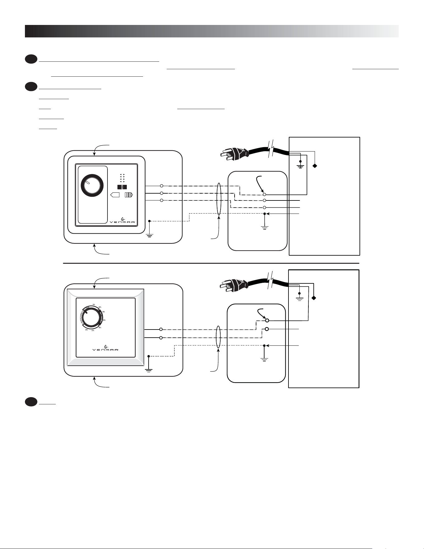
Electrical Installation.
Make hole in the wall at the chosen location for the control.
Run the AWG 14/2 and, if need be, the AWG 14/3 wire in the walls.
Connect the wires according to the drawings below.
Screw the control onto the wall.
7
8
VE0192A
WHT
BLK
GRN
Wire nut
NEMA
5-15P
PRO 200
Ground terminal
screw
Electrical compartment
RED
GREY
WHITE BLACK
WHITE
BLACK BLACK
WHITE
RED
RED
GREY
RED
14-3 AWG
Conductor
(Field wiring)
Junction box
Control
BLACK
WHITE
RED
20
30
40
50
60
70
80
% RELATIVE HUMIDITY
% HUMIDITÉ RELATIVE
0FF
25
-30˚C
-20˚C
-5˚C
5˚C+
55% 10°
45% 0°
35% -10°
30% -20°
%HUM. RELATIVE HUM EXT. TEMPS.°C EXT.
GROUND
VE0193A
PRO 100
RED
RED
WHITE WHITE
BLACK
BLACK
ORANGE
14-2 AWG
Conductor
(Field wiring)
BLACK
Junction box
Control
Ground terminal
screw
Wire nut
Electrical compartment
NEMA
5-15P
WHITE
BLACK
Ground terminal
screw
GROUND
WHT
BLK
GRN
Verify the operation of your unit:
Connect the unit to a power source. By adjusting the control as described in Sections 2.2b and 2.2c, verify that the unit works
properly. If the unit does not work properly, refer to the rules to follow on the warranty document of the unit.
9
Loading ...
Loading ...
Loading ...