Loading ...
Loading ...
Loading ...
18 Section 4— Product care
Parking Brake Adjustment
WARNING! Never attempt to adjust
the brakes while the engine is running.
Always disengage PTO, move shift
lever into neutral position, stop
engine and remove key to prevent
unintended starting.
If the tractor does not come to a complete stop
when the brake pedal is completely depressed,
or if the tractor’s rear wheels can roll with the
parking brake applied, the brake is in need of
adjustment. See an authorized service dealer to
have your brakes properly adjusted.
Cutting Deck Removal
NOTE: Models equipped with a 38-inch deck
have one deck idler pulley. Models equipped
with a 42- and 46-inch deck have two deck idler
pulleys.
To remove the cutting deck, proceed as follows:
1. Place the PTO lever in the disengaged
(OFF) position and engage the parking
brake.
2. Lower the deck by moving the deck lift
lever into the bottom notch on the right
fender.
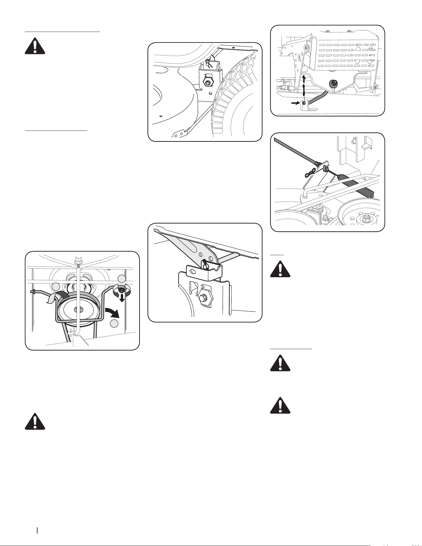
3. Removing the self-tapping screw (A) that
secures the belt-keeper rod from around
the tractor’s engine pulley, then remove
the belt keeper rod (B). See Figure 4-8.
A
B
C
Figure 4-8
NOTE: Make a note what hole the other
end of the belt-keeper rod is inserted in
for reinstallation purposes.
4. Remove the belt (C) from around the
tractor’s engine pulley. See Figure 4-8.
4.
WARNING! Avoid pinching injuries.
Never place your fingers on the idler
spring or between the belt and a
pulley while removing the belt.
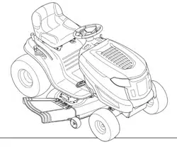
5. On 38” Decks: Looking at the cutting
deck from the left side of the tractor,
locate the bow tie pin that secures the
deck support rod on the rear left side
of the deck. See Figure 4-9. Remove the
bow tie cotter pin that secures the deck
support rod and carefully remove the deck
support from the deck lift arm. Repeat on
the tractors right side.
NOTE: The bow-tie hair-pin clips should be
re-installed from the top down.
Figure 4-9
6. On 42” & 46” Decks: Looking at the
cutting deck from the left side of the
tractor, remove the bow-tie cotter pin
securing the deck lift rod to the deck.
Slide the deck lift rod from the mounting
weldment on the deck as seen in Figure
4-10. Repeat on the tractor’s right side.
NOTE: The bow-tie hair-pin clips should be
re-installed from the top down.
Figure 4-10
7. On all decks: Move the deck lift lever into
the top notch on the right fender to raise
the deck lift arms up and out of the way.
8. On 38” Decks: Gently slide the cutting
deck toward the front of the tractor
carefully guiding the hooks on the deck
off of the deck stabilizer rod.
On 42” & 46” Decks: Remove the bow-tie
cotter pin securing the deck stabilizer rod
to the deck. Slide the deck lift rod from the
mounting weldment on the deck as seen
in Figure 4-11.
9. Carefully remove the PTO cable from the
rear of the cutting deck by removing the
hair pin clip which secures it. Remove the
spring from the deck idler bracket. See
Figure 4-12.
10. Gently slide the cutting deck (from the left
side) out from underneath the tractor.
Figure 4-11
Figure 4-12
Tires
WARNING! Never exceed the
maximum inflation pressure shown on
the sidewall of the tire.
The recommended operating tire pressure is:
• Approximately 10 psi for the rear tires
• Approximately 14 psi for the front tires
IMPORTANT: Refer to the tire sidewall for exact
tire manufacturer’s recommended or maximum
psi. Do not overinflate. Uneven tire pressure
could cause the cutting deck to mow unevenly.
Cutting Blades
WARNING! Shut the engine OFF and
remove the key before removing the
cutting blade(s) for sharpening or
replacement. Protect your hands by
using heavy gloves when grasping the
blade.
WARNING! Periodically inspect the
blade spindles for cracks or damage,
especially if you strike a foreign object.
Replace immediately if damaged.
The blades may be removed as follows:
1. Remove the deck from beneath the tractor,
(refer to Cutting Deck Removal on page
18) then gently flip the deck over to
expose its underside.
2. Place a block of wood between the center
deck housing baffle and the cutting blade to
act as a stabilizer. See Figure 4-13.
3. Remove the hex flange nut that secures the
blade to the spindle assembly. See Figure
4-13.
Loading ...
Loading ...
Loading ...