Loading ...
Loading ...
Loading ...
12 Section 3 — controlS & operation
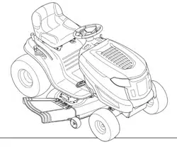
Shift Lever (If Equipped)
Foot Control CVT & CVT
The shift lever is located on the left side of the
fender and has three positions; FORWARD (F),
NEUTRAL (N) and REVERSE (R). The brake pedal
must be depressed and the lawn tractor must
not be in motion when moving the shift lever.
See Figure 3-22.
IMPORTANT: Never force the shift lever. Doing so
may result in serious damage to the lawn tractor’s
transmission.
Figure 3-2
Drive Pedal (If Equipped)
Foot Control CVT
The drive pedal is located on the
right side of the lawn tractor, along
the running board. Depress the
drive pedal forward and the lawn
tractor will move in the direction
that the shift lever is engaged in.
To cause the lawn tractor to travel
forward, while at a complete stop,
move the shift lever into the FORWARD (F)
position. Gradually step on the drive pedal and
the lawn tractor will begin to move forward. To
move in REVERSE (R), follow the same procedure
only move the shift lever into the REVERSE (R)
position.
The ground speed is controlled with the drive
pedal. The further forward that the pedal is
pivoted, the faster the lawn tractor will travel.
The pedal will return to its original position
when it’s not depressed. Refer to Driving the Lawn
Tractor on page 13 for detailed instructions
regarding the drive pedal.
IMPORTANT: Always set the parking brake when
leaving the lawn tractor unattended.
Headlights
The headlights are located on the front of the
lawn tractor.
• On some models, the lamps are ON when
the lawn tractor’s engine is running.
• On some models, the lamps are ON
whenever the ignition key is moved out of
the STOP position.
• On all models, the lamps turn OFF when
the ignition key is moved to the STOP
position.
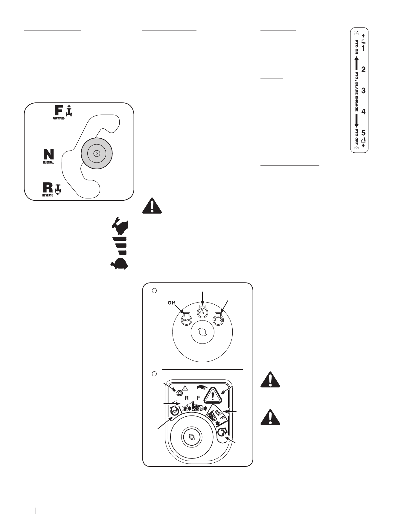
Ignition Switch Module
The lawn tractor will have one of the following
ignition switches. Refer to Figure 3-33 to identify
which switch your machine utilizes and follow
the applicable instructions for proper operation.
3-Position Ignition Switch (If Equipped)
The ignition switch is used to start the engine.
Insert key into the ignition switch and turn
clockwise to the START position. Release the
key into the ON position once engine has fired.
See Figure 3-33A. The engine will run with the
headlights ON.
To stop the engine, turn the key counter-
clockwise to the OFF position. See Figure
3-3A.
Ignition Switch Module (If Equipped)
To start the engine, insert the key into the
ignition switch and turn clockwise to the START
position. Release the key into the NORMAL
MOWING MODE position once the engine has
fired. The headlights will be activated in the
NORMAL (and REVERSE CAUTION MODES).
To stop the engine, turn the key counter-
clockwise to the OFF or STOP position. See
Figure 3-3B.
WARNING! Never leave a running
machine unattended. Always disengage
PTO, move shift lever into neutral
position, set parking brake, stop engine
and remove key to prevent unintended
starting.
IMPORTANT: Prior to operating the lawn tractor,
refer to both Safety Interlock Switches and Starting
The Engine in the Operation section of this manual
for detailed instructions regarding the Ignition
Switch Module and operating the lawn tractor in
REVERSE CAUTION MODE.
On/Lights
Start
A
B
Start
position
Indicator
Light
Reverse
Push
Button
Normal
Driving
Mode
Stop
position
Reverse
Caution
Mode
Position
Figure 3-3
Deck Lift Lever
The deck lift lever is located on the
lawn tractor’s right fender. It is used to
change the height of the cutting deck.
To use, move the lever to the left, then
place in the position best suited for
your application.
PTO Lever
The PTO Lever is located on the lawn
tractor’s right fender. It is used to
engage power to the cutting deck
or other optional attachments. To
operate, move the lever all the way
forward. Moving the lever all the way
rearward into the PTO OFF position
disengages power to the cutting deck
or attachment.
NOTE: The PTO lever must be in the
disengaged (PTO OFF) position when
starting the engine.
Safety Interlock Switches
This lawn tractor is equipped with a safety
interlock system for the protection of the
operator. If the interlock system malfunctions,
do not operate the lawn tractor. Contact an
authorized service dealer.
• The safety interlock system prevents the
engine from cranking or starting unless
the parking brake is engaged, and the
PTO lever is in the disengaged (PTO OFF)
position.
• The engine will automatically shut OFF
if the operator leaves the seat before
engaging the parking brake.
• The engine will automatically shut OFF if
the operator leaves the lawn tractor’s seat
with the PTO lever in the engaged (PTO
ON) position, regardless of whether the
parking brake is engaged.
3-Position Ignition Switch (If Equipped)
• The engine will automatically shut OFF if
the PTO lever is moved into the engaged
(PTO ON) position with the speed control
lever in REVERSE (R) position.
Ignition Switch Module (If Equipped)
• With the ignition key in the NORMAL
DRIVING MODE position, the engine
will automatically shut OFF if the PTO
lever is moved into the engaged (PTO
ON) position with the speed control in
REVERSE (R) position.
WARNING! Do not operate the lawn
tractor if the interlock system is
malfunctioning. This system was
designed for your safety and protection.
Reverse Caution Mode (If Equipped)
WARNING! Use extreme caution while
operating the lawn tractor in the
REVERSE CAUTION MODE. Always look
down and behind before and during
lawn tractor backing. Do not operate
the lawn tractor when children or others
are around. Stop the lawn tractor
immediately if someone enters the area.
The REVERSE CAUTION MODE position of the
ignition switch module allows the lawn tractor
to be operated in reverse with the blades (PTO)
engaged.
IMPORTANT: Mowing in the reverse direction is not
recommended.
Loading ...
Loading ...
Loading ...