Loading ...
Loading ...
Loading ...
6
INSTALLATION
Oven Location and Leveling
The well planned and proper placement of your oven will
result in long term operator convenience and satisfactory
performance.
Certain minimum clearances must be maintained be-
tween the oven and any combustible or non-combustible
construction.
MINIMUM REQUIRED CLEARANCES
Size Left Right
(control side)
Back
Low Temperature Environment
6 & 10 2”
(50mm)
2”
(50mm)
2”
(50mm)
61, 62, 101,
102 & 202
2”
(50mm)
2.8”
(70mm)
2”
(50mm)
High Temperature Environment*
6 & 10 2”
(50mm)
16”
(400mm)
2”
(50mm)
61, 62, 101,
102 & 202
2”
(50mm)
16”
(400mm)
2”
(50mm)
* Includes heat sources (fryers, hot plates, etc) placed on
the control side of the combi
NOTE: For servicing, Blodgett recommends maintaining
at least 16” (400 mm) between the control side
and walls or non moveable equipment.
• Do not place strong sources of heat such as open
ame ranges, griddles, or charbroilers near the oven.
If such an instance exists, it is highly recommended
to purchase a heat shield, available from Blodgett.
• Note that if temperatures are too high, a safety shut-
down may occur.
• Failure to comply may invalidate the oven warranty.
In addition, the following clearances are recommended
for servicing.
• Oven body sides - 12” (30cm)
• Oven body back - 12” (30cm)
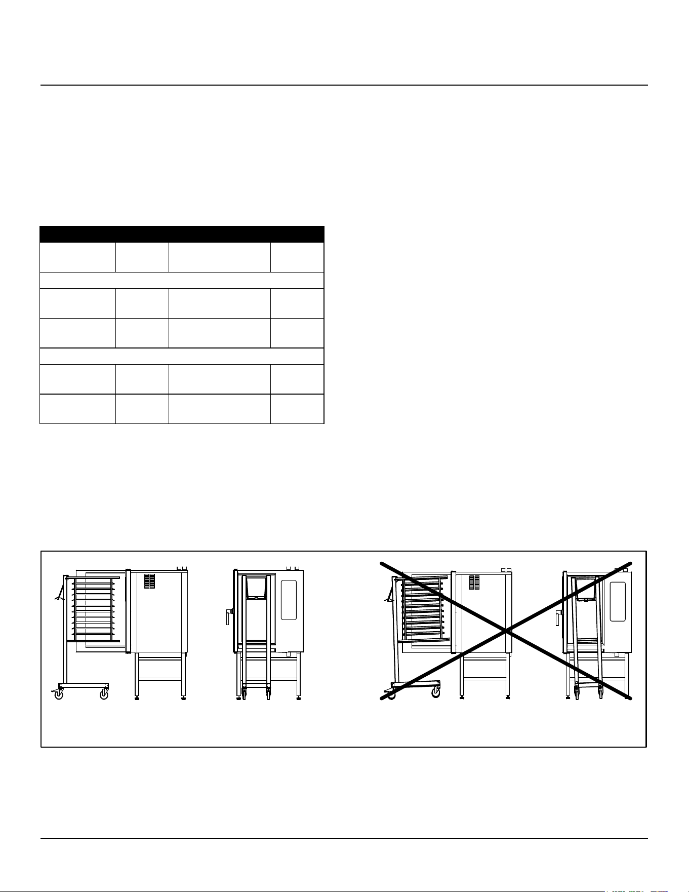
To ensure that the oven functions correctly when installed,
it should be placed upright and level (horizontally). This is
measured at the front and side edge of the roof. The oven
can be levelled using the adjusting screws on the stand or
on the legs of table models. The height of the oven should
also be adjusted to t the trolley for rack.
Correct Installation Incorrect Installation
Figure 1
Loading ...
Loading ...
Loading ...