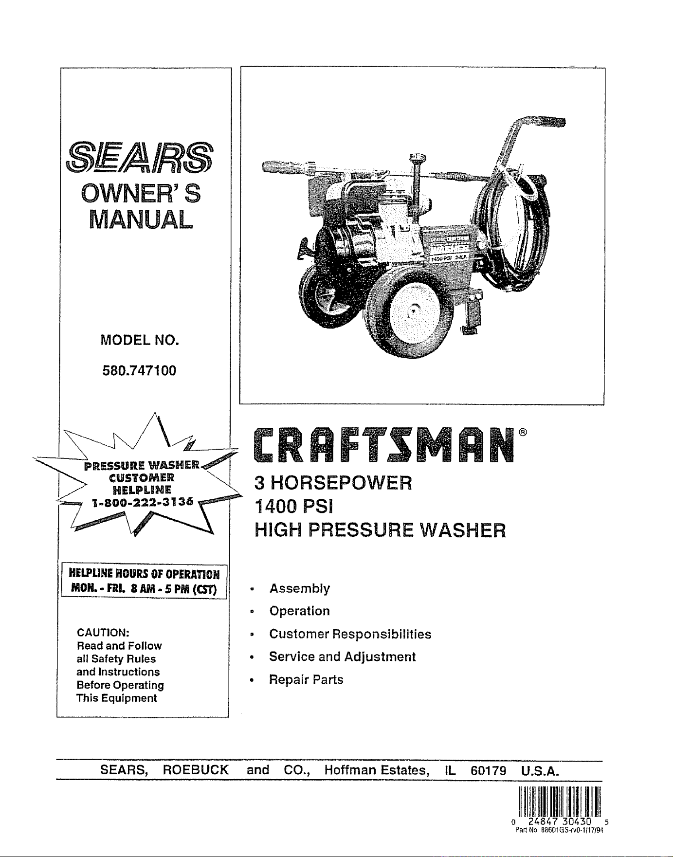
OWNER'S
MANUAL
MODEL NO.
580.747100
®
HELPUHEHOURSOFOPERATIOH
_oH.. F_L8 AM- SPM(CS_
CAUTION:
Read and Follow
all Safety Rules
and instructions
Before Operating
This Equipment
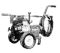
3 HORSEPOWER
1400 PSi
HIGH PRESSURE WASHER
. Assembly
• Operation
• Customer Responsibilities
° Service and Adjustment
• Repair Parts
SEARS, and CO., Hoffman Estates, IL 60179 U.S.A.
!lllll
o 24847 30430 5
Par_No 88601GS_rv0.1/17/94
SAFETY RULES
CAUTION: ALWAYS DISCONNECT SPARK PLUG WIRE AND PLACE WIRE WHERE IT CANNOT
CONTACT SPARK PLUG, TO PREVENT ACCIDENTAL STARTING WHEN SETTING UP, TRANS-
PORTING, ADJUSTING OR MAKING REPAIRS TO YOUR HIGH PRESSURE WASHER.
TRAINING:
= Engine exhaust gases contain DEADLY carbon mon-
oxide gas., This dangerous gas, if breathed in suffi-
cient concentrations, can cause unconsciousness or
. even death., Operate this equipment only in the open
air where adequate ventilation is avaitable_
• Gasoline is higl_ly FLAMMABLE and its vapors are
EXPLOSIVE. Do not permit smoking, open flames,
sparks or heat in the vicinity while handling gasoline.
Avoid spilling gasoline on a hot engine° Allow unit to
cool for 2 minutes before refueling. Comply with all
taws regulating storage and handling of gasoline.
" Locate this pressure washer in areas away from corn-
bustible materials, combustible fumes or dust..
o The high pressure equipment is designed to be used
with Sears authorized parts only. If you use this
equipment with parts that do not comply with minimum
specifications, the user assumes all risks and liabili-
ties.,
• Some chemicals or detergents may be harmful if
inhaled or ingested, causing severe nausea, fainting
or poisoning. The harmful elements may cause prop-
erty damage or severe injury..
o Do not allow CHILDREN to operate the Pressure
Washer at any time.
PREPARATION:
o Operate engine only at governed speed.. Running the
engine at excessive speeds increases the hazard of
personal injury. Do not tamper with parts which may
increase or decrease the governed speed.,
o Do not wear loose clothing, jewelry or anything that
may be caught in the starter or other rotating parts,.
= Before starting the Pressure Washer in cold weather,
check all parts of the equipment and be sure ice has
not formed there,.
" Units with broken or missing parts, or without protec-
tive housing or covers should NEVER be operated.,
o The muffler and air cleaner must be installed and in
good condition before operating the Pressure Washer.
These components act as spark arrestors if the engine
backfires_
• Check the fuet system for leaks or signs of deteriora-
tion such as chafed or spongy hose, loose or missing
clamps or damaged tank or cap. Correct all defects
before operating the Pressure Washer.
OPERATION;
" Do not spray flammable liquids,
o Never aim the gun at people, animals or plants..
= Never allow any part of the body to come in contact
with the fluid stream. DO NOT come in contact with a
fluid stream created by a leak in the high pressure
hose.
• High pressure stream of fluid that this equipment can
produce can pierce skin and its underlying tissues,
leading to serious injury and possible amputationv
• High pressure spray can cause paint chips or'other
particles to become airborne and fly at high speeds.
• Always wear eye protection when you use this equip-
ment or when you are in the vicinity where the equip-
ment is in use.
• Operate the pressure at no more than the PS1 fluid
pressure rated for'your pressure washer,.
'_ Never move the machine by pulling on the high pres-
sure hose,. Use the handle provided on the top of the
unit,,
o Always be certain the spray gun, nozzles and acces-
sories are correctly attached.
• Never use a spray gun which does not have a trigger
lock or trigger' guard in place and in working order.
• Use a respirator or mask whenever there is a chance
that vapors may be inhaled,. Read all instructions with
the mask so you are certain the mask will provide the
necessary protection against inhaling harmful vapors.
• High pressure spray may damage fragile items includ-
ing glass, Do not point spray gun at glass when in the
jet spray mode,
• Keep the hose connected to machine or the spray gun
while the system is pressurized.. Disconnecting the
hose while the unit is pressurized is dangerous,
• Hold the spray gun firmly in your' hand before you start
the unit., Failure to do so could result in an injury from
a whipping spray gun_ Do not leave the spray gun
unattended while the machine is running.
• The cleaning area should have adequate slopes and
drainage to reduce the possibility of a fall due to
slippery surfaces_
• Keep water spray away from electric wiring or fatal
electric shock may resulL
o Do not adjust unloader valve to a pressure in excess
of machine rating.
o Do not secure trigger gun in the pull-back (open)
position.
• Do not by-pass any safety device on this machine,
• Do not leave trigger closed for more than 5 minutes
with engine running. This could damage the pump.
• The muffler and engine heat up during operation and
remain hot immediately after shutting it down. Avoid
contact with a hot muffler or engine or you could be
severely burned.
MAINTENANCE AND STORAGE;
• Operate and store this unit on a stable surface.
• High pressure hose can develop leaks from wear,
kinking, abuse, etc. Water spraying from a leak is
capable of injecting material into skin, Inspect hose
each time before using iL Check all hoses for cuts,
leaks, abrasions or bulging of cover, or damage or
movement of couplings. If any of these conditions
exist, replace hose immediately_ Never repair high
pressure hose. Replace it with another hose that
meets minimum pressure rating of your' pressure
washer.
LOOK FOR THIS SYMBOL TO POINT OUT IMPORTANT
SAFETY PRECAUTIONS° IT MEANS "ATTENTION!!! BE-
COME ALERT!!! YOUR.SAFETY IS INVOLVED."
CONGRATULATtONS on your purchase of a Sears Crafts-
man high pressure washer° it has been designed, engi-
neered and manufactured to give you the best possible
dependability and performance.
Should you experience any problem you cannot easily
remedy, please contact your nearest Sears Service Cen-
ter/Department We have competent, well-trained techni-
cians and the proper tools to service or repair this unit.
Please read and retain this manual, The instructions will
enable you to assemble and maintain your high pressure
washer properly, Always observe the "SAFETY RULES."
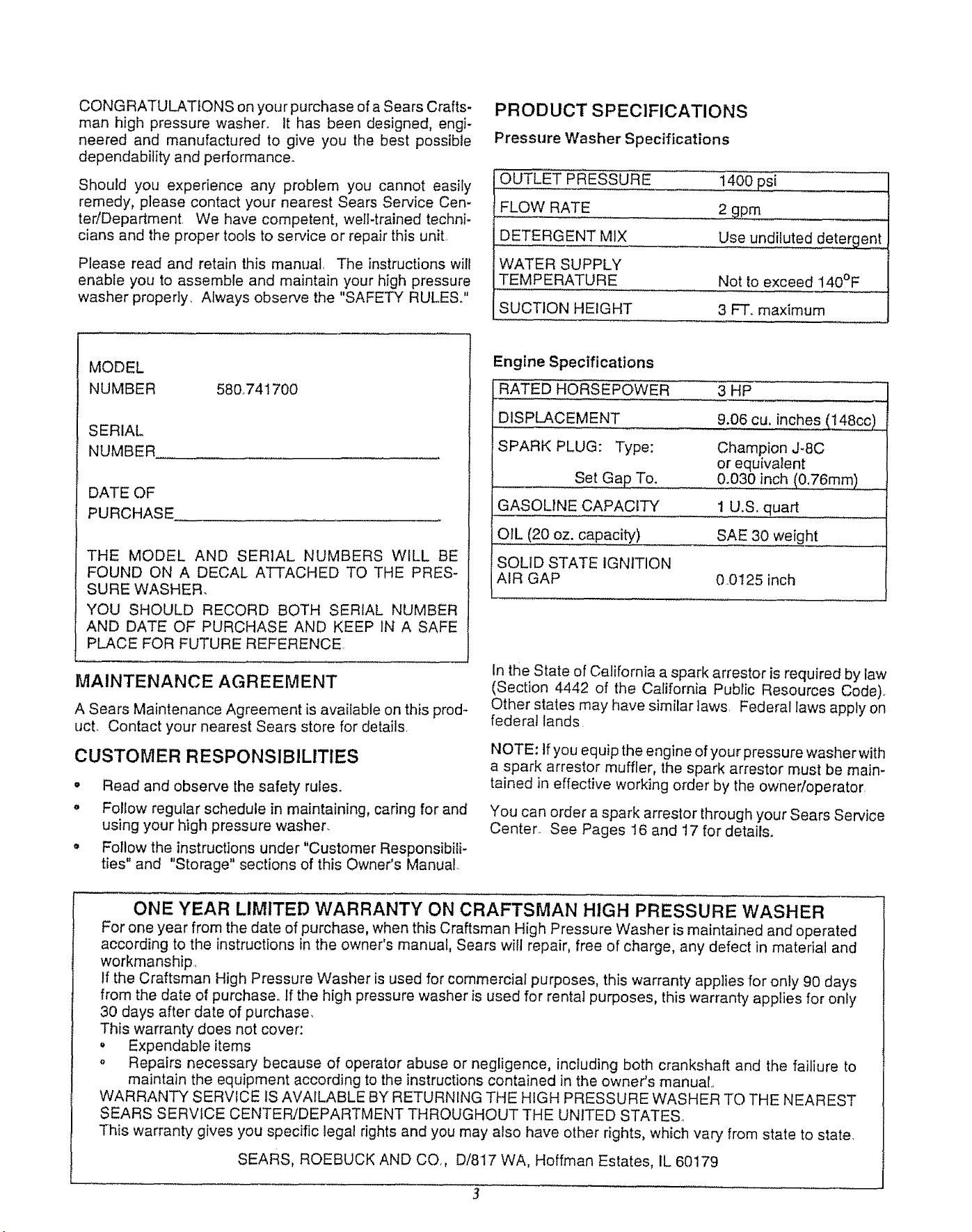
PRODUCT SPECIFICATIONS
Pressure Washer Specifications
OUTLET PRESSURE
FLOW RATE
DETERGENT MIX
WATER SUPPLY
TEMPERATURE
SUCTION HEIGHT
1400 psi
2 gpm
Use undiluted detergent
Not to exceed 140°F
3 FT'. maximum
3HP
9.06 CU.inches (_
MODEL
NUMBER 580_741700
SERIAL
NUMBER
DATE OF
PURCHASE
THE MODEL AND SERIAL NUMBERS WILL BE
FOUND ON A DECAL ATTACHED TO THE PRES-
SURE WASHER.
YOU SHOULD RECORD BOTH SERIAL NUMBER
AND DATE OF PURCHASE AND KEEP 1N A SAFE
PLACE FOR FUTURE REFERENCE.
MAINTENANCE AGREEMENT
A Sears Maintenance Agreement is available on this prod-
uct. Contact your nearest Sears store for details.
CUSTOMER RESPONSIBILITIES
" Read and observe the safety rules.
o Follow regular schedule in maintaining, caring for and
using your high pressure washer.
o Follow the instructions under "Customer Responsibili-
ties" and "Storage" sections of this Owner's Manual,.
Engine Specifications
RATED HORSEPOWER
DISPLACEMENT
SPARK PLUG: Type:
Set Gap To.
GASOLINE CAPACITY
OIL (20 oz. capacity)
SOLID STATE IGNITION
AIR GAP
Champion J-8C
or equivalent
0.030 inch (0,76m.m) ....
1 U.S. quart
SAE 30 weight
0.0125 inch
In the State of California a spark arrestor is required by law
(Section 4442 of the California Public Resources Code).
Other states may have similar taws. Federal laws apply on
federal lands
NOTE: If you equip the engine of your pressure washer with
a spark arrestor muffler, the spark arrestor must be main-
tained in effective working order by the owner/operator
You can order a spark arrestor through your Sears Service
Center. See Pages 16 and 17 for details.
ONE YEAR LIMITED WARRANTY ON CRAFTSMAN HIGH PRESSURE WASHER
For one year from the date of purchase, when this Craftsman High Pressure Washer is maintained and operated
according to the instructions in the owner's manual, Sears wilt repair, free of charge, any defect in material and
workmanship.
If the Craftsman High Pressure Washer is used for commercial purposes, this warranty applies for only 90 days
from the date of purchase,. If the high pressure washer is used for rental purposes, this warranty applies for only
30 days after date of purchase.
This warranty does not cover:
Expendable items
o Repairs necessary because of operator abuse or negligence, including both crankshaft and the failiure to
maintain the equipment according to the instructions contained in the owner's manual
WARRANTY SERVICE IS AVAILABLE BY RETURNING THE HIGH PRESSURE WASHER TO THE NEAREST
SEARS SERVICE CENTER/DEPARTMENT THROUGHOUT THE UNITED STATES
This warranty gives you specific legal rights and you may also have other rights, which vary from state to state,
SEARS, ROEBUCK AND CO,, D/817 WA, Hoffman Estates, IL 60179
TABLE OF CONTENTS
SAFETY RULES ................................................................2
PRODUCT SPECIFICATIONS ................................. 3
ACCESSORIES AND ATTACHEMENTS ............. 4
CONTENTS OF HARDWARE PACK ...................... 5
ASSEMBLY .............................................................................6
OPERATION ............................................................7-10
CUSTOMER RESPONSIBILITIES ................. 11-12
SERVICE AND ADJUSTMENTS .......................... 12
STORAGE ............................................................ 13
TROUBLESHOOTING ............................................. 14
REPLACEMENT PARTS ................................ 15-19
INDEX
-A-
Air Cleaner , .............. 7,12
Assembly
Removing from Carton ........... 6
Tools Required ..................... 6
Set Up ................................... 6
ma_
Before Starting ........... :.. 9
--C--
Carburetor _ ............... 12
Customer Responsibilities . 1,11
Changing Oil ...................... 11
Checking Oil Level .................... 1 t
General Recommendations ....... 11
Pump ................................. 12
Replace Spark Plug ................ 12
Service Air Cleaner .................. 12
-E-
Engine Speed ............... 12
-G-
Gun and Wand Assembly .. 6, 7
-H-
Hardware Pack ............. 5
High Pressure Hose ......... 7
-M-
Maintenance
Engine .......................... 12
Pump ............................ 11, 13
-O-
Oil, Engine .................. 9
Operation
Detergent Application .............. 8
Stopping ............................. 8
To Start Engine .................. 10
To Turn On Washer ............. 9
To Use .......................... 8
-p-
Parts Shipped Loose ....... 6
Preparing Washer ........... 6
Pressure Regulator ........... 7
-R-
Repair Parts ............ 15-19
-S-
Safety Latch ............... 9
Service and Adjustments °.. 12
Storage ................... 13
Engine ....................... 13
PressureWasher Pump ....... 13
-T-
Troubleshooting .......... 14
-W-
Warranty .................. 3
ACCESSORIES AND ATTACHMENTS
These accessories and attachments were available when the high pressure washer was purchased° They are also
available at most Sears retail outlets and service centers. Most Sears stores can order these items for you when you
provide the model number of your high pressure washer.
HOUSE WASH DECK WASH VEHICLE WASH DEGREASER ROTATING BRUSH
74273 74274 74275 74276 74189
4
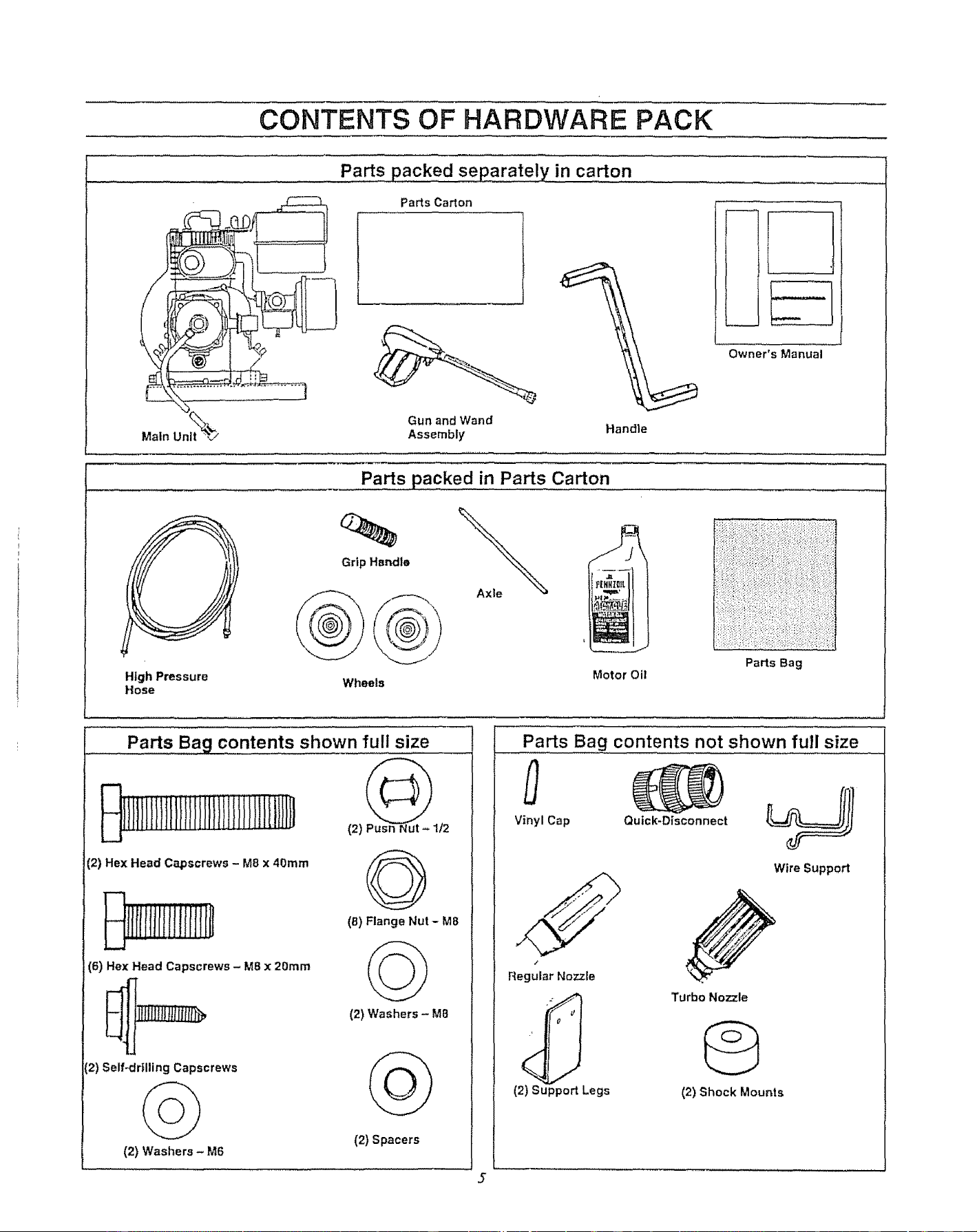
CONTENTS OF HARDWARE PACK
Parts packed separately in carton
Main
Parts Ca_on
Gun and Wand
Assembly Handle
Owner's Manual
High Pressure
Hose
Parts packed in Parts €,,a,_o,n........
Grip Hsndle
Wheels
Motor Oi!
Parts Bag
Parts Bag contents shown full size
(2) Hex Head Capscrews - M8 x 40ram
irliilriitffrJir
O
(8) Flange Nut - M8
(6) Hex Head Capscrews - M8 x 20mm
2) Self-drilling Capscrews
(2) Washers _ M6
(2) Washers - M8
(2) Spacers
5
Parts Bag contents not shown full size
Vinyl Cap Quick*Disconnect __.JJ II
Wire Support
/
Regular Nozzle
(2) Support Legs
Turbo Nozzle
G
(2) Shock Mounts
Read these instructions and Operator's Manual in its en-
tirety before you attempt to assemble or operate your new
high pressure washer. Your high pressure washer has, for
the most part, been assembled at the factory, except those
parts left unassembted. Before you can operate your' new
high pressure washer, you must assemble the wheel kit and
properly connect the high pressure hose.
IF YOU HAVE ANY PROBLEMS WITH THE ASSEM-
BLY OF YOUR PRESSURE WASHER, PLEASE
CALL THE PRESSURE WASHER CUSTOMER
HELPLINE AT 1-800-222-3136.
TOOLS REQUIRED FOR ASSEMBLY
• Mallet
• Socket wrench with 1/2-inch or 13ram Sockets
• Crescent Wrenches or Combination Wrenches
• 8ram nut driver
TO REMOVE
CARTON
Q
PRESSURE WASHER FROM
Remove guide handle (wrapped in plastic)o
Remove accessories box from carton_
Remove gun/wand assembly from cardboard holder.
Remove all other packing material from box before
removing your high pressure washer.
HOWTO SET UP YOUR PRESSURE WASHER
TO INSTALL THE WHEEL KIT
Installing wheel kit, requires the tools listed above, the
guide handle and items included in the parts carton. You
can also refer to the Parts Illustration on Page 15.
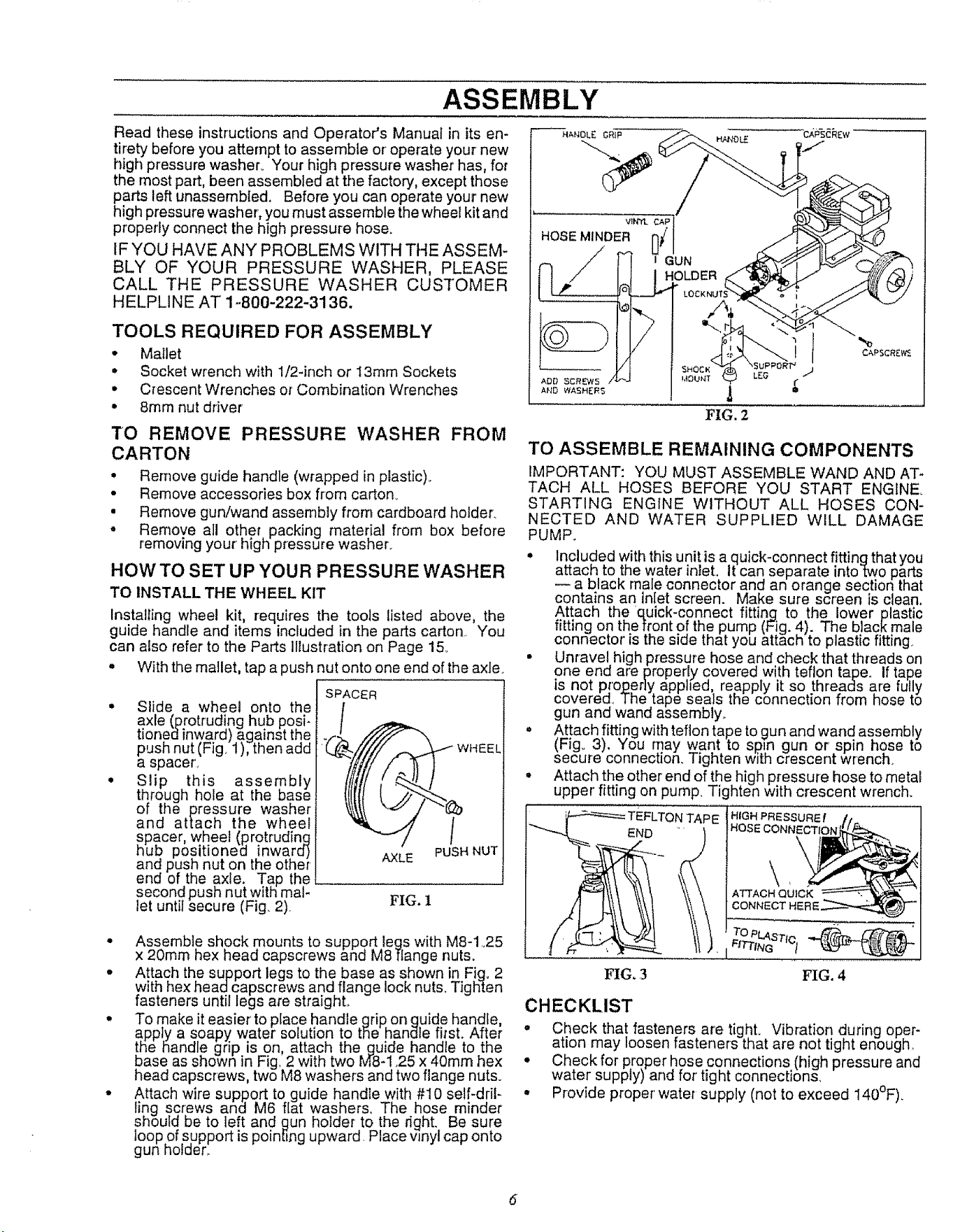
• With the mallet, tap a push nut onto one end of the axle.
Slide a wheel onto the
axle (protruding hub posi-
tionedinward) against the
push nut (Fig. 1), then add
a spacer',
Slip this assembly
through hote at the base
of the pressure washer
and attach the wheel
_pacer, wheel (protruding
ub positioned inwara)
and push nut on the other
end of the axle. Tap the
second push nut with mal-
let until secure (Fig. 2)
SPACER
AXLE PUSH NUT
FIG. 1
• Assemble shock mounts to support legs with M8-1 25
x 20mm hex head capscrews and M8 flange nuts.
• Attach the support legs to the base as shown in Fig, 2
with hex head capscrews and flange lock nuts. Tighten
fasteners until legs are straight.
• To make it easier' to place handle grip. on guide handle,
appJy a soapy water solution to the handle first. Af!er
!he handle grip is on attach the guide handle to the
Dose as shown in Fig, 2 with two M8-1,25 x 40mm hex
head capscrews, two M8 washers and two flange nuts.
• Attach wire support to guide handle with #I0 self-dril-
ling screws and M6 flat washers. The hose minder
should be to left and gun holder to the right. Be sure
loop of support is pointing upward Place wnyt cap onto
gun holder,.
TO ASSEMBLE REMAINING COMPONENTS
IMPORTANT: YOU MUST ASSEMBLE WAND AND AT-
TACH ALL HOSES BEFORE YOU START ENGINE.
STARTING ENGINE WITHOUT ALL HOSES CON-
NECTED AND WATER SUPPLIED WILL DAMAGE
PUMP.
• Included withthis unit is a quick-connect fitting that you
attach to the water inlet, It can separate into two parts
a black male connector and an orange section that
contains an inlet screen. Make sure screen is clean.
Attach the quick-connect fitting to the lower plastic
fitting on the front of the pump (Fig. 4). The black male
connector is the side that you attach to plastic fitting
• Unravel high pressure hose and check that threads on
one end are properly covered with teflon tape. If tape
is not proper],/apphed, reapply it so threads are fully
covered, The tape seals the connection from hose to
gun and wand assembly_
• Attach fitting with teflon tape togun and wand assembly
(Fig. 3). You may want to sp)n gun or spin hose to
secure connection. Tighten with crescent wrench.
• Attach the other end of the high pressure hose to metal
upper' fitting on pump. Tighten with crescent wrench.
END
FIG. ,3
rAPE
TO PLASTrc,
FITTING t
FIG. 4
CHECKLIST
o Check that fasteners are tight. Vibration during oper-
ation may loosen fasteners that are not tight enough_
• Checkfor proper hose connections (high pressure and
water supply) and for tight connections,
• Provide proper' water supply (not to exceed 140°F).
6
OPERATION
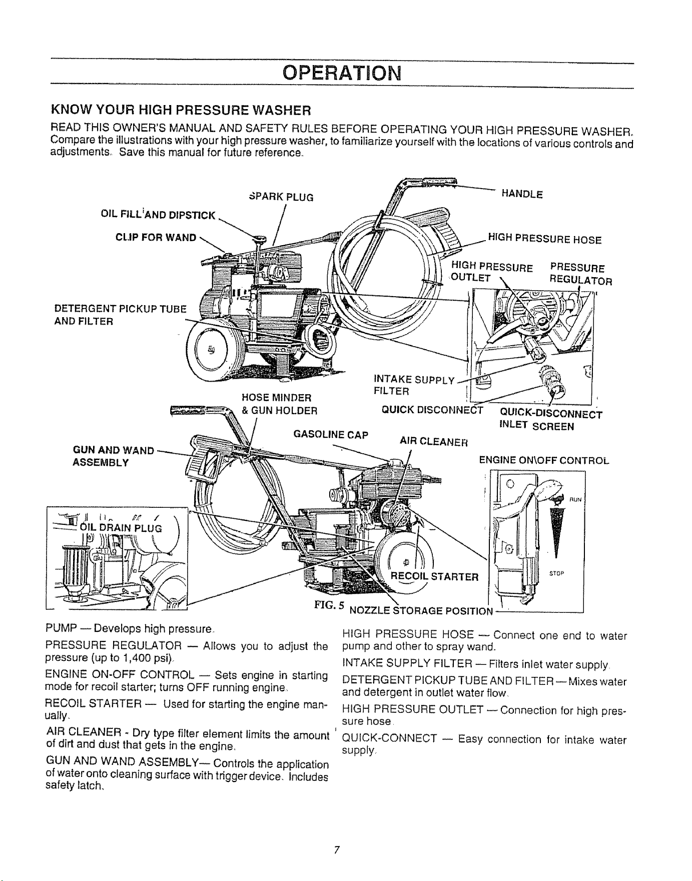
KNOW YOUR HIGH PRESSURE WASHER
READ THIS OWNER'S MANUAL AND SAFETY RULES BEFORE OPERATING YOUR HIGH PRESSURE WASHER.
Compare the illustrations with your high pressure washer, to familiarize yourself with the locations of various controls and
adjustments° Save this manual for future reference.,
OIL FILL_AND DIPSTICK
CLIP FOR
SPARK PLUG
HANDLE
HIGH PRESSURE HOSE
HIGH PRESSURE PRESSURE
REGULATOR
DETERGENT PICKUP TUBE
AND FILTER
GUN AIi
ASSEMBLY
HOSE M1NDER
& GUN HOLDER
GASOLINE CAP
INTAKE SUPP
FILTER I
QUICK DISCONNECT
AIR CLEANER
QUICK-DISCONNECT
INLET SCREEN
ENGINE ON\OFF CONTROL
DRAIN PLUG
RECOIL STARTER
_UN
F,[G+ 5 NOZZLE STORAGE POSITION
PUMP -- Develops high pressure
PRESSURE REGULATOR -- Allows you to adjust the
pressure (up to 1,400 psi).
ENGINE ON-OFF CONTROL -- Sets engine in starting
mode for recoil starter; turns OFF running engine,,
RECOIL STARTER -- Used for starting the engine man-
ually.
AIR CLEANER. Dry type filter element limitsthe amount
of dirt and dust that gets in the engine.
GUN AND WAND ASSEMBLY-- Controls the application
of water onto cleaning surface with trigger device. Includes
safety latch.
HIGH PRESSURE HOSE --Connect one end to water
pump and other to spray wand.
INTAKE SUPPLY FILTER i Filters inlet water supply,
DETERGENT PICKUP TUBE AND FILTER --Mixes water
and detergent in outlet water flow,
HIGH PRESSURE OUTLET -- Connection for high pres-
sure hose
QUICK-CONNECT -- Easy connection for intake water
supply,
OPERATION
HOW TO USE YOUR WASHER
tF YOU HAVE ANY PROBLEMS OPERATING YOUR
PRESSURE WASHER, PLEASE CALL THE PRESSURE
WASHER CUSTOMER HELPLINE AT 1-800-222-3136.
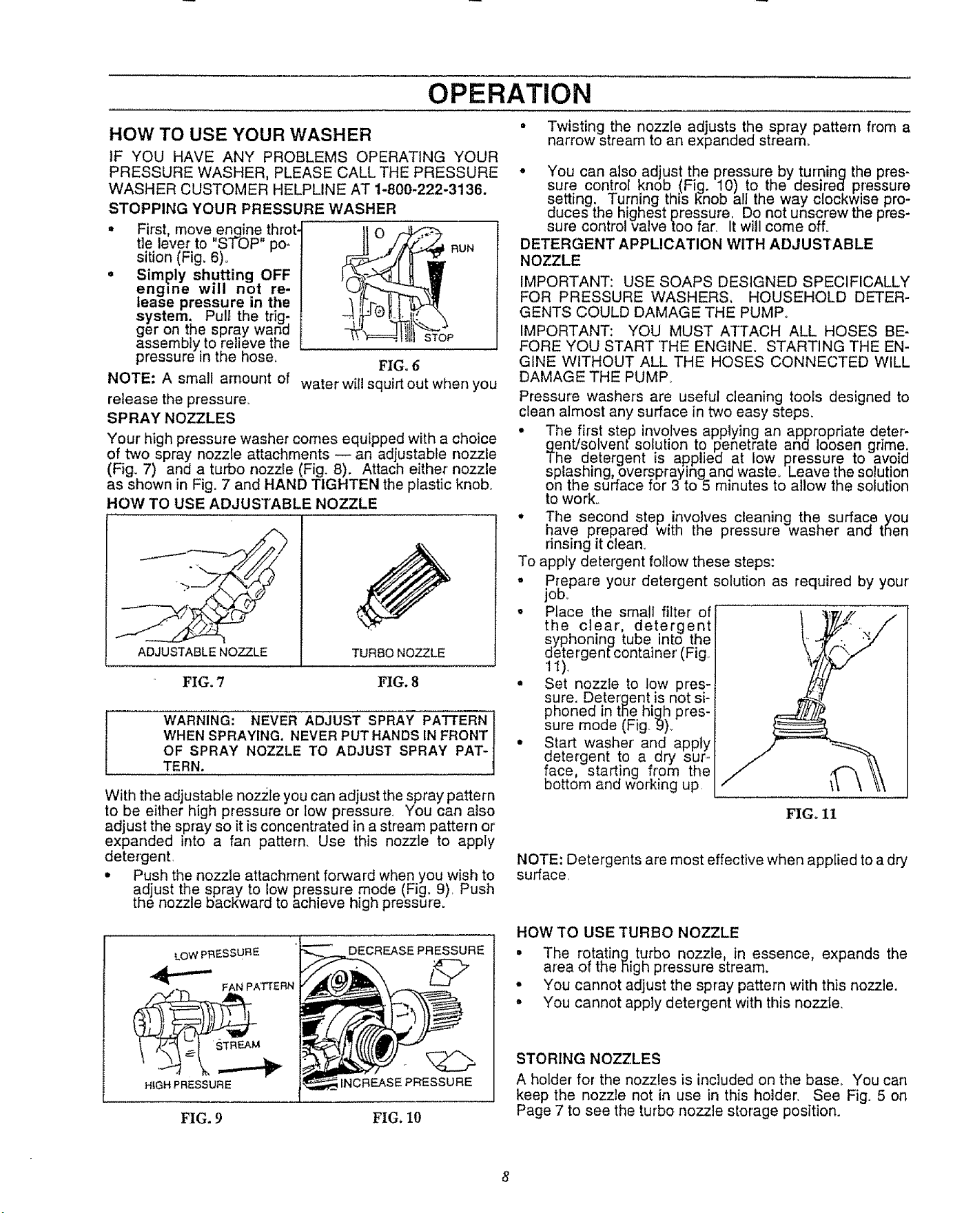
STOPPING YOUR PRESSURE WASHER
• First, move engine throt-
tle lever to "STOP" po_ nun
sition (Fig. 6)°
° Simply shutting OFF
engine will not re-
lease pressure in the
system. Pull the trig;
ger on the spray wan(]
assembly to relieve the
pressure in the hose.
NOTE: A small amount of
release the pressure.
SP RAY NOZZLES
STOP
FIG. 6
water will squirt out when you
Your' high pressure washer comes equipped with a choice
of two spray nozzle attachments -- an adjustable nozzle
(Fig. 7) and a turbo nozzle (Fig. 8). Attach either nozzle
as shown in Fig. 7 and HAND TIGHTEN the plastic knob_
HOW TO USE ADJUSTABLE NOZZLE
ADJUSTABLE NOZZLE TURBO NOZZLE
FIG. 7 FIG. 8
WARNING: NEVER ADJUST SPRAY PATTERN
WHEN SPRAYING. NEVER PUT HANDS IN FRONT
OF SPRAY NOZZLE TO ADJUST SPRAY PAT-
TERN.
With the adjustable nozile you can adjust the spray pattern
to be either high pressure or tow pressure. You can also
adjust the spray so it is concentrated in a stream pattern or
expanded into a fan pattern. Use this nozzle to apply
detergent
* Push the nozzle attachment forward when you wish to
adjust the spray to low pressure mode (Fig. 9) Push
the nozzle bacl_ward to achieve high pressure.
LOW PRESSURE
FAN pATTERN
DECREASE PRESSURE
HiGH PRESSURE INCREASE PR'ESSURE
£IG.9 FIG. 10
• Twisting the nozzle adjusts the .spray pattern from a
narrow stream to an expanded stream.
• You can also adjust the pressure by turninq the pres-
sure control knob (Fig. 10) to the desired pressure
setting. /urning this _nob all the way clockwise pro-
duces the highest pressure, Do not unscrew the pres-
sure comrot vazve too rat, It will come off.
DETERGENT APPUCATION WiTH ADJUSTABLE
NOZZLE
IMPORTANT: USE SOAPS DESIGNED SPECIFICALLY
FOR PRESSURE WASHERS, HOUSEHOLD DETER-
GENTS COULD DAMAGE THE PUMP.
IMPORTANT: YOU MUST ATTACH ALL HOSES BE-
FORE YOU START THE ENGINE. STARTING THE EN-
GINE WITHOUT ALL THE HOSES CONNECTED WILL
DAMAGE THE PUMR
Pressure washers are useful cleaning tools designed to
clean almost any surface in two easy steps.
• The !irs.t step involves applying an appropriate deter-
gem/solyent solution to penetrate anu loosen grime:
The oetergent is applied at low pressure to avoia
splashing, overspraying and waste° Leave the solution
on the surface for 3 to 5 minutes to allow the solution
to work°
• The second step involves cleaning the surface you
have prepared with the pressure washer and then
rinsing it clean.
To apply detergent follow these steps:
° P!epare your detergent solution as required by your'
IOD,,
° Place the small filter of
the clear', detergent
syphoning tube into the
detergenfcontainer (Fig
11),
• Set nozzle to low pres-:i
sure. Deter.qent is not si-i
phoned in tile high pres-
sure mode (Fig. 9)_
• Start washer' and apply
detergent to a dry sur-
face, starting from the
bottom and working up \\ \
FIGo11
NOTE:Detergentsare mosteffectivewhenappliedtoad_
surface
HOW TO USE TURBO NOZZLE
• The rotatinq turbo nozzle, in essence, expands the
area of the }Sighpressure stream.
° You cannot adjust the spray pattern with this nozzle.
• You cannot apply detergent with this nozzle.
STORING NOZZLES
A holder for the nozzles is included on the base. You can
keep the nozzle not in use in this holder. See Fig. 5 on
Page 7 to see the turbo nozzle storage position.
8
OPERATION
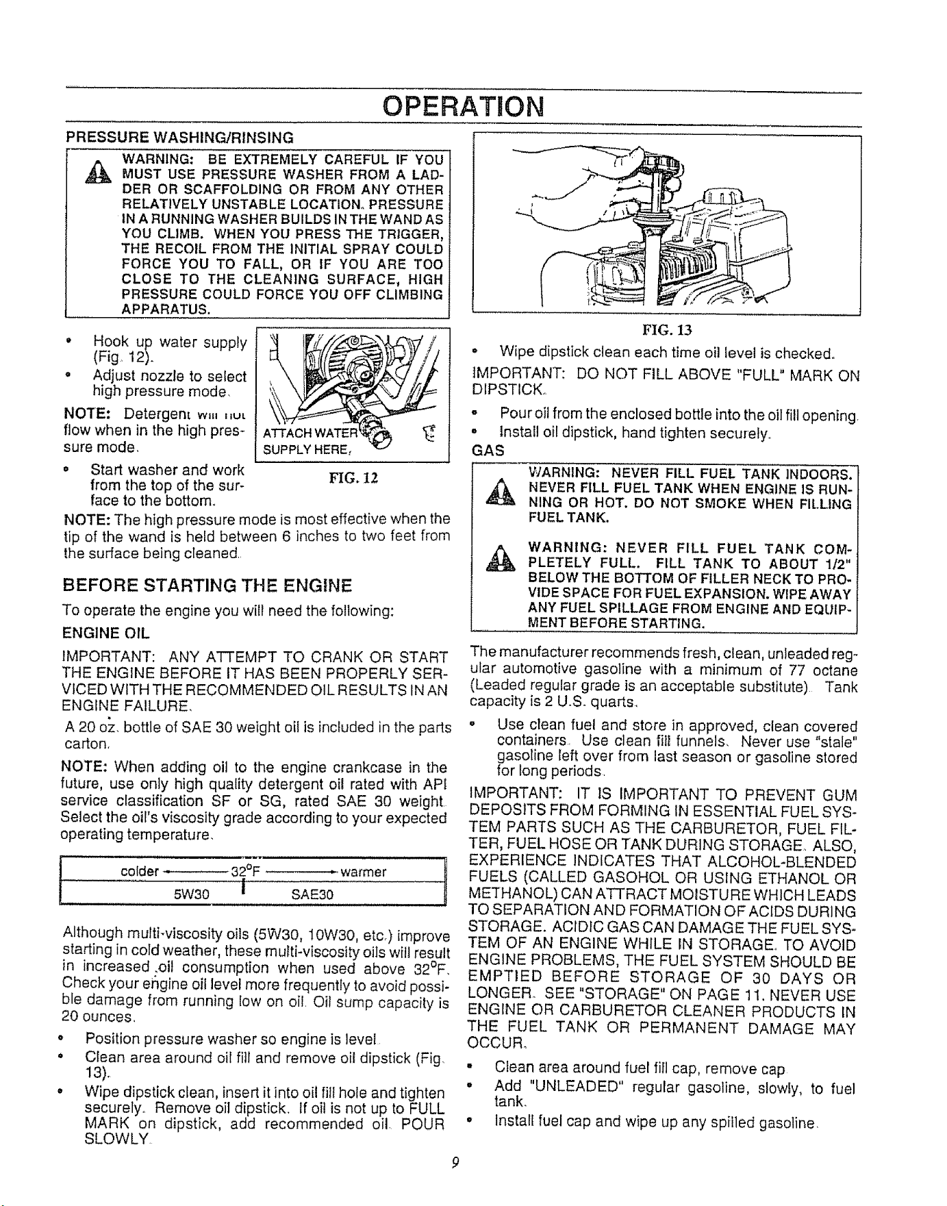
PRESSURE WASHING/RINSING
WARNING: BE EXTREMELY CAREFUL IF YOU
MUST USE PRESSURE WASHER FROM A LAD-
DER OR SCAFFOLDING OR FROM ANY OTHER
RELATIVELY UNSTABLE LOCATION° PRESSURE
IN A RUNNING WASHER BUILDS IN THE WAND AS
YOU CLIMB. WHEN YOU PRESS THE TRIGGER,
THE RECOIL FROM THE INITIAL SPRAY COULD
FORCE YOU TO FALL, OR IF YOU ARE TOO
CLOSE TO THE CLEANING SURFACE, HIGH
PRESSURE COULD FORCE YOU OFF CLIMBING
APPARATUS.
• Hook up water supply
(Fig 12).
, Adjust nozzle to select
high pressure mode.
NOTE: Detergent wu, ,_u_
flow when in the high pres-
sure mode.
• Start washer and work
from the top of the sur-
face to the bottom..
NOTE: The high pressure mode is most effective when the
tip of the wand is held between 6 inches to two feet from
the sudace being cleaned..
BEFORE STARTING THE ENGINE
To operate the engine you will need the following:
ENGINE OIL
IMPORTANT: ANY ATTEMPT TO CRANK OR START
THE ENGINE BEFORE IT HAS BEEN PROPERLY SER-
VICED WITH THE RECOMMENDED OIL RESULTS tNAN
ENGINE FAILURE,
A 20 oz. bottle of SAE 30 weight oil is included in the parts
carton.
NOTE: When adding oil to the engine crankcase in the
future, use only high quality detergent oil rated with APt
service classification SF or SG, rated SAE 30 weight.
Select the oil's viscosity grade according to your expected
operating temperature.
colder = 32°F - warmer
5W30 i SAE30
J
Although multi-viscosity oils (5W30, 10W30, etcr)improve
starting in cold weather, these multi-viscosity oils will result
in increased .oil consumption when used above 32°F.
Check your e6gine oil level more frequently to avoid possi-
ble damage from running low on oil. Oil sump capacity is
20 ounces.
• Position pressure washer so engine is level
• Clean area around oil fill and remove oi! dipstick (Fig.
13).
, Wipe dipstick clean, insert it into oil fill hole and tighten
securely.. Remove oil dipstick. If oil is not up to FULL
MARK on dipstick, add recommended oil. POUR
SLOWLY.
FIG. 13
° Wipe dipstick clean each time oil level is checked°
IMPORTANT: DO NOT FILL ABOVE "FULL" MARK ON
DIPSTICK°
- Pour oil from the enclosed bottle into the oil fill opening,
, Install oil dipstick, hand tighten securely..
GAS
,&
WARNING: NEVER FILL FUEL TANK INDOORS.
NEVER FILL FUEL TANK WHEN ENGINE IS RUN-
NING OR HOT. DO NOT SMOKE WHEN FILLING
FUEL TANK.
,A,
WARNING: NEVER FILL FUEL TANK COM-
PLETELY FULL. FILL TANK TO ABOUT 112"
BELOW THE BOTTOM OF FILLER NECK TO PRO-
VIDE SPACE FOR FUEL EXPANSION. WIPE AWAY
ANY FUEL SPILLAGE FROM ENGINE AND EQUIP-
MENT BEFORE STARTING. i
The manufacturer recommends fresh, clean, unleaded reg_
ular automotive gasoline with a minimum of 77 octane
(Leaded regular grade is an acceptable substitute) Tank
capacity is 2 U.S. quarts..
- Use clean fuel and store in approved, clean covered
containers. Use clean fill funnels, Never use "stale"
gasoline left over from last season or gasoline stored
for long periods
IMPORTANT: IT IS IMPORTANT TO PREVENT GUM
DEPOSITS FROM FORMING IN ESSENTIAL FUEL SYS-
TEM PARTS SUCH AS THE CARBURETOR, FUEL FIL-
TER, FUEL HOSE OR TANK DURING STORAGE ALSO,
EXPERIENCE INDICATES THAT ALCOHOL-BLENDED
FUELS (CALLED GASOHOL OR USING ETHANOL OR
METHANOL) CAN ATTRACT MOISTURE WHICH LEADS
TO SEPARATION AND FORMATION OF ACIDS DURING
STORAGE. ACIDIC GAS CAN DAMAGE THE FUEL SYS-
TEM OF AN ENGINE WHILE IN STORAGE_ TO AVOID
ENGINE PROBLEMS, THE FUEL SYSTEM SHOULD BE
EMPTIED BEFORE STORAGE OF 30 DAYS OR
LONGER. SEE "STORAGE" ON PAGE 11, NEVER USE
ENGINE OR CARBURETOR CLEANER PRODUCTS IN
THE FUEL TANK OR PERMANENT DAMAGE MAY
OCCUR_
• Clean area around fuel fill cap, remove cap
• Add "UNLEADED" regular gasoline, slowly, to fuel
tank.
• Install fuel cap and wipe up any spilled gasoline,
OPERATION
TO TURN ON WASHER
• Attach one end of a garden hose to acold water' sou rce_
Water' supply should not exceed 140°F (55°C)_
• Check that high pressure hose is attached to pump
outlet and that water supply is attached to pump inlet
(plastic fitting),
• Turn ON water.
• Press trigger on gun and wand assembly to force air
from high pressure hose..
• Adjust nozzle for correct pressure, spray angle. You
can also turn the pressure control knob to the desired
pressure setting.
• Start engine according to "TO START ENGINE."
TO START ENGINE
IMPORTANT: DO NOT RUN PUMP WITHOUT THE
WATER SUPPLY CONNECTED. DO NOT ALLOW PUMP
TO RUN FOR MORE THAN 5 MINUTES WITHOUT
PRESSING THE TRIGGER ON THE GUN. IF NOT tN
USE FOR MORE THAN 5 MINUTES WITHOUT PULLING
THE TRIGGER, RELIEVE PRESSURE AND SHUT OFF
THE UNIT, YOU MUST FOLLOW THIS CAUTION OR
THE PUMP WILL BE DAMAGED.
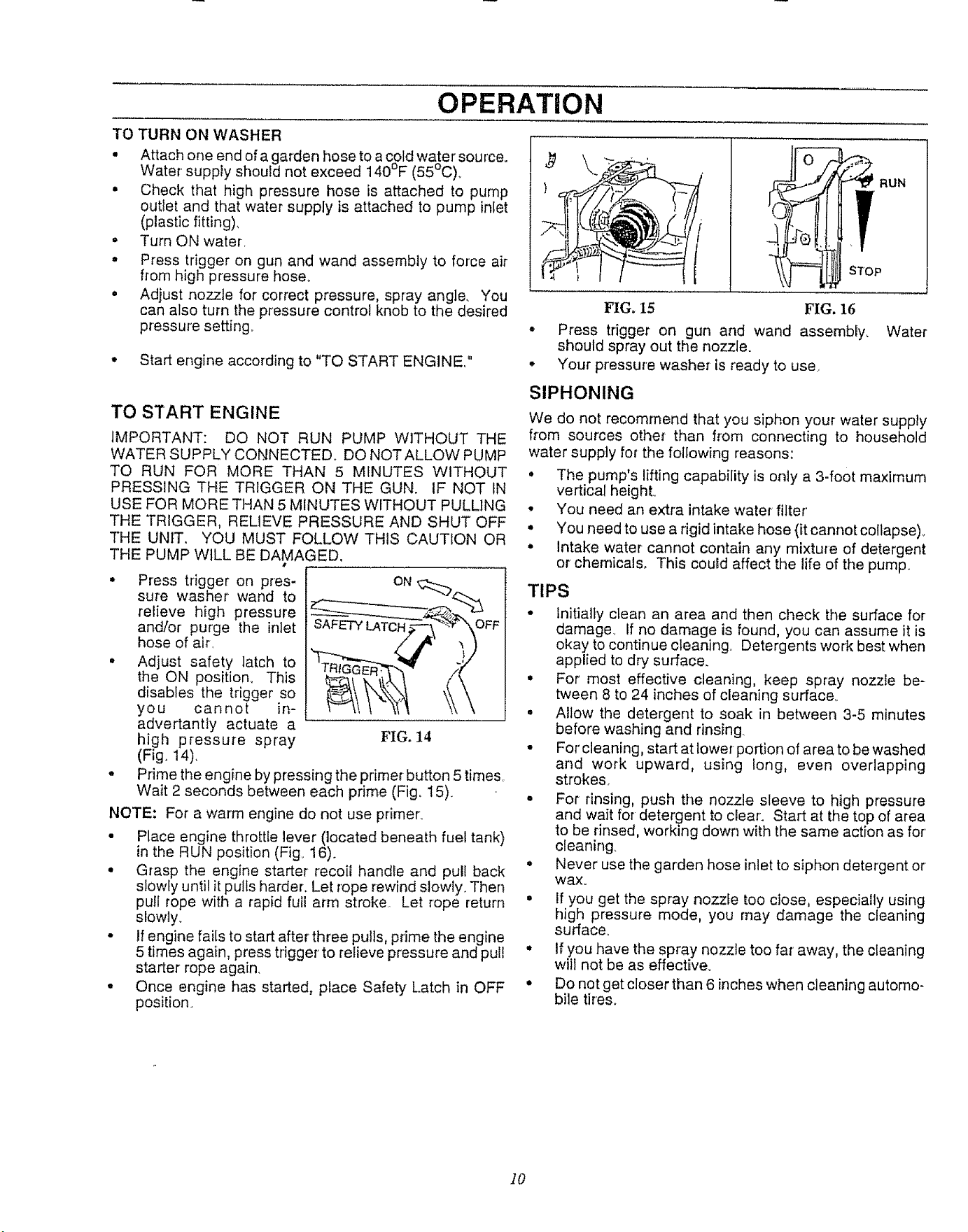
Press tdgger on pres-
sure washer wand to
relieve high pressure
and/or purge the inlet
hose of air.
Adjust safety latch to
the ON position.. This
disables the trigger so
you cannot in-
advertantly actuate a
high pressure spray
(Fig. 14).
ON
• Prime the engine by pressing the primer button 5 time&
Wait 2 seconds between each prime (Fig, 15)
NOTE: For a warm engine do not use primer.
• Place engine throttle lever (located beneath fuel tank)
in the RUN position (Fig_ 16).
° Grasp the engine starter recoil handle and pull back
slowly until it pulls harder. Let rope rewind slowly. Then
pull rope with a rapid full arm stroke. Let rope return
slowly.
• If engine fails to start after three pulls, prime the engine
5 times again, press trigger to relieve pressure and pull
starter rope again.
• Once engine has started, place Safety Latch in OFF
position.
FIG. 15 FIG. 16
° Press trigger on gun and wand assembly,
should spray out the nozzle.
° Your pressure washer is ready to use.
SIPHONING
Water
We do not recommend that you siphon your water supply
from sources other than from connecting to household
water supply for the following reasons:
• The pump's lifting capability is only a 3-foot maximum
vertical heighL
• You need an extra intake water filter'
• You need to use a rigid intake hose (it cannot co!lapse)_
° intake water cannot contain any mixture of detergent
or chemicals_ This could affect the life of the pumF
TIPS
• Initially clean an area and then check the surface for
damage, if no damage is found, you can assume it is
okay to continue cleaning. Detergents work best when
applied to dry surface.
° For most effective cleaning, keep spray nozzle be-
tween 8 to 24 inches of cleaning surface..
• Allow the detergent to soak in between 3-5 minutes
before washing and rinsing.
• For' cleaning, start at lower-portion of area to be washed
and work upward, using long, even overlapping
strokes.
° For rinsing, push the nozzle sleeve to high pressure
and wait for detergent to clear. Start at the top of area
to be rinsed, working down with the same action as for'
cleaning.
° Never use the garden hose inlet to siphon detergent or
wax.
° If you get the spray nozzle too close, especially using
high pressure mode, you may damage the cleaning
surface.
° If you have the spray nozzle too fat away, the cleaning
will not be as effective.
• Do not get closer than 6 inches when cleaning automo-
bile tires.
10
CUSTOMER RESPONSIBILHTHES
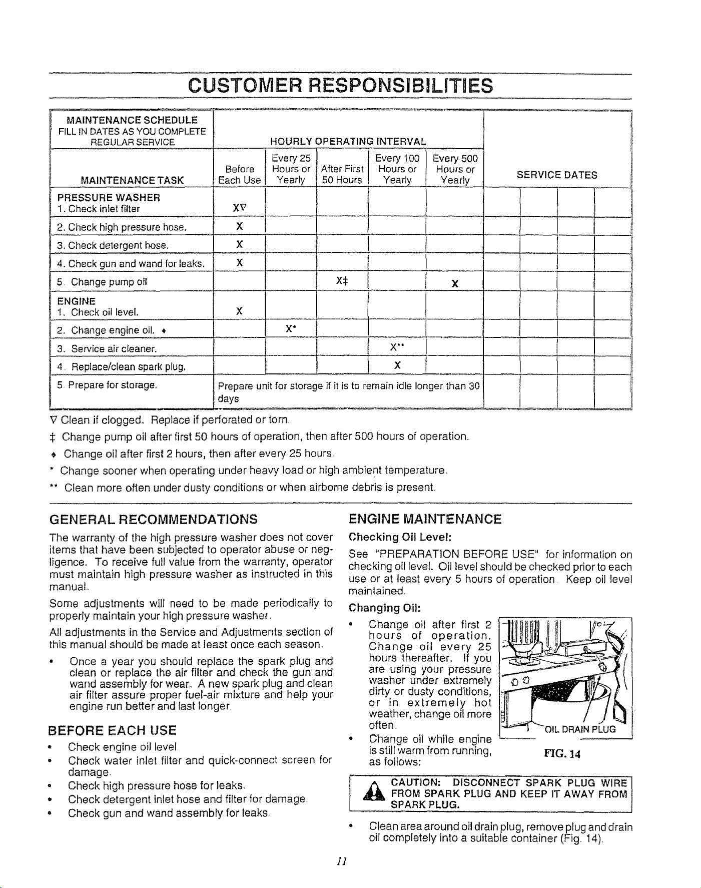
MAINTENANCE SCHEDULE
FILL IN DATES AS YOU COMPLETE
REGULAR SERVICE
MAINTENANCE TASK
PRESSURE WASHER
1. Check inlet filter
2. Check high pressure hose.
3. Check detergent hose.
4. Check gun and wand for leaks.
5 Change pump oil
ENGINE
1. Check oil level,
2. Change engine oil.
3. Service air cleaner.
4 Replace!clean spark plug,
5. Prepare for storage°
HOURLY OPERATING INTERVAL
Every 25 Every 500
Before Hours or Hours or
Each Use Yearly Yearly
XV
X
X
X
x
X
X*
Every I00
After First Hours or
50 Hours Yearly
X:I:
X *o
X
Prepare unit for storage if it is to remain idle longer than 30
days
V Clean if clogged° Replace if perforated or torn
Change pump oil after first 50 hours of operation, then after 500 hours of operation.
, Change oil after first 2 hours, then after every 25 hours,
" Change sooner when operating under heavy load or high ambient temperature,
** Clean more often under dusty conditions or when airborne debris is present,
SERVICE DATES
i
i
i
GENERAL RECOMMENDATIONS
The warranty of the high pressure washer does not cover
items that have been subjected to operator abuse or neg-
ligence. To receive full value from the warranty, operator
must maintain high pressure washer as instructed in this
manual°
Some adjustments will need to be made periodically to
properly maintain your high pressure washer
All adjustments in the Service and Adjustments section of
this manual should be made at least once each season.
Once a year you should replace the spark plug and
clean or replace the air filter and check the gun and
wand assembly for wear., A new spark plug and clean
air filter assure proper fuel-air mixture and help your
engine run better and last longer.
BEFORE EACH USE
* Check engine oi! level
o Check water inlet filter and quick-connect screen for
damage,
o Check high pressure hose for leaks,
* Check detergent inlet hose and filter for damage
° Check gun and wand assembly for leaks,
ENGINE MAINTENANCE
Checking Oil Level:
See "PREPARATION BEFORE USE" for information on
checking oil level, Oil level should be checked prior to each
use or at least every 5 hours of operation Keep oil level
maintained,
Changing Oil:
• Change oil after first 2
hours of operation.
Change oil every 25
hours thereafter, If you
are using your pressure
washer under extremely
dirty or dusty conditions,
or in extremely hot
weather, change oil more
often,
• Change oil while engine
is still warm from running,
as follows:
OIL DRAIN PLUG
FIG. 14
I A CAUTION: DISCONNECT SPARK PLUG WIRE
FROM SPARK PLUG AND KEEP IT AWAY FROM
SPARK PLUG.
° Clean area around oil drain plug, remove plug and drain
oil completely into a suitable container (Fig. 14),
]]
CUSTOMER RESPONSIBILITIES
Changing Oil (continued):
', When all oil has drained, install and tighten oil plug.
o Remove oil dipstick. Wipe dipstick clean
• Fill engine crankcase with recommended oil until oil
level is at "FULL" point on oil dipstick. Do not overfill
above that mark° About 20 ounces is required. POUR
SLOWLY°
o When engine crankcase is filled to proper level, install
and tighten oil dipstick.
Service Air Cleaner:
Your engine will not run properly and may be damaged if
you run it using a dirt,/air cleaner.
Clean or replace the air cleaner' paper filter once every 100
hours of operation or once a year, whichever comes firsL
first. Clean or replace more often if operating under dusty
or' dirty conditions. Replacements are available at your
local Sears Authorized Service Center.
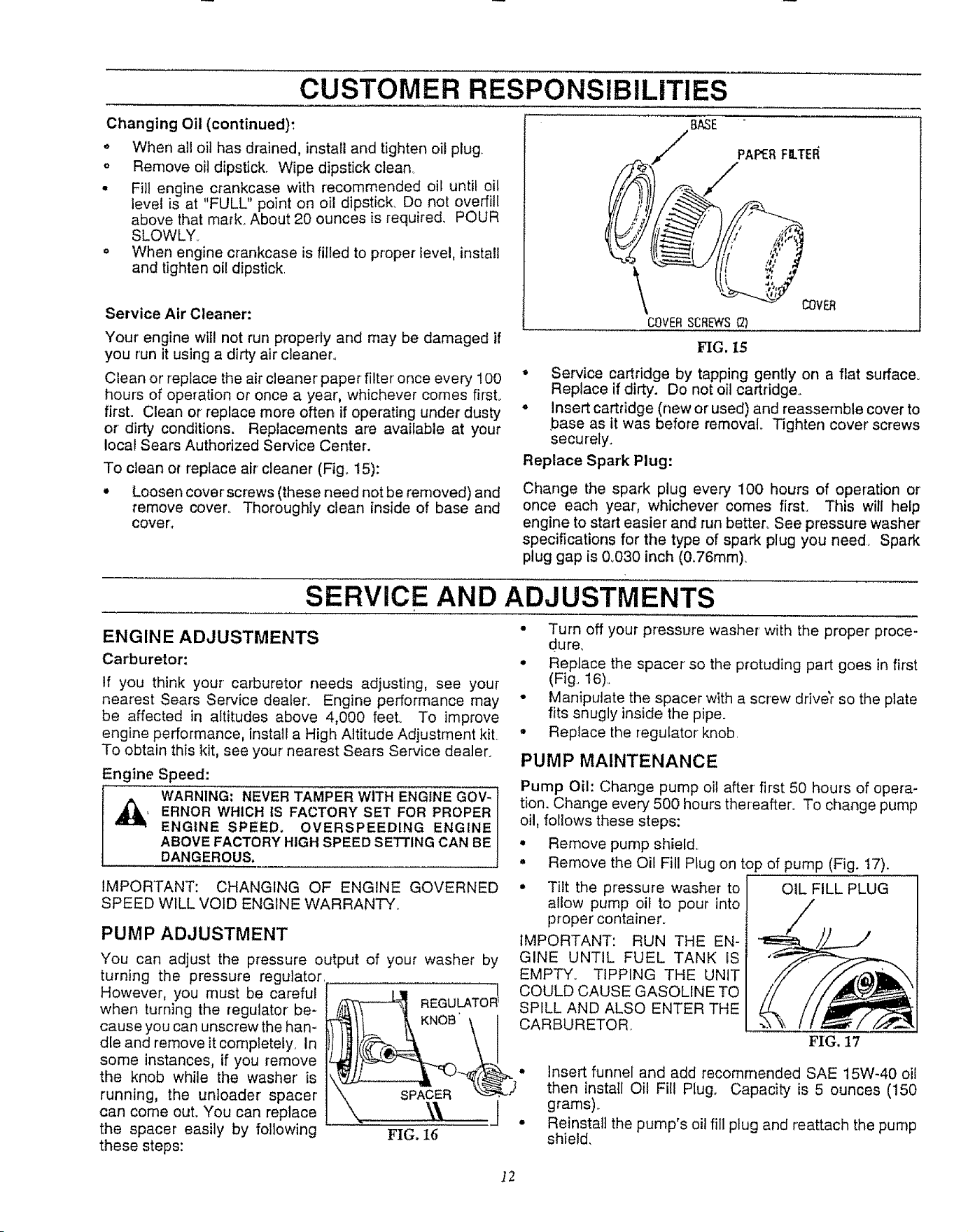
To clean or replace air cleaner (Fig. 15):
° Loosen cover screws (these need not be removed) and
remove cover. Thoroughly clean inside of base and
cover.,
BASE "
I.._/ PAPERFILTEI_
VER
COVERSCREWS{2)
FIG,15
,, Service cartridge by tapping gently on a flat surface.
Replace if dirty. Do not oil cartridge.
• Insert cartridge (new or used) and reassemble cover to
base as it was before removal Tighten cover screws
securely.
Replace Spark Plug:
Change the spark plug every 100 hours of operation or'
once each year, whichever comes first. This will help
engine to start easier' and run better, See pressure washer'
specifications for the type of spark plug you need. Spark
plug gap is &030 inch (0o76mm).
SERVICE AND ADJUSTMENTS
ENGINE ADJUSTMENTS
Carburetor:
If you think your carburetor needs adjusting, see your
nearest Sears Service dealer. Engine performance may
be affected in altitudes above 4,000 feet. To improve
engine performance, install a High Altitude Adjustment kiL
To obtain this kit, see your nearest Sears Service dealer.
Engine Speed:
WARNING: NEVER TAMPER WITH ENGINE GOV-
, ERNOR WHICH IS FACTORY SET FOR PROPER
ENGINE SPEED. OVERSPEEDING ENGINE
ABOVE FACTORY HIGH SPEED SETTING CAN BE
DANGEROUS.
iMPORTANT: CHANGING OF ENGINE GOVERNED
SPEED WILL VOID ENGINE WARRANTY.
PUMP ADJUSTMENT
You can adjust the pressure output of your washer by
turning the pressure regulator,
However, you must be careful
when turning the regulator be-
cause you can unscrew the han-
dle and remove it completely, In
some instances, if you remove
the knob while the washer' is
running, the unloader spacer
can come out. You can replace
the spacer easily by following
these steps:
• Turn off your pressure washer with the proper proce-
dure,
• Replace the spacer so the protuding part goes in first
(Fig. 16)..
• Manipulate the spacer with a screw driver so the plate
fits snugly inside the pipe.
° Replace the regulator knob.
PUMP MAINTENANCE
Pump Oil: Change pump oil after first 50 hours of opera-
tion. Change every 500 hours thereafter. To change pump
oil, follows these steps:
• Remove pump shield.
° Remove the Oil Fill Plug on top of pump (Fig. 17).
° Tilt the pressure washer to OIL FILL PLUG
allow pump oil to pour into /
proper container.
/
IMPORTANT: RUN THE EN-
GINE UNTIL FUEL TANK IS
EMPTY. TIPPING THE UNIT
! COULD CAUSE GASOLINETO
REGULATOR SPILL AND ALSO ENTER THE
_II_ _ KNOB \ 1 CARBIJRETOR'
\. _,l 1' grams). . .
\,. _I, J • Reinstall the pump's oil fill plug and reattach the pump
.t,lt_. J._ shield,
12
STORAGE
PRESSURE WASHER PUMP
Water should not remain in the unit for long periods of time.
Sediments of minerals can deposit on pump parts and
"freeze" pump action.. If you do not plan to use the Pressure
Washer for more than 30 days, follow this procedure:
• Flush detergent hose by placing the injector filter into
a pail of clear water while running Pressure Washer
with nozzle in tow pressure mode.. Flush for five min-
utes,
• Shut off the engine and let it cool, then remove all
hoses,
Place throttle lever in "STOP" position.
CAUTION: BE SURE THE THROTTLE LEVER IS IN
"STOP" POSITION BEFORE YOU CONTINUE. IF
YOUSTART THEENGINE WITHOUTTHE PROPER
WATER SUPPLY CONNECTED, YOU CAN DAM-
AGE THE PUMP.
o Empty the pump of all pumped liquids by pulling recoil
handle about 6 times, This should remove most of the
liquid in the pump.
NOTE: To protect the unit from freezing temperatures, you can draw
windshield washer fluid into the pump by pouring the washer fluid
Into a 3-foot section of garden hose connected to the inlet adaptor
and pulling the recoil handle twlce_
° Store in a clean, dry area_
ENGINE
WARNING: NEVER STORE ENGINE WITH FUEL IN
TANK INDOORS OR IN ENCLOSED, POORLY VEN-
TILATED AREAS WHERE FUMES MAY REACH AN
OPEN FLAME, SPARK OR PILOT LIGHT AS ON A
FURNACE, WATER HEATER, CLOTHES DRYER
OR OTHER GAS APPLIANCE.
It is important to prevent gum deposits from forming in
essential fuel system parts such as the carburetor, fuel
filter, fuel hose or tank during storage. Also, experience
indicates that alcohol-blended fuels (called "gasoho]" or
using ethanol or methanol) can attract moistu re which leads
to separation and formation of acids during storage. Acidic
gas can damage the fuel system of an engine while in
storage
To avoid engine problems, the fuel system should be
emptied before storage of 30 days or longer Follow these
instructions:
Drain Fuel System: Remove all gasoline from carburetor
and fuel tank to prevent gum deposits from forming on
these parts and causing possible malfunction of engine.
TAINER OUTDOORS, AWAY FROM OPEN FLAME.
BE SURE ENGINE IS COOL. DO NOT SMOKE.
• If you did use "gasohol", run engine until engine stops
from lack of fuelo Make sure you have water supply to
pump inlet connected and turned ON.
• Fuel stabilizer (such as STA-BIL ®) is an acceptable
alternative in minimizing fuel gum deposits during stor-
age.
Change Oil: While engine is still warm, drain oil from
crankcase_ Refill with recommended grade,
Oil Cylinder Bore: Remove spark plug and pour about 1/2
ounce (15ml) of engine oil into the cylinder_ Cover spark
plug hole with rag. Crank slowly to distribute oil.
t ,_ CAUTION' AVOID SPRAY FROM SPARK PLUG !
HOLE WHEN CRANKING ENGINE SLOWLY,
* Install spark plug,, Do not connect spark plug wire,
OTHER
o Do not store gasoline from one season to another,
° Replace your gasoline can if your can starts to rust,
Rust and/or dirt in your gasoline will cause problems_
o tf possible, store your unit indoors and cover it to give
protection from dust and dirt,,
• Cover you unit with a suitable protective cover that
does not retain moisture. Do not use plastic. Plastic
does not breathe, which allows condensation to form
and will cause your unit to rusL
IMPORTANT: NEVER COVER YOUR PRESSURE
WASHER WHILE ENGINE AND EXHAUST AREAS ARE
WARM.
]3
TROUBLESHOOTING
CAUSE CORRECTION
PROBLEM
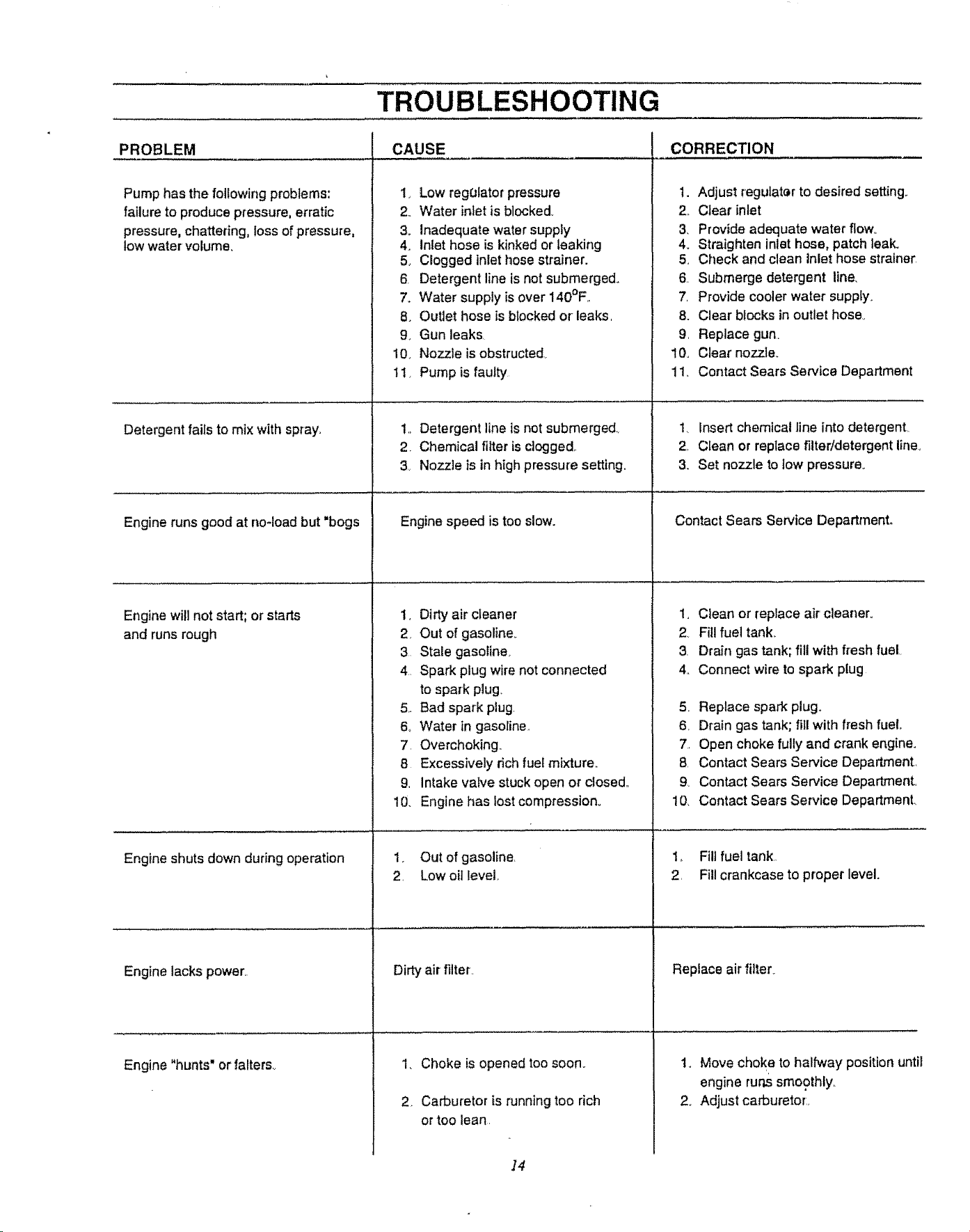
Pump has the following problems: 1_
failure to produce pressure, erratic 2o
pressure, chattering, loss of pressure, 3.
low water volume. 4.
5.
6.
7.
8.
9.
10.
11.
Detergent fails to mix with spray,
Engine runs good at no-load but "bogs
Engine will not start; or starts t,
and runs rough 2
Engine shuts down during operation
Engine lacks power,.
Engine "hunts" or falters_
Low regolator pressure
Water inlet is blocked.
Inadequate water supply
inlet hose is kinked or leaking
Clogged inlet hose strainer.
Detergent line is not submerged°
Water supply is over 140°E,
Outlet hose is blocked or leaks,
Gun leaks,
Nozzle is obstructed
Pump is faulty
1,, Detergent line is not submerged.,
2. Chemical filter is clogged,
3,, Nozzle is in high pressure setting.
Engine speed is too slow.
Dirty air cleaner
Out of gasoline.
3 Stale gasoline.
4 Spark plug wire not connected
to spark plug.
5. Bad spark plug,
6o Water in gasoline,
7, Overchoking.
8 Excessively rich fuel mixture.
9, Intake vatve stuck open or closed,,
10. Engine has lost compression_
1. Out of gasoline,
2, Low oil bevel,
Dirty air filter.
I, Choke is opened too soon.
2 Carburetor is running too rich
or too lean.
1. Adjust regulater to desired setting_
2. Clear inlet
3. Provide adequate water flowo
4. Straighten inlet hose, patch leak.
5. Check and clean Inlet hose strainer
6. Submerge detergent line,
7, Provide cooler water supply.
8. Clear blocks in outlet hose_
9, Replace gun,
l& Clear nozzle.
11. Contact Sears Service Department
t, Insert chemical line into detergent,.
2, Clean or replace filter/detergent line,
3. Set nozzle to low pressure.
Contact Sears Service Department,,
1. Clean or replace air' cleaner°
2. Fill fuel tank,.
3. Drain gas tank; fill with fresh fuel
4,, Connect wire to spark ptug
5, Replace spark plugo
6, Drain gas tank; fill with fresh fuel
7, Open choke fully and crank engine.
8, Contact Sears Service Department.
9 Contact Sears Service Department_
10, Contact Sears Service Department,
1_ Fill fuel tank
2, Fill crankcase to proper level.
Replace air filter.
t. Move choke to halfway position until
engine runs smoothly,
2. Adjust carburetor,,
]4
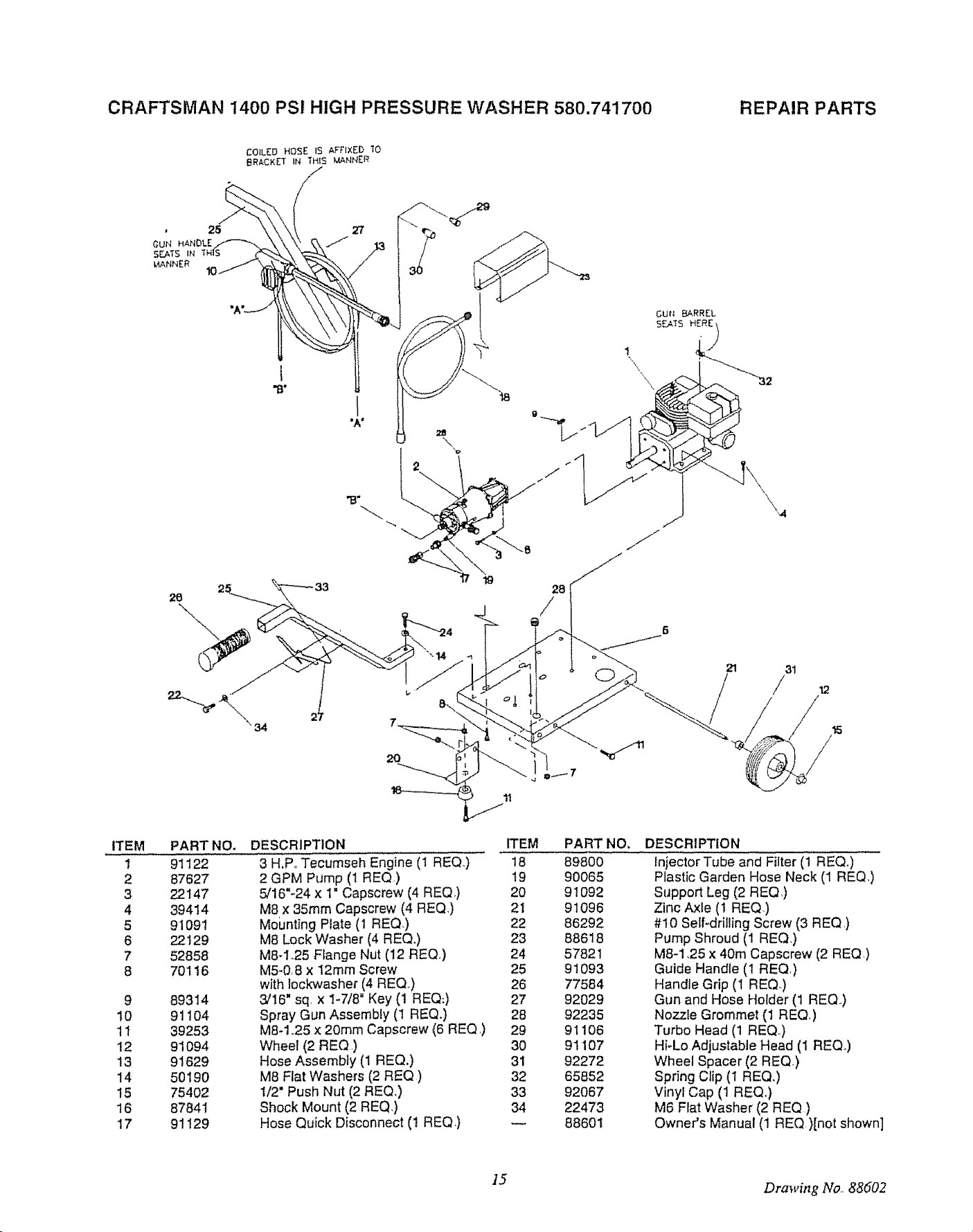
CRAFTSMAN 1400 PSI HIGH PRESSURE WASHER 580.741700 REPAIR PARTS
I
"B"
I
28
/
ITEM
1
2
3
4
5
6
7
8
9
10
11
12
13
14
15
16
17
PART
91122
87627
22147
39414
91091
22129
52858
70I 16
89314
91104
39253
91094
91629
50190
75402
87841
91129
NO.
DESCRIPTION ITEM PART NO,
3 H.Po Tecumseh Engine (1 REQ.,) 18 89800
2 GPM Pump (I REQ) 19 90065
5/16"-24 x 1" Capscrew (4 REQ) 20 91092
M8 x 35ram Capscrew (4 REQ,) 21 91096
Mounting Plate (1 REQ) 22 86292
M8 Lock Washer (4 REQ.) 23 88618
M8-1.25 Flange Nut (12 REQ.) 24 57821
M5-0,8 x 12mm Screw 25 91093
with Iock_asher (4 REQ°) 26 77584
3/16" sq. x I-7/8" Key (1 REQ:) 27 92029
Spray Gun Assembly (1 REQ.) 2B 92235
M8-1.25 x 20mm Capscrew (6 REQ,) 29 91106
Wheel (2 REQ ) 30 91107
Hose Assembly (1 REQ.) 31 92272
M8 Flat Washers (2 REQ ) 32 65852
1/2" Push Nut (2 REQ,) 33 92067
Shock Mount (2 REQ,) 34 22473
Hose Quick Disconnect (1 REQ,) -- 88601
DESCRIPTION
Injector Tube and Filter (1 REQ.)
Plastic Garden Hose Neck (1 REQ,)
Support Leg (2 REQ)
Zinc Axle (1 REQ,)
#10 Self-drilling Screw (3 REQ,)
Pump Shroud (1 REQ,)
M8-1,25 x 40m Capscrew (2 RE(D,)
Guide Handle (1 REQ,)
Handle Grip (1 REQ-)
Gun and Hose Holder (t REQ,)
Nozzle Grommet (1 REQ.)
Turbo Head (1 REQ)
HFLo Adjustable Head (1 REQo)
Wheel Spacer (2 REQ)
Spring Clip (1 REQ.)
Vinyl Cap (1 REQ,)
M6 Fiat Washer (2 REQ)
Owner's Manual (1 REQ.)[not shown]
15 Drawing No., 88602
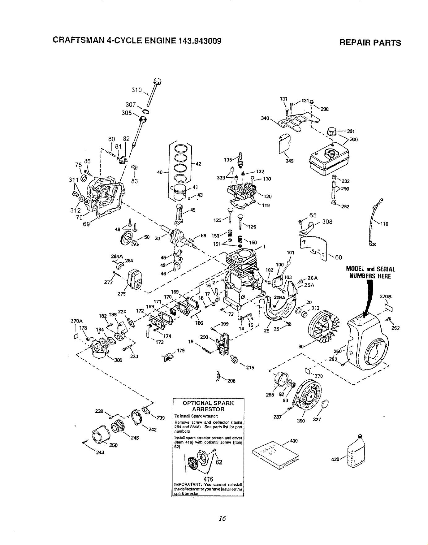
CRAFTSMAN 4-CYCLE ENGINE 143.943009 REPAIR PARTS
75
\
3tl
/
312
370A
86
172
182 18
\
184
_'174
173
179
186 <209 14
'_"215
MOOELendSERIAL
NUMBERSHERE
370B
262
15
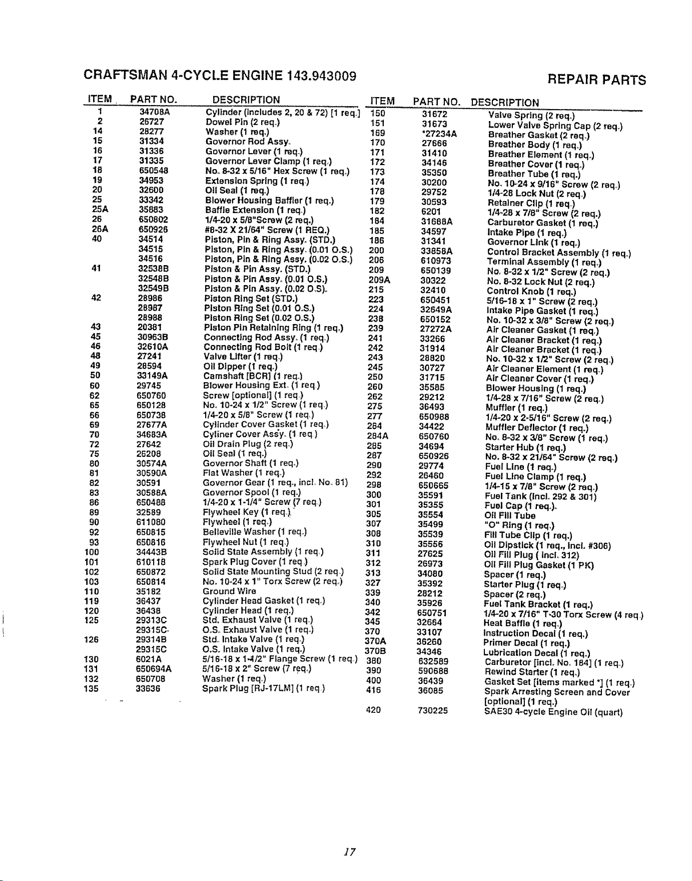
CRAFTSMAN 4-CYCLE ENGINE 143.943009
ITEM. PART NO.
1 34708A
2 26727
14 28277
15 31334
16 31336
17 31335
18 65O548
19 34953
20 32600
25 3.3342
25A 3.5883
26 650802
26A 650928
40 34514
34515
34516
41 325386
32648B
32549B
42 28986
28987
28988
43 20381
45 309636
46 32610A
48 27241
49 28594
50 33149A
60 29745
62 650760
65 650128
66 650738
69 27677A
70 34683A
72 27642
75 25208
80 30574A
81 30590A
82 30591
83 30588A
86 650488
89 32589
90 611080
92 650815
93 650816
100 34443B
101 510116
102 650872
103 650814
110 35182
119 36437
120 36438
125 29313C
29315C-
126 293146
29315C
130 6021A
131 650694A
132 650708
135 33636
DESCRIPTION ITEM PART NO.
Cylinder (Includes 2, 20 & 72) [1 req] 150 31672
Dowel Pin (2 reqo) 151 31673
169 "27234A
Washer (1 mq.)
Governor Rod Assyo t70 27666
Governor Lever (1 mq.) 171 31410
Governor Lever Clamp (1 req) 172 34146
No. 8-32 x 5/16" Hex Screw (t req.) 173 35350
Extenston Spring (1 raq.) 174 30200
Oil Seal (1 reqo) 178 29752
Blower Housing Baffler (1 req.) 179 30593
Baffle Extension (1 req_) 182 6201
t/4-20 x 518"Screw (2 mq.) 184 31666A
#8-32 X 21/64" Screw (I REQ,) 185 34597
Piston, Pin & Ring Assyo (STD,) 186 31341
Piston, Pin &Rtng Assy, (0o01 O,S,) 200 33858A
Piston, Pin & Ring Assy. (0.02 O._S.) 206 610973
Piston & Pin Assy. (STD.) 209 650139
Piston & Pin Assy. (0_01 O.S.) 209A 30322
Piston & Pin Assy. (0.02 O,S)o 215 32410
Piston Ring Set (STD.) 223 650451
Piston Ring Set (0_01 ORS.) 224 32649A
Piston Ring Set (0.,02 O,S,) 238 650152
Platen Pin Retaining Ring (1 req) 239 27272A
Connect|ng Rod Assy. (1 req_) 241 33266
Connecting Rod Bolt (t req) 242 31914
Valve Lifter (1 req.) 243 28820
Oii Dipper (I reqo) 245 30727
Camshaft [BCR] (1 req.) 250 31715
Blower Housing Exto (1 req) 260 35585
Screw [optional] (1 req) 262 29212
No. 10-24 x 112" Screw (1 req) 275 36493
1/4-20 x 5/8" Screw (t req) 277 650988
Cylinder Cover Gasket (1 reqo) 284 34422
Cyliner Cover As_yo (1 req) 284A 650760
Oil Drain Plug (2 req..) 285 34694
OilSeat (t req.) 287 650926
Governor Shaft (1 req_) 290 29774
Flat Washer (I req) 292 26460
Governor Gear (1 req., incl.. No., 81) 298 650665
Governor Spool (1 req.) 300 35591
1/4-20 x 1-1J4" Screw (7 req) 301 35355
Flywheel Key (1 req..). 305 35554
Flywheel (1 reqo) 307 35499
Bellevllie Washer (1 req) 308 35539
Flywheel Nut (1 req.) 310 35556
Solid State Assembly (1 req.) 311 27625
Spark Plug Cover (1 req ) 312 26973
Soiid State Mounting Stud (2 req.) 313 34080
Nee t 0-24 x 1" Torx Screw (2 req.,) 327 35392
Ground Wire 339 28212
Cylinder Head Gasket (1 req) 340 35926
Cylinder Head (1 req.) 342 650751
Sid. Exhaust Valve (1 req.) 345 32664
OoS. Exhaust Valve (1 req_) 370 33107
Std. intake Valve (1 req.) 370A 36260
O.S. Intake Valve (1 req.) 370B 34346
5/I6-18 x 1-.t/2" Flange Screw (1 req) 380 632569
5/I6*18 x 2" Screw (7 req_.) 390 590688
Washer (1 reqo) 400 36439
Spark Plug [RJ-17LM] (1 req) 416 36085
420 730225
REPAIR PARTS
DESCRIPTION
Va|ve Spring (2 req.)
Lower Valve Spring Cap (2 req.)
Breather Gasket (2 req.)
Breather Body (1 req.)
Breather Element (t req,,)
Breather Cover (1 req,)
Breather Tube (1 req.)
No., 10-24 x 9/16" Screw (2 req,)
1/4-28 Lock Nut (2 reqo)
Retainer Clip (1 req,,)
1/4-28 x 7/8" Screw (2 req.)
Carburetor Gasket (1 reqo)
Intake Pipe (1 req.)
Governor Link (1 reqo)
Control Bracket Assembly (1 req.)
Terminal Assembly (1 req3
No. 8"32 x 1/2" Screw (2 req.)
No. 8.32 Lock Nut (2 reqo)
Control Knob (1 req.)
5/15-18 x 1" Screw (2 req.)
Intake Pipe Gasket (1 req.)
No. 10_32 x 3/8" Screw (2 req..)
Atr Cleaner Gasket (1 reqo)
Air Cleaner Bracket (1 req.)
Air Cleaner Bracket (1 req.)
No. 10-32 x 1/2" Screw (2 req.)
Air Cleaner Element (1 req.)
Air Cleaner Cover (1 reqo)
Blower Housing (1 req,)
1/4-28 x 7/16" Screw (2 reqo)
Muffler (1 req.)
114-20 x 2-5/16" Screw (2 req.)
Muffler Deflector (t req.)
No. 8-32 x 3,/8" Screw (1 req_)
Starter Hub (1 req.)
No. 8"32 x 21/64" Screw (2 req_)
Fuel Line (1 reqo)
Fuel Line Clamp (1 reqo)
114-15 x 718" Screw (2 reqo)
Fuel Tank (tncL 292 & 301)
Fuel Cap (1 req.)_
O|1 Fill Tube
"O" Rtng (1 req,)
Fill Tube Clip (1 req.)
O|l Dipstick (1 req., IncL #306)
Oil Fill Plug ( tncl. 312)
Oil Fill Plug Gasket (1 PK)
Spacer (1 req.)
Starter Plug (1 re<l,,)
Spacer (2 req.)
Fuel Tank Bracket (1 req.)
1/4-20 x 7/16" T"30 Torx Screw (4 req)
Heat Baffle (1 reqo)
Instruction Decal (1 req.)
Primer Decal (1 req.)
Lubrication Decal (1 req.)
Carburetor [inci° Nee 184] (1 req_)
Rewind Starter (1 req_)
Gasket Set [items marked "] (1 req.)
Spark Arresting Screen and Cover
[optional] (1 req.)
SAE30 4-cycle Engtne Oil (quart)
17
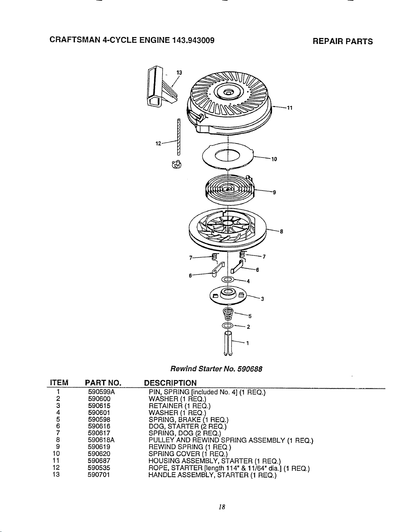
CRAFTSMAN 4-CYCLE ENGINE 143.943009
REPAIR PARTS
13
ITEM
1
2
3
4
5
6
7
8
9
10
1!
12
!3
Rewind Starter No. 590688
PART NO.
590599A
590600
590615
590601
590598
590616
590617
590618A
590619
590620
590687
590535
590701
DESCR!PTION
PIN, SPRING [included No_ 4] (1 REQ.)
WASHER (1 REQ.)
RETAINER (1 REQo)
WASHER (t REQ)
SPRING, BRAKE (1 REQ.)
DOG, STARTER (2 REQ.)
SPRING, DOG (2 REQ.)
PULLEY AND REWIND SPRING ASSEMBLY (1 REQ_)
REWIND SPRING (1 REQ)
SPRING COVER (1 REQ.)
HOUSING ASSEMBLY, STARTER (1 REQ_)
ROPE, STARTER [length 114" & 11/64" dia.] (1 REQ.)
HANDLE ASSEMBLY, STARTER (1 REQ_)
18
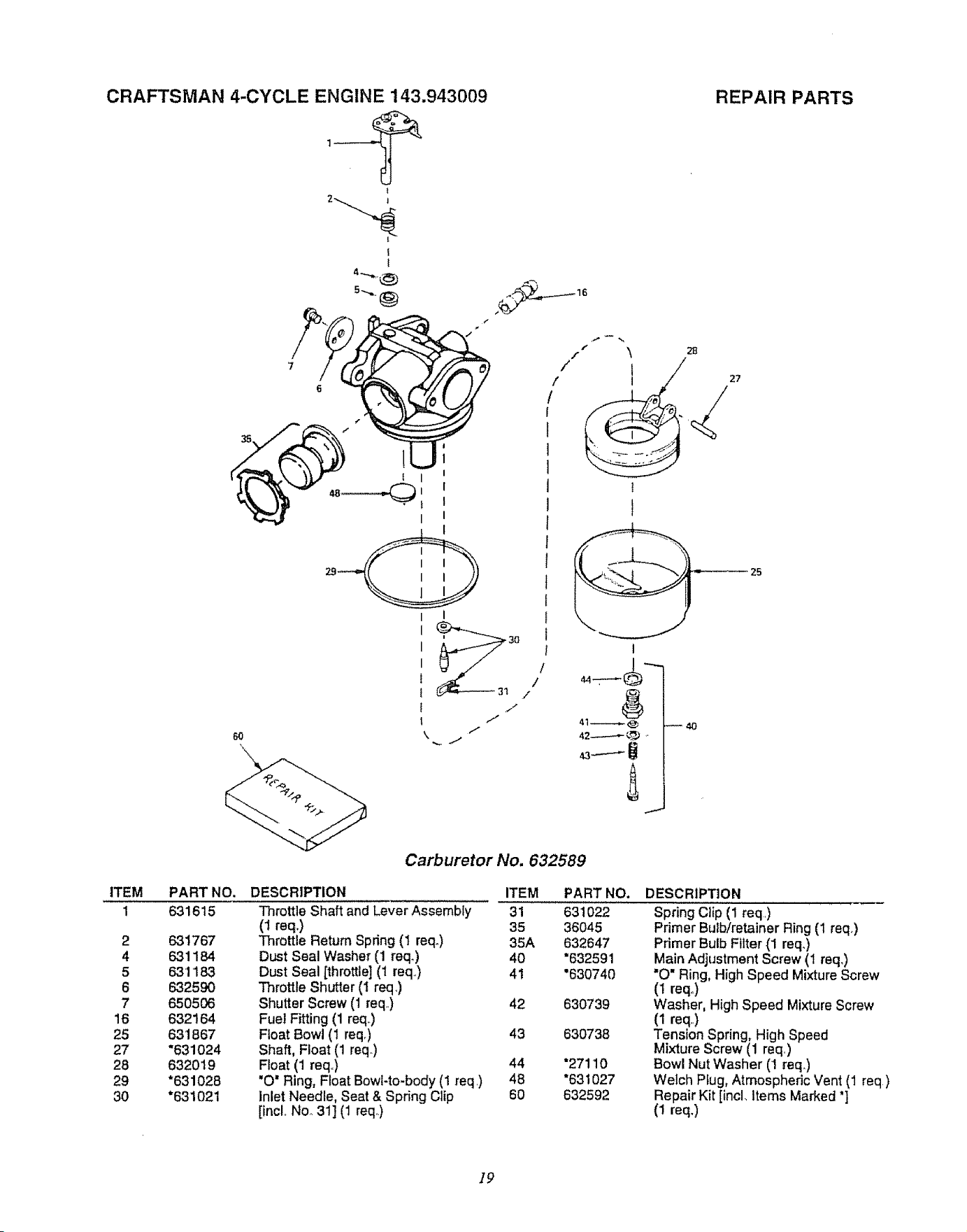
CRAFTSMAN 4-CYCLE ENGINE 143.943009
,____q
REPAIR PARTS
I
s"
/ \
f
!
/
/
/
t
)
I
f
2ft
27
ITEM
1
2
4
5
6
7
16
25
27
28
29
30
Carburetor No. 632589
PART NO,
631615
631767
6.31184
6.31'183
632590
650506
632164
631867
"631024
632019
"631028
"631021
DESCRIPTION ITEM
Throttle Shaft and Lever Assembly 31
(1 req,) 35
Throttle Return Spring (1 reqo) 35A
Dust Seal Washer (1 reqo) 40
Dust Seal [throttle] (1 req.) 41
Throttle Shutter (I req,)
Shutter Screw (1 req,) 42
Fuel Fitting (1 req.)
Float Bowl (1 req.) 43
Shaft, Float (1 req.)
Float (1 req.,) 44
"O" Ring, Float Bowl-to-body (1 req ,) 48
inlet Needle, Seat & Spring Clip 60
[incl. Noo 311 (1 req.)
PART NO.
631022
36045
632647
*63259 1
"630740
630739
630738
"27110
"631027
632592
DESCRtPTtON
Spring Clip (1 req,)
Primer Bulb/retainer Ring (1 req_)
Primer Bulb Fitter (1 req.)
Main Adjustment Screw (1 req.)
)O" Ring, High Speed Mixture Screw
(1 reqo)
Washer, High Speed Mixture Screw
(1 req,,)
Tension Spring, High Speed
Mixture Screw (1 req)
Bowl Nut Washer (1 req.)
Welch Plug, Atmospheric Vent (1 req)
Repair Kit [incl. Items Marked "]
(1 req.)
]9
OWNER'S
MANUAL
MODEL NO.
580.741700
IF YOU NEED
REPAIR SERVICE
OR PARTS
FOR REPAIR SERVICE CALL
THIS TOLL FREE NUMBER
1-800-4°REPAIR
(1-800-473-7247)
FOR REPLACEMENT PARTS
INFORMATION AND ORDER-
ING, C_LL THIS TOLL FREE
NUMBER:
1-800-FON-PART
(1-800-366-7278)
CRRFTSMRll
3 HORSEPOWER
1400 PSI
HIGH PRESSURE WASHER
Each High Pressure Washer has its own model number. Each engine has
itsown model number.
The model number for your pressure washer will be found on a decal
attached to the uniL
The model number for the engine will be found on the Blower Housing of
the engine adjacent to the spark plug_
All parts listed herein may be ordered through Sears, Roebuck and Co.
Service Centers and most Retail Stores.
WHEN ORDERING REPAIR PARTS, ALWAYS GIVE THE FOL-
LOWING INFORMATION:
• PRODUCT-- HIGH PRESSURE WASHER
e MODEL NUMBER-- 580.747100
e ENGINE PART NO, -- 143.943009
• PART NUMBER
• PART DESCRIPTION
Your Sears merchandise has added value when you consider that Sears
has service units nationwide staffed with Sears trained technicians...pro-
fessiofial technicians specifically trained on Sears products, having the
parts, tools and the equipment to ensure that we meet our pledge to you,
we service what we sell.
o
SEARS, ROEBUCK and CO,, Hoffman Estates, IL 60179 U.S.A.
Part No. 88601 Revision 0 (I11704) Printed in USA,,
MANUAL DEL
USARIO
MODELO NO.
580.741700
IIlNE_ DE ASISTEHC_
,,,,._ CLIENTE "... ;
_QUINA _VADOR-_, DE %.\
j .ALTAp._.,o. --_ MAQUINA LAVADORA DE
___'_ PRES' ON
1400 PSI
3 CABALLOS DE FUERZA
IJNEADE ASISTEKC[AHORAS
DEOPERACIOH
MO#,-FRI. 8 AM - 5 PM (CST)
Lea y Siga todas
las Normas de Seguridad
e instrucciones Antes
de Operar Este Equipo
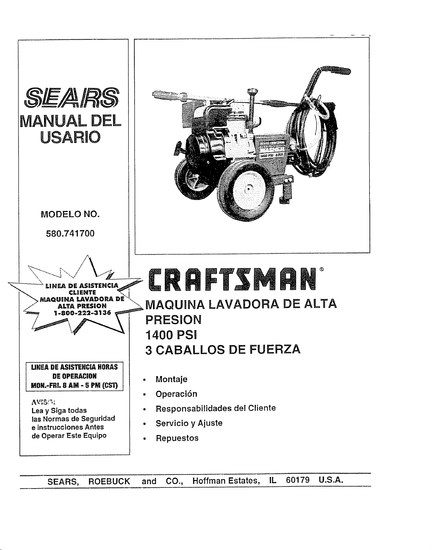
• Montaje
. Operaci6n
° Responsabitidades del Cliente
• Servicio yAjuste
• Repuestos
®
ALTA
SEARS, ROEBUCK and CO., Hoffman Estates, IL 60179 U.S.A.
REGLAS DE SEGURIDAD
AM]SO:MANTENGASIEMPREDESCONECTADOEL CABLE DELA BUJIA Y COLOQUELODONDENO PUEDA
TOCAR LA BUJIA,ESTO EVITARAQUE LA UNIDAD SE ENCIENDA'ACCIDENI_ALMENTECUANDOLA ESTE
INSTALANDO,TRANSPORTANDO,AJUSTANDO0 REPARANDO+
PRECAUClONES:
PREPARAClON:
• Losgases de escapedei motor contienengasde mon6xidede carbono
LETAL Este gas peligroso inhaladoen ciertas concentracionespuede
causerp_rdida del conocim_entoe inciuso _ muerte Opere esteequipo
sotoatairs libredondeextsiaventilaci6nadecuada
• La gesolinaes aliamente INFLAMABLEy sus vapores son EXPLOSt+
VOS No permitaque se fume, l+amasabiertas,chispaso calor en los
s+tioscercanos mientras este manejandola gasoline. Evitederramar
gasolinasobre el motor cuando esta caliente Permiia queta unidadse
enfrfe per 2 minutes antes de rettenarla+Cumplacon t(xJaslas normas
regulatoriaspareel almacenajeyet use de]a gasolina,
'= Sit0e esta m_,quinalavadora de presi6n en _eas lejanas a matedales
combustibles,vaporescombustibleso poivo
• El equipo de alta presi6n esta disenado pare set utJlizado_nicamente
con psrtesautorizadasper Sears El usuarioasumeredes los rtesgosy
responsabil+dadessi ut+lizaesteequipocon pa.rtesque no cumplancon
las especificacionesmfn+masy los dispositivosde seguridadde usedel
equipo
,D Algunosproductosqulmicoso detergentespuedenser petigrosossi son
inhatadoso tngeridos,causandonauseasevera,p_rdidade laconciencia
o envenenamientoEstosefementosde peligropueden causardaSoa fa
propiedady lesi6nsevere
_' No permitaque NI_.]OSoperen la M_quina Lavadota de Presi6n en
ning0nmemento
+
• Opereel motor,3nicamentea ia velocidadindicada+El hacerfuncionareli
motor a ve]ocidsdesexcesivaslncrementael riesgo de lesi6npersonal
No modifiqueotraspiezasdel motor que pudieranincrementaro dismi-
nuirla velocidadindicada
• No useropassuelias,joyerla o cuatquierrosa quepuedaquedarseatra-
padaen et arranqueoen otros rotores
.' Antes de encenderta M_quina Lavadorade Presibnen climefr{o, revise
todastas partesdel equipoyasegOresedequeno se haformadohielo
. Lasunidadescon partes rotes o perdidas,o sin caja de protecci6no cu-
biertasNUNCAdebenset operadas
• El silenctadory el depuradorde aJredeben ser insialsdosyen buenas
condicionesantes de operar la M;_,quinaLavadora de Presi6n Estos
componentesactOancomeatrapa chispassi el motorpeiardea
• Reviseque el sistemade combustibleno tengafugaso signosde deter..
iorocome unamangueradesgastadao esponjosa,abrazaderessuellaso
perdidaso daSoen e[ tanque o la iapa CortijaredesIondefectosantes
deoperarla M&quinaLavadorsde Presi6n
OPERAClON"
+ No rocie IIquidosinflamabies.
• Nuncadirijalapistola haciapersonas,animaleso plsntss
+, No permitaque ningunaparts entre en contactocon la corrientede flu-
ido.NOentre en contactocon la corrlentede fluidocreeds per una fuga
en tamanguerade alia presi6n
., La corriente de alia presi6n de fluido que puede producir este equipo
puede penetrar Is pie] y sus tejidos pro[undes,conllevandoa lesiones
seriesy posibleamputaci6n
• Elrodado de alia presi6npuedecauserquepa.,llculasde pinturau otras
partfcutasseenaerotra.qsporiadasy viajena alias velocidades.
a, Siempreuse protecci6nocular cuandoutiliceesleequipoo cuandoeste
proximoaJsitio deutiIizad6ndel equipo,
• Nuncautiticeuna presi6n superiorala presi6nde lluidoPSi clasificada
paresu m&quinslavadoradepresi6n
• Nuncamuevala m&quinatirandodela manguerade alia presi6n Utitice
elasa quese encuentraenfa parts superiordela unidad
,= Aseg0resesiemprede que Is pistolade rociado,boqui!lasy accesodos
est_ncorrectamenleconectados
• NuncauUliceuna pisloia derociadeque no tongaunseguropare el gatit-
Io,o unprotectorpars elgatillo colocadoyen buen funcionamiento
. Utiliceun respiradoro unam_soarasiemprequeexists el riesgode inha-
ler vapores Lea todas las inslruccbnes de la m,_scarade maneraque
usted se pueda asegurarde cluela m&scarale dar_,ta proteccbn nece-
sariaen centredela inhalaciSndevaporespeligrosos
,m Efrociadode alia presi6npueded_ar los eiementosfr,_giles,induyende
ei vidrk) No apunte la ptslolade rociado hacia el vidrio cuandoest_
usandoel rociadoa chorro,
., Mantengaia mangueraconectadaala m&quinao ta pistola de rociado
mientras e[ sistema esia siendo presurizado.Oesconeciarla manguera
mientrasest,. siendopresurizadaes pelkjroso+
=, Sostenga]a pistoiade rociadofirmementeen su maneantes de encend-
er la unidad Deno hacadoasi ]apistolspodr[aproducirun latigazopro-
vocando lestonesal ususrio No dejela pistela de rociadodesatendida
mlentrasla m_quinaesl_ funcionando
,D El _ea de iimpiezadebe tenorinclinacionesy drenajesaprepiadospars
reducirla posibIlidadde unacaldaa causade unasuperlicieresbalosa,
,= Mantenga el rociadedel ague tejosde lnslatacioneset_ctricasporq+Je
podr(aocasionarunadescargae_ctricafataJ
+, No ajuste ia v,_vulade de"_argaa una presi6nexcesivacon respectoa
la dasilicact6nde ta m_quina
= Noasegureel gatillode lapistolaenposici_nttas_ra(_[erta).
• Nopaso per alto ningOndispositivodesegurtdadenesia m_quina.
• Nodejeel gatiliocerradoper m_sde 5 minulos conei motoren funciona-
miento Estopoddada_iarlabomba+
• E] sitenciadory el motorse calientanduranle]aoperaot6ny permanecen
calientesinmediaiamentedespu_sdotapagado Evits el contactocon un
sitenciadoro motorcalienteo poddaresvllar enquemadurasseveras
MANTENIMIENTO Y ALMACENAJE:
o
Operey a_maceneesla unidadsobreunasuper[icieesiabte,
La manguers de alia presi6n puededesarroliar fugas per et desgaste,
enrroscamlento,abuse,etc Elague rociadade unafugaes capazde in+
troducir material dentro de la pteL Inspeccioneta manguera carla vez
antes de utilize:tie Revise todas las manguerasy observe si existen
codes, luges,abrasioneso protuberanciasde la cubierta,o daSoo movi-
mtentode los acoplamientos Reemplacainmediatarnentela manguerast
exLstecualquierade est_s condiciones Nunca intentsreparar la man-
guerade alia presi6n,Reempl_,celaconot_amangueraquereena lss cla-
sificacionesdepresi6nmlnimasde su m&qutnatavadoradepresi6n
BUSQUE ESTE SIMBOLO PARA SENALAR IMPORTANTES PRECAUCIONES DE SEGURI-
DAD+ESTO SIGNIFICA "iATENClONt!! iMANTENGASE ALERTA!!! SU SEGURIDAD ESTA
EN PELIGRO."
FELIClTAClONESpot su compra de la m_quina tavadorade afta
presi0nSearsCraftsman.,Estaha sidodise_ada,planeaday fabrica-
daparaproporcionarleIa mejorconfiabilidady desempeSoposibfe
Si tiene cualquierclase de problema que no puedaresolver f,%il-
mente,pot favorcontactesu CentroiDepartamentodeServicioSears
m&scercanooContamoscon t_cnicoscompetentesy bien entrena-
dos y con las herramientasapropiadaspara servire reparar esta
unidad
Pot favorlea y conserve este manual. Las instruccionesle capaci-
tar_,n para montar y mantener su generador apropiadamente.,
Siempreobservelas "REGLASDE SEGURIDAD"
NUMEROOEL
MODELO
NUMERODE
SERIE
580_741700
FECHADE
COMPRA
LOS NUMERODE[. MODELOY DE SERtESE ENCUENTRANENUNA
ETIQUETAADHERIDAA LAMAQUINALAVADORA.
USTEDDEBE ARCHIVARTANTO EL NUMERODE SERIECOMO LA
FECHA DE COMPRA Y MANTENERLOSEN UN LUGAR SEGURO
PARA FUTURASREFERENCIAS.
ACUERDO DE MANTENIMIENTO
Seencuentradisponibleun Acuerdode Mantenimientoen este pro-
ducto..Contactesu tiendaSearsm&scercanaparadetalles_.
RESPONSABIL1DADES DEL CLIENTE
,, Leay observetasregtasde seguridad.
• SigaunaprogramaciSnperi0dicaen el mantenimiento,cuidado y
usodesu m_quinalavadoradealta presi6n.
• Sigafasinstruccionesque se encuentranbajotassecciones"Re_
OnSabilidadesdel Cliente"y "Alrnacenaie'de este Manual de!
uario
ESPECIFICACIONES DEL PRODUCTO
Especificacionesdel la M_quinaLavadorade Presi0n
PRESION DE SALIDA
COEFIC1ENTEDE
FLUJO
MEZCLADE
DETERGENTE
TEMPERATURADEL
SUMINISTRO DE AGUA
ALTURADESUCCION
1400psi
"/_,5,Ipm
Utlllce deterq,ente sin dilulr
No e×ceder los 55c
90 cm. m_ximo
Especificaciones delMotor
CABALLOSDE FUERZA
NORMAL 3 HP
DESPLAZAMIENTO _adas_ cua_ (148cc) ......
BUJIA:Ttpo: Champion J-8C
Espacio establecido a
CAPACIDADDE
GASOLINA
ACEITE
o sfJ equivalente
0.030 pulgadas (0.76mm)
'1 Iltro aprox.
(600 ml. de capac!dad) _ Peso SAE 30
ESPACIODEAIRE DEIGNIClON
TRANSISTORtZADO 32 mm
-
Es requeridopotla ley un contrachispasen el Eslado deCalifornia
(SecciSn4442del C6digode RecursosP0blicosde Calitornia).Otros
estadospuedenlenerleyes similares Las leyesfederalesse aplican
a los terrenosfederales,
GARANTIA LIIVlITADA A UN AI_O DE LA MAQUINA LAVADORA DE ALTA PRESION CRAFSTMAN
Por un a_o a partir de ta fecha de compra, siempre y cuando esta M_quina Lavadora de Alta PresiSn sea mantenida y opera-
da de acuerdo alas instrucciones del manual det propietario, Sears reparar&, sin ning0n cargo, cualquier defecto en los mate-
riates y fa mano de obra..
Esta garant(a se apltcar_ solo por 90 alias si la M_.quina Lavadora de Alta PrestSn es uttlizada para prop6sitos comerciales o
para ser alquifada
Esta garant[a no cubre:
=, Elementos deteriorables
= Reparaciones necesarias debido a abuso o negligencia del operador, incl!._yendo el eje de la manivela y el incorrecto man-
tenimiento del equipo por no seguir las instrucctones contenidas en el manual def usuario,
EL. SERVIClO DE GARANTIA ESTA DISPONIBLE DEVOLVIENDO LA MAQUINA LAVADORA DE ALTA PRESION AL
CENTRO/DEPARTAMENTO DE SERVlCIO SEARS MAS CERCANO EN CUALQUIER PARTE DE LOS ESTADOS UNIDOS.
Esta garantfa le otorga derechos legales y tambi_n podr[a tener derechos adicionales, los cuales pueden varlar de estado a
estado
SEARS, ROEBUCK and CO., D/817 WA, Hoffman Estates, IL 60179
3
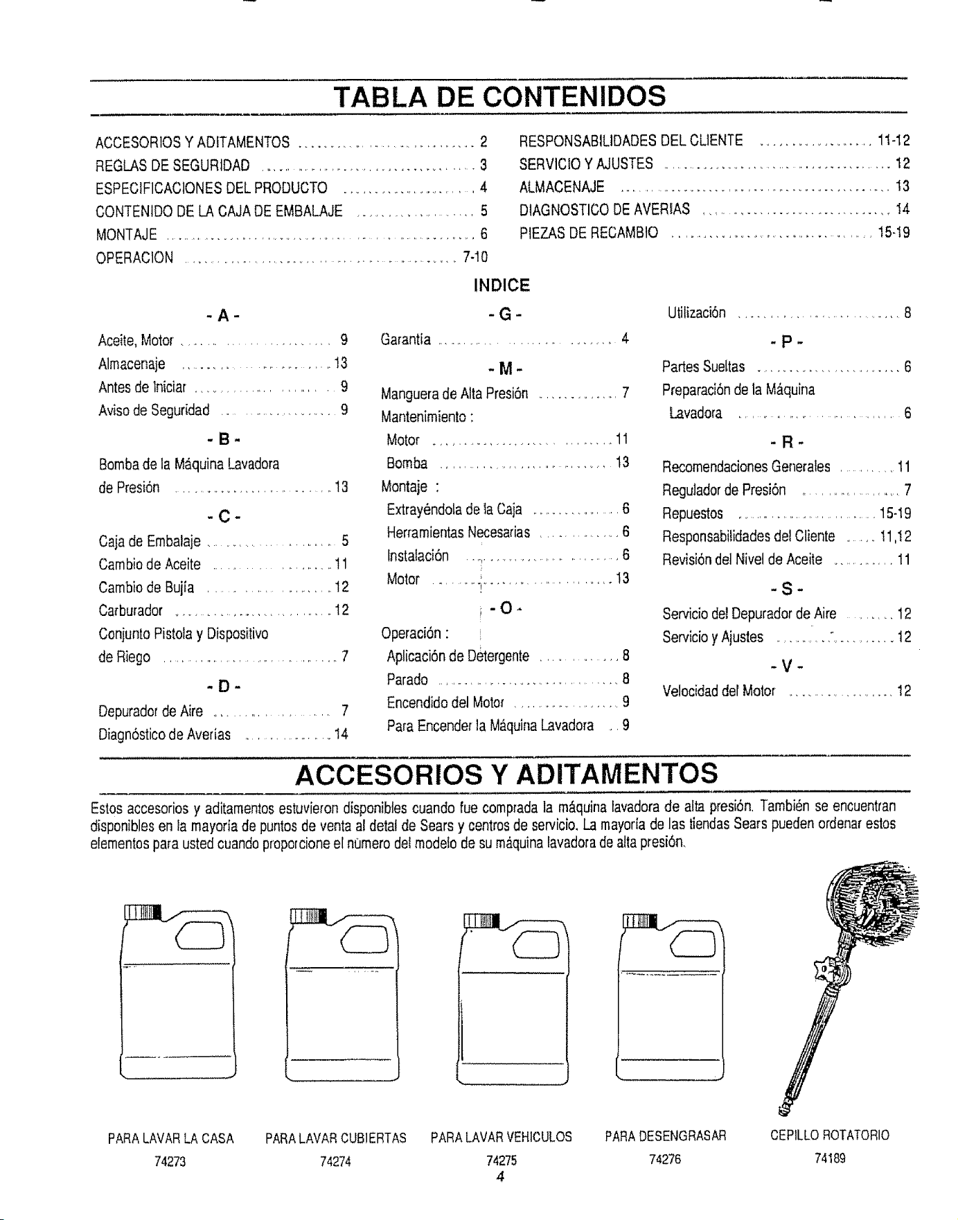
TABLA DE CONTENIDOS
ACCESORIOSY ADITAMENTOS.................................. 2
REGLASDE SEGURIDAD .......................................... 3
ESPECIF1CACIONESDELPRODUCTO ......................... 4
CONTENIDODE LACAJADE EMBALAJE ..................... 5
MONTAJE ............................................................ 6
OPERAC1ON ..................................................... 7-10
RESPONSABILIDADESDEL CUENTE ................... 1!-12
SERV1CIOY AJUSTES ............................................ 12
ALMACENAJE ................................................... !3
DIAGNOSTICODEAVERIAS ................................ 14
PtEZASDE RECAMBIO ....................................... t5-I9
INDICE
-A-
Aceite,Motor. ........................ 9
Almacenaje .............................. !3
Antesde lniciar , ...................... 9
Avisode Seguridad ........................ 9
-B-
Bombade la M_,quinaLavadora
de Presi6n ............................... 13
-C-
Caiade Embalaje .......................... 5
Cambiode Aceite ....................... 11
Cambiode Bujia ..................... 12
Carburador ............................... 12
Conjun_oPistolay Dispositivo
deRiego ................................... 1
-D-
DepuradordeAire ........................ 7
Diagn6sticode Averias .................... 14
-G-
Garantia ................................ 4
- !_/1 -
Manguerade AliaPresi6n ............... 7
Mantenimiento"
Motor ................................. 11
Bomba ................................... 13
Montaje •
Extray6ndolade iaCaja .................... 6
HerramientasNecesadas................. 6
fnstalaci6n ................................... 6
Motor ' 13
........... i ........................
i'O"
Operaci6n•
Aplicaci6nde Detergente ............... 8
Parado ........................................ 8
Encendidodel Motor ........................ 9
ParaEncenderla M_.quinaLavadora ,. 9
Utilizaci6n .................................. 8
.p.
PartesSueLtas ........................ 6
Preparaci6nde la M&quina
Lavadora ................................ 6
-R-
RecomendacionesGenerales ............. 11
Reguladorde Presi6n ........................ 7
Repuestos ......................................15-19
Responsabilidadesde] Cliente ........11,12
Revisi6ndel Nivelde Aceite .............. 11
"S"
ServiciodelDepuradorde Aire ......... 12
Servicioy Ajustes 12
-V-
Velocidaddel Motor .................... 12
ACCESORIOS Y ADITAMENTOS
Estosaccesoriosy aditamentosestuvierondisponiblescuando rue compradala m_quinalavadorade aita presi6n,Tambi_nse encuentran
disponiblesen la mayoriade puntosde ventaal detalde Sears y centrosde servicio,La mayoriade las tiendasSears puedenordenarestos
elementosparaustedcuandoproporcioneel numerodelmodelode su m,_quinalavadoradea!Iapresi6n.
PARALAVARLA CASA PARALAVAR CUB1ERTAS PARALAVARVEHICULOS PARADESENGRASAR CEPILLOROTATORIO
74273 74274 74275 74276 74t89
4
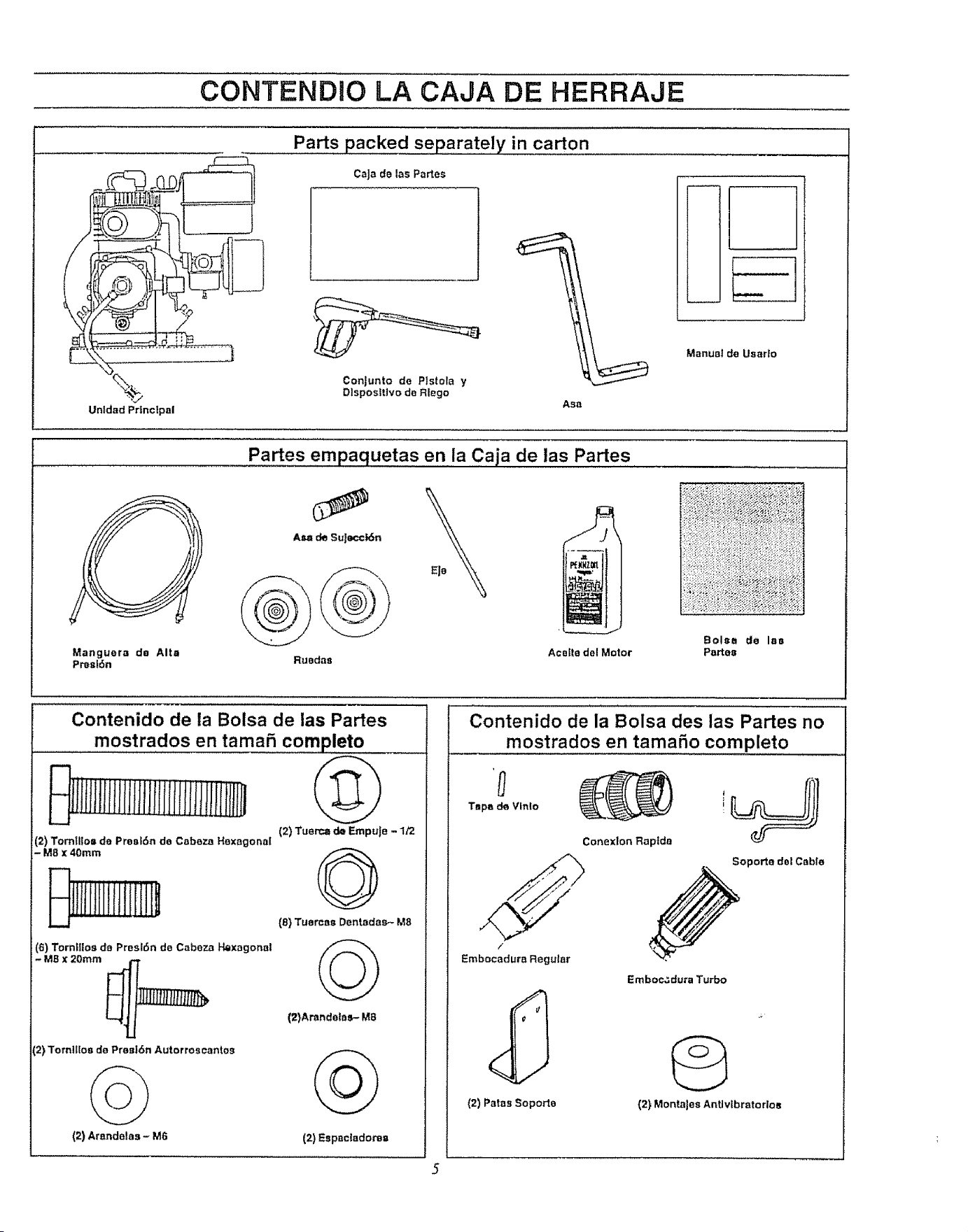
CONTENDIO LA CAJA DE HERRAJE
\
Unldad Principal
Parts packed separately in carton
CaJade las Partes
Conjunto de Plstola y
Dlsposlttvo de Rlego
I
Manual de Usarlo
Asa
Partes empaquetas en ia Caja de las Partes
Manguera de Alta
Prest6n
}
Balsa do laa
Aceffa del Motor Partes
Contenido de la Balsa de las Partes
mostrados en tama5 completo
iIIHttllfHI(!
(2) Tom!llo= do ProsL6n do Cabaza Hexagonal
- M8 X 40ram
(6) Torn|llos de Proslgn de Cabeza Hexagonal
- MB x 20ram _[_r_
(2) TomffIos do Pres|6n Autorroscantos
(2) Arnndelas - M6
(2) Tuert_ de Empule - 1/2
@
(8) Tuarcaa Dentodas- M8
©_)
(2)Arandalos- M8
(2) Espnc(aclorsa
Contenido de la Balsa des las Partes no
mostrados en tamafio completo
Tapa de Vlnlo i
Conex_on Raptda
/
Embocadura Regular
Emboc,_dura Turbo
(2) Paras Soporta (2) Manta)as ArtUvtbratorloa
MONTAJE
Lea esl_t.sinstruccionesy el Manualdel Opetadoren su tolalidad antes de
intenlar monlat u operar su nuevam_.quinalavadora de alia presi6n. Su
m_quinalavadorade alia presi6nha sidemontadacasl en su totalicladen la
f_brica,exceplu_do aquellas partesdejades sln monlar, Antes que usted
puedaoperarsu m_quinalavadorade alia presi6ndebe monlar eljuogo de
ruedasy conectarapropiadamenlelamangueradealia presi6n,
HERRAM1ENTAS REQUERIDAS PARA EL
MONTAJE
,_ Martillo
* Llavedecubecon Cubesde ll2-pulgada o 13 mm
,, LlavesAjustabteso Llavesde Combinaci6n
PARA EXTRAER LA MAQUINA LAVADORA DE
PRESION DE LA CAJA
, Retirarla agarraderagula (envueltaen pl_stico)
,, RelirarIa cajade accesoriosde la caja
o Retirarel grupo de piezas de la pistola y el dispositivede riego det
tableroportatarjetas
, Retirarlode et resto de maleriaJde empaquede la caja antes de relirar
su m&quinalavadorade altapresi6n
COMe COLOCAR SU MAQUINA LAVADORA DE
ALTA PRESTON PARA INSTALAR EL JUEGO DE
RUEDAS
Parala instalaci6nde! juego de ruedasse tequierentas hertamlentaslista-
das anleriormentey los elemenlos incluidosen la caja de accesoriosy el
asagu[a _'
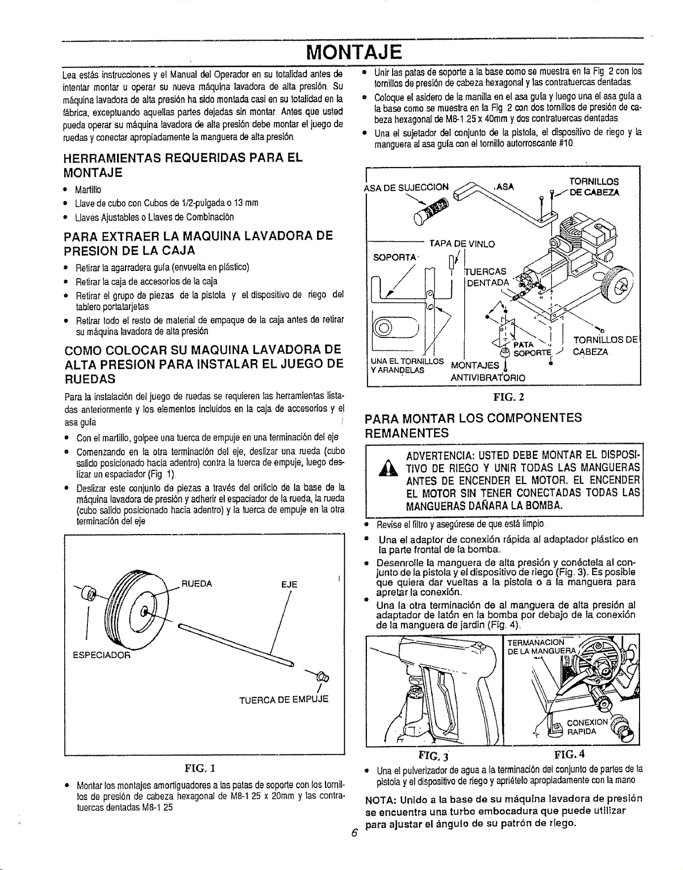
" Con el martitlo,gotpeeuna tuercade empujeen unalerminaci6ndel eje
* Comenzandoen la otra terminaci6ndet eie, deslizar una rdeda (cube
salidoposicionadohaciaadenlro) contfa la tuercade ernpuje,luego des-
lizar unespaciador(Fig. 1).
* Deslizat esle conjunto de piezas a trav6s det erificio de la base de la
m_.quinalavadoradepresi6ny adherirel espaciadordela rueda,]a rueda
(cubesalido posicionadohaciaadentro) y la luerca de empuje en la otra
lerminaci6ndefeje
ESPECtADOR
EJE
/
TUERCA DE EMPUJE
FIG. 1
Montarlosmonlaiesamorliguadoresa Iaspalas de soporteconlos tomil-
los de presi6nde cabeza hexagonalde M8-125 x 20mm y las contra-
tuercasdentadasM8-! 25
, Unit lasparasdesoporte a la base comeso mueslra en la Fig 2 con los
tomillosdepresi6ndecabeza hexagonaly las contraluercasdenladas
• Coloqueel asiderodela manillaen el asa gulay luegouna el asagula a
la basecome se muestra enla Fig 2 condos tomillosdepresi6nde ca.
bezahexagonaJdeM8-! .25x 40rnmy doscontraluercasdentadas
• Una el sujetadordal conjuntode la pistola, el disposilivo de riego y la
mangueraal asagufacon el torntlloautorroscanle#10
r
ASA DE SUJECCION
,ASA TORNILLOS
CABEZA
SOPORTA ,
TAPA DEVINLO
DENTADA
6
[
'-,,./ TORNiLLOS DE
SOPORTE.J CABEZ-A
UNA EL TORN1LLOS MONTAJES
Y AP,.ANDELAS
ANTIVIBRATORIO
FIG. 2
PARA MONTAR LOS COMPONENTES
REMANENTES
ADVERTENClA: USTED DEBE MONTAR EL DISPOS[-]
TIVO DE RIEGO Y UNIR TODAS LAS MANGUERAS]
ANTES DE ENCENDER EL MOTOR. EL ENCENDER 1
EL MOTOR SIN TENER CONECTADAS TODAS LASI
MANGUERASDA_ARA LA BOMBA. l
• Reviseelfillro y aseg0msedeque eslD,limpio
t Una et adaptor de conexi6n r_lpida al adaptador pl_stico en
ta parte frontal de la bomba.
,= Desen[olle la manguera de alta presi6n y con6ctela al con-
junto de la pistola y el dispositivo de riego (Fig. 3)° Es posible
que quiera clar vueltas a la pistola o a la manguera para
apretar la conexi6n.
Iit
Una la otra terminaciOn de al manguera de alta presi6n al
adaptador de lat6n en la bomba per debajo de la conexi6n
de la manguera de jardin (Fig. 4)_
TERMAIq_,CION
DE LA MANGUERA
CONEX1ON
RAPtDA
FIG, 3' FIG. 4
• Una etpulvei'izadorde aguaa la termtnaci6ndel conjuntodeparlesde la
pistolay el dispositivoderiego y apri_leloapropiadamentecon la mane
NOTA: Unldo a la base de su m_qutna lavadora de presibn
se encuentra una turbo embocadura que puede utilizar
para ajustar el &ngulo de su patr6n de rlego.
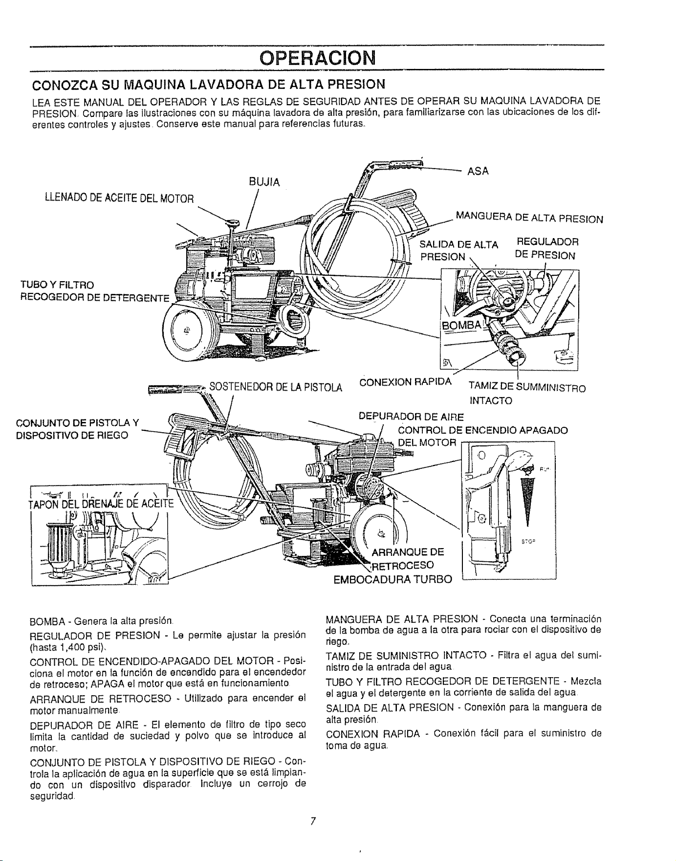
OPERACION
CONOZCA SU MAQUINA LAVADORA DE ALTA PRESION
LEA ESTE MANUAL DEL OPERADOR Y LAS REGLAS DE SEGURtDAD ANTES DE OPERAR SU MAQUINA LAVADORA DE
PRESION, Compare las ilustraciones con su m&quina lavadora de alta presi6n, para famitiarizarse con las ubicaciones de los dif-
erentes controles y ajustes, Conserve este manual para referenclas futuraso
LLENADODEACEITEDELMOTOR
BUJIA
ASA
MANGUERA DE ALTA PRESION
SALIDA DE ALTA REGULADOR
PRESION DE PRESION
TUBe Y FILTRO
RECOGEDOR DE DETERGENTE
CONJUNTO DE PISTOLA Y
DtSPOSITIVO DE RIEGO
SOSTENEDORDELA PISTOLA
CONEXION RAPIDA TAMIZ DE SUMMINISTRO
INTACTO
DEPURADOR DE AIRE
CONTROL DE ENCENDIO APAGADO
DEL MOTOR
ARRANQUEDE
;ESO
EMBOCADURATURBO
BOMBA - Genera Ia alia presi6n,
REGULADOR DE PRESION - Le permite ajustar fa presi6n
(hasta 1,400 psi),
CONTROL DE ENCENDIDO-APAGADO DEL MOTOR - Pesi-
ciona el motor en la funci6n de encendido para el encendedor
de retroceso; APAGA el motor que est& en funcionamiento
ARRANQUE DE RETROCESO - Utilizado para encender el
motor manualmente.
DEPURADOR DE AtRE - El elemento de filtro de tipo seco
limita la cantidad de suciedad y polvo qua se introduce al
motor,,
CONJUNTO DE PISTOLA Y DlSPOSlTIVO DE RIEGO - Con-
trola la aplicaci6n de agua en la superficie que se est& limpian-
do con un dispositivo disparador Incluye un cerrojo de
seguridad
MANGUERA DE ALTA PRESION - Conecta una terminaci6n
de la bomba de agua a la otra para rociar con el dispositivo de
dego.,
TAMIZ DE SUMINISTRO fNTACTO - Filtra el agua det sumi-
nistro de la entrada del agua
TUBe Y FILTRO RECOGEDOR DE DETERGENTE - Mezcla
el agua y el detergente en la corrienle de salida del agua
SALIDA DE ALTA PRESION ° Conexi6n para la manguera de
afta presi6n
CONEXtON RAPIDA - Conexi6n f_cil para el suministro de
toma de agua,
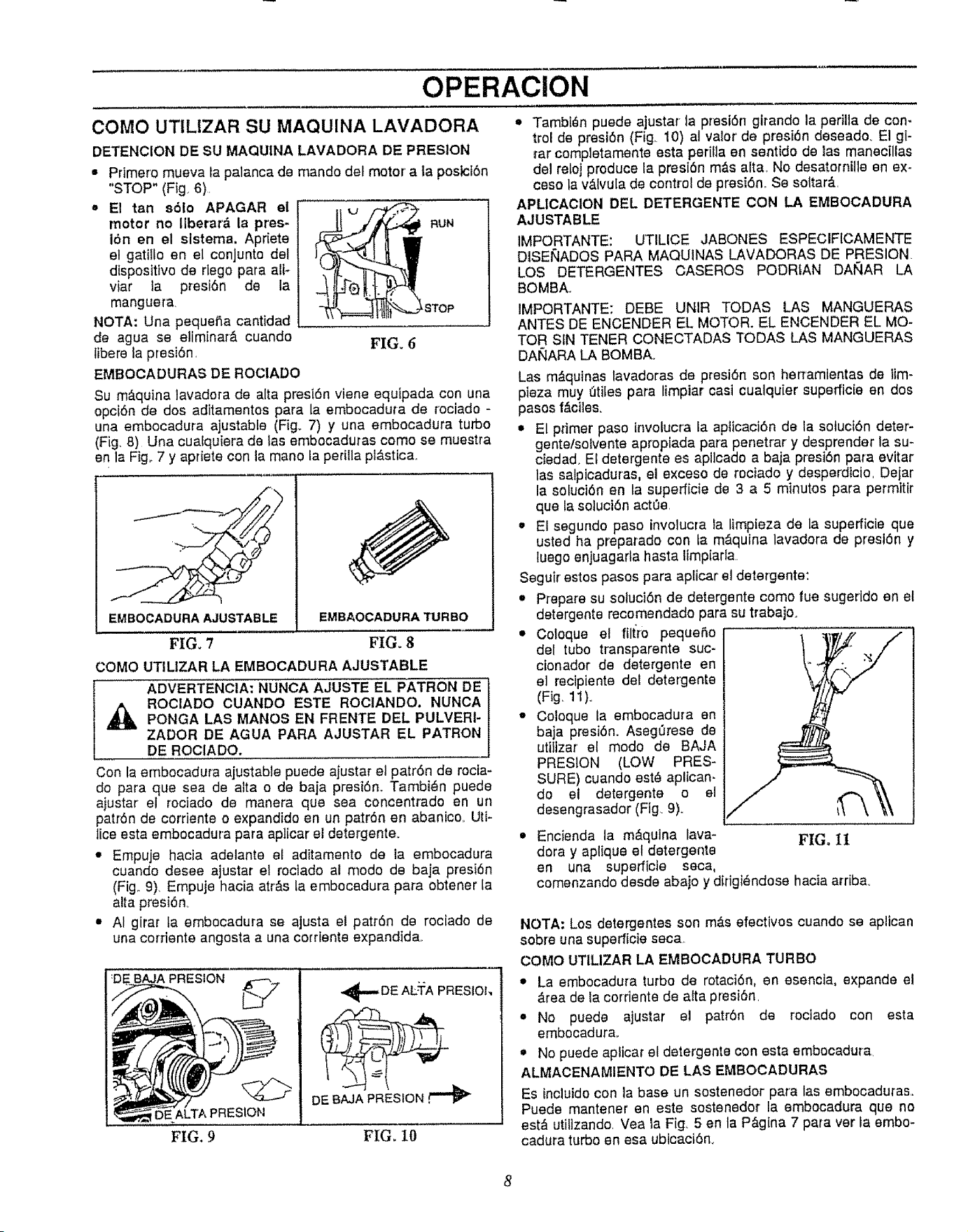
OPERAClON
COMO UTILIZAR SU MAQUINA LAVADORA
DETENCION DE SU MAQUINA LAVADORA DE PRESION
= Primero mueva ta palanca de mando det motor a ta postcf6n
"STOP" (Fig. 6).
= E1 tan s61o APAGAR el
motor no llberar_ la pres- F_UN
16n en el slstema. Apriete
el gatilto an el conjunto del
disposittvo de rlego para all-
viar ia presi6n de la
mangue_'a _STOP
NOTA: Una pequefla cantidad
de agua se eliminar& cuando FIG. 6
Iibere la presi6n,
EMBOCADURAS DE ROCIADO
Su m_quina lavadora de alta presi6n viene equipada con una
opci6n de dos aditamentos para la embocadura de rociado -
una embocadura ajustable (Fig° 7) y una embocadura turbo
(Fig. 8) Una cualquiera de tas embocaduras come se muestra
en la Fig,. 7 y apriete con la mane la periila plAstica,
EMBOCADURA AJUSTABLE EMBAOCADURATURBO
FIG. 7 FIG. 8
COMO UTILIZAR LA EMBOCADURA AJUSTABLE
ADVERTENClA: NUNCA AJUSTE EL PATRON DE
ROClADO CUANDO ESTE ROClANDO. NUNCA
PONGA LAS MANOS EN FRENTE DEL PULVERI-
ZADOR DE AGUA PARA AJUSTAR EL PATRON
DE ROCIADO.
Con la embocadura ajustable puede ajustar el patr6n de rocia-
do pare que sea de alta o de baja presi6n. Tambi_n puede
ajustar el rociado de manera que sea concentrado an un
patr6n de corriente o expandido an un patr6n en abanico,, Uti-
lice esta embocadura para aplicar el detergente_
* Empuje hacia adelante et aditamento de ta embocadura
cuando desee ajustar el rociado af mode de baja presi6n
(Fig,. 9). Empuje hacia atrhs Laembocedura para obtener la
atta presi6no
e AI girar ta embocadura se ajusta el patr6n de rociado de
una corriente angosta a una corrlente expandid&
. BAJA PRESION
PRESION
-_,,, DEALTA PRESIOh,
DE BAJA PRESTON
FIG, 9
FIG. IO
= Tambt_n puede ajustar la presI6n glrando la perilla de con-
trol de presi6n (Fig. 10) al valor' de presi6n deseado_ El gi-
tar completamente esta perilla en sentido de las manec[llas
del reloj produce la presi6n m&s alta, No desatornille en ex-
ceso ta v_,tvu[a de control de presi6n,. Se setter&
APLIOAOION DEL DETERGENTE CON LA EMBOCADURA
AJUSTABLE
IMPORTANTE: UTILICE JABONES ESPECIF[CAMENTE
DISEIrqADOS PARA MAQUINAS LAVADORAS DE PRESION.
LOS DETERGENTES CASEROS PODRtAN DAIqAR LA
BOMBA.
IMPORTANTE: DEBE UNIR TODAS LAS MANGUERAS
ANTES DE ENCENDER EL MOTOR. EL ENCENDER EL MO-
TOR SIN TENER CONECTADAS TODAS LAS MANGUERAS
DAtqARA LA BOMBA_
Las m&quinas lavadoras de presi6n son herTamientas de iim-
pieza muy dtites para limptar casi cualquier superficie en dos
pasos f&ciles.
• El primer paso fnvolucra Ia apticaci6n de ia sotuci6n deter-
gente/solvente apropiada pare penetrar y desprender la su-
ciedad. El detergente es apilcado a baja presi6n pare evitar
las salpicaduras, el exceso de roctado y desperdicio, Dejar
la sofuct6n en la superficie de 3 a 5 minutes para permitir
que la soluci6n act0e,
Et segundo paso involucre ia limpieza de la superficie que
usted ha preparado con ta m_.qutna lavadora de presl6n y
tuego enjuagarla hasta limp[aria
Seguir estos pasos pare apiicar el detergente:
Piepare su soluci6n de detergente come rue sugerldo en el
detergente recomendado para su trabajo.
,, Coloque el fiffro pequefio
del tube tr_nsparente suc-
cionador de detergente en
el recipiente del detergente
(Fig. 11)°
o Coloque la embocadura en
baja presi6n. Aseg0rese de
utiItzar el mode de BAJA
PRESION (LOW PRES-
SURE) cuando esta aplican-
do el detergente o el
desengrasador (Fig,. 9)_ i_ \
Encienda la m&qulna lava- FIGo 11
dora y aplique et detergente
en una superficle seca,
comenzando desde abajo y difigiandose hacia arribao
NOTA: Los detergentes son m&s efectivos cuando se aplican
sob_'e una superficie seca
COMO UTILIZAR LA EMBOCADURA TURBO
,m La embocadura turbo de rotaci6n, en esencia, expande el
&rea de ia cordente de alta presi6n,
• No puede ajustar el patr6n de roclado con esta
embocadurao
• No puede aplicar el detergente con esta embocadura
ALMACENAMIENTO DE LAS EMBOCADURAS
Es inoluido con la base un sostenedor para las embocaduras,.
Puede mantener en este sostenedor la embocadura que no
est_ utilizando, Vea la Fig. 5 en la P&gina 7 pare ver ia embo-
cadura turbo an esa ubicaci6n.,
8
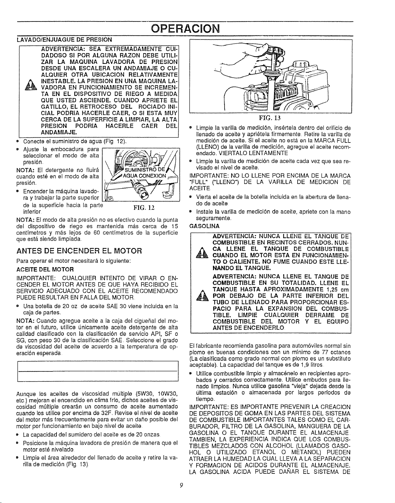
OPERACION
LAVADO/ENJUAGUE DE PRESION
ADVERTENCIA: SEA EXTREMADAMENTE CUI-
DADOSO SI POR ALGUNA RAZON DEBE UT]LI-
ZAR LA MAQUtNA LAVADORA DE PRESION
DESDE UNA ESCALERA UN ANDAMIAJE O CU-
ALQUIER OTRA UBICACiON RELATIVAMENTE
_ INESTABLE. LA PRESION EN UNA MAQUINA LA-
VADORA EN FUNClONAMIENTO SE INCREMEN-
TA EN EL DISPOSITIVO DE RIEGO A MEDIDA
QUE USTED ASCIENDE. CUANDO APRIETE EL
GATILLO, EL RETROCESO DEL ROCiADO 1NI-
ClAL PODRIA HACERLE CAER, O SI ESTA MUY
CERCA DE LA SUPERFICIE A LIMPIAR, LA ALTA
PRESION PODRIA HACERLE CAER DEL
ANDAMIAJE.
- Conecte et suministro de agua (Fig 12)..
o Ajuste la embocadura para
selecclonar el modo de alta
prest6n.
NOTA: El detergents no fluir_
cuando est_ en el modo de alta
presi6n..
- Enceader la m&quina lavado-
ray trabajar la parte superior
de la superficie hacia la parle FIG, 12
inferior
NOTA: El modo de aita presi6n no es efectivo cuando la punta
deI dispositivo de riego es mantenida m&s cerca de t5
centimetros y m_s lejos de 60 centimetros de la superficie
que est& slendo limpiada.
ANTES DE ENCENDER EL MOTOR
Para operar el motor necesitar& 1osiguiente:
ACEITE DEL MOTOR
IMPORTANTE: CUALQUIER INTENTO DE VlRAR O EN-
CENDER EL MOTOR ANTES DE QUE HAYA RECIBIDO EL
SERVICIO ADECUADO CON EL ACE1TE RECOMENDADO
PUEDE RESULTAR EN FALLA DEL MOTOR.
o Una boteila de 20 oz de aceite SAE 30 viene incluida en ta
caja de partes.
NOTA: Ouando agregue aceite a la caja del cigbe_al del mo-
tor en el futuro, utilice L]nicamente aceite detergente de alta
calidad clasificado con la clasificaci6n de servicio API, SF o
SG, con peso 30 de ta clasificaci6n SAE. Seleccione el grado
de viscosidad del aceite de acuerdo a la temperatura de op-
eraci6n esperada
AtJnque los acettes de viscosidad muitipte (5W30, 10W30,
etc) rnejoran el encendido en clima fr!o, dichos aceites de vis-
cosidad m01tiple crear&n un consumo de aceite aumentado
cuando los utilice por encima de 32F. Revise el nivet de aceite
del motor m&s frecuentemente para evitar un dafio posible del
motor por funcionamiento en bajo nivef de aceite
o La capacidad del sumidero del aceite es de 20 onzas.
o Posicione la m_.quina lavadora de presi6n de manera que el
motor est# nivelado.
• Limpie el &tea alrededor del !tenado de aceita y retire la va-
rilla de medici6n (Fig. t3)
FIG. 13
* Limpie la variita de medici6n, ins_rtela dentro dei orificio de
llenado de aceite y apri_tela firmemente. Retire la varilta de
medici6n de aceite. Si et aceite no est_ en la MARCA FULL
(LLENO) de la varilla de medici6n, agregue el aceite recom-
endado_ VlERTALO LENTAMENTE
o Limpie la varitla de medici6n de aceite cada vez que sea re-
visado el nivet de aceiteo
fMPORTANTE: NO LO LLENE POR ENCIMA DE LA MARCA
"FULL" ("LLENO") DE LA VARILLA DE MEDICIOH DE
ACEITE
o Vierta et aceite de la botella incluida en la abertura de Ilena-
do de aceite
o lnstale ta varilla de medici6n de aceite, apriete con la mano
seguramente.+
GASOLINA
ADVERTENClA: NUNCA LLENE EL TANQUE DE
COMBUSTIBLE EN REClNTOS CERRADOS, NUN-
CA LLENE EL TANQUE DE COMBUSTIBLE
@UANDO EL MOTOR ESTA EN FUNCIONAM1EN.
TO O CALIENTE. NO FUME CUANDO ESTE LLE-
NANDO EL TANQUE.
ADMERT'ENCIA: NUNCA LLENE EL TANQUE DE
COMBUSTIBLE EN SU TOTALIDAD. LLENE EL
TANQUE HASTA APROXIMADAMENTE 1,25 cm
_t POR DEBAJO DE LA PARTE INFERIOR DEL
TLIBO DE LLENADO PARA PROPORCIONAR ES-
PACIO PARA LA EXPANSION DEL COMBUS-
TIBLE. UMPIE CUALQUIER DERRAME DE
COMBUSTIBLE DEL MOTOR Y EL EQUIPO
ANTES DE ENCENDERLO
E! fabricante recomienda gasolina para autom6vi]es normal sin
plomo en buenas condiciones con un mfnimo de 77 octanos
(La clasificada como grado normal con ptomo es un substituto
aceptable)_ La capacidad del tanque es de 1,9 litros
• Utilice combustible limpio y aimac6nelo en recipientes apro-
bados y cerrados correctamente_ Utilice embudos para lle-
nado limpios, Nunca utilice gasolina "vteia" dejada desde la
ultima estaci6n o almacenada por largos periodos de
tiempo
IMPORTANTE: ES fMPORTANTE PREVENIR LA CREACiON
DE DEPOSlTOS DE GOMA EN LAS PARTES DEL SISTEMA
DE COMBUSTIBLE IMPORTANTES TALES COMO EL CAR-
BURADOR, FILTRO DE LA GASOLINA, MANGUERA DE LA
GASOLINA O EL TANQUE DURANTE EL ALMACENAJE
TAMB]EN, LA EXPERIENClA INDICA QUE LOS COMBUS-
TIBLES MEZCLADOS CON ALCOHOL (LLAMADOS GASO-
HOL O UTtLIZADO ETANOL O METANOL) PUEDEN
ATRAER LA HUMEDAD LA CUAL LLEVA A LA SEPARAClON
Y FORMACION DE ACIDOS DURANTE EL ALMACENAJE.
LA GASOLINA AC1DA PUEDE DANAR EL SlSTEMA DE
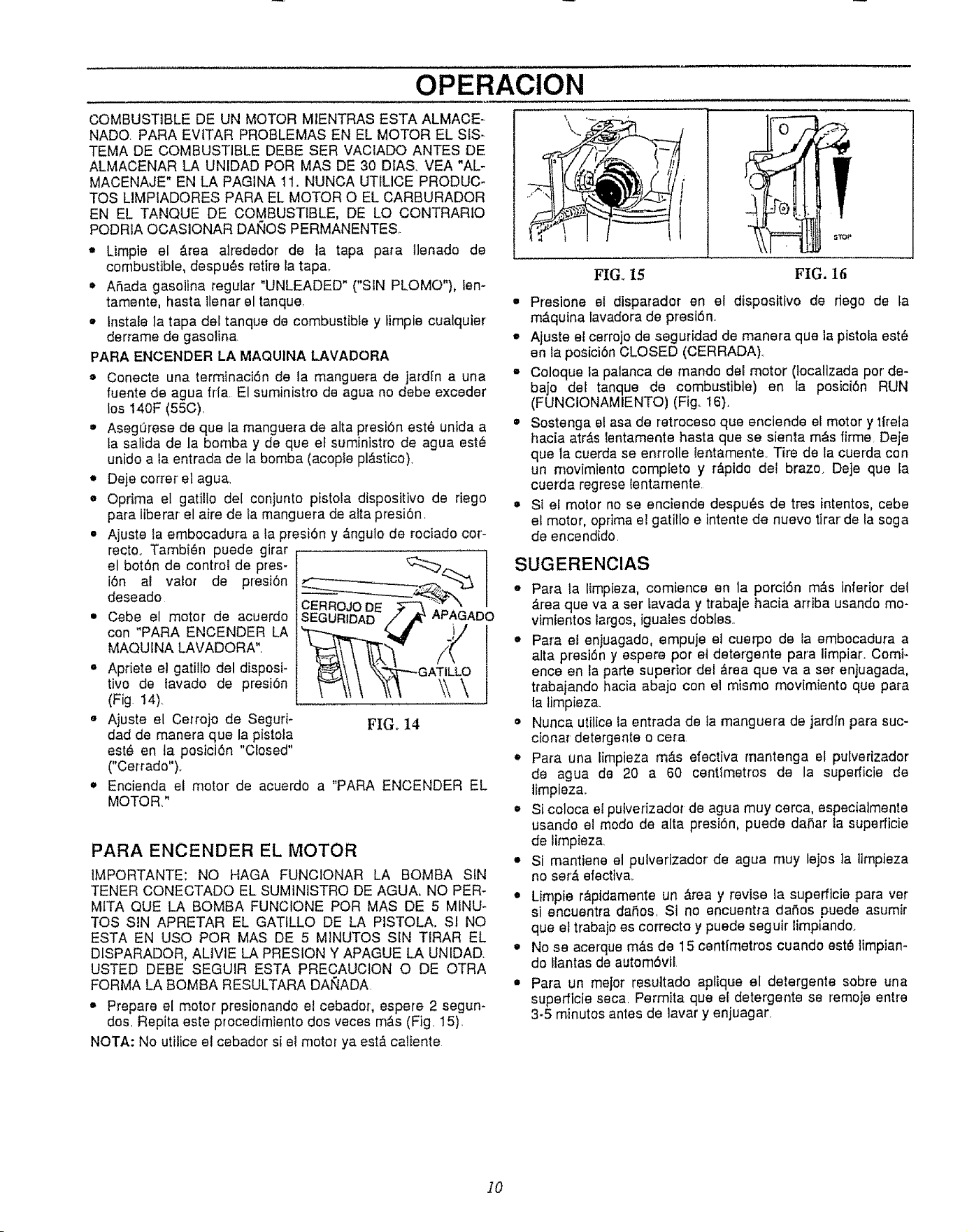
OPERACION
COMBUSTIBLE DE UN MOTOR MIENTRAS ESTA ALMACE-
NADQ PARA EVITAR PROBLEMAS EN EL MOTOR EL SIS-
TEMA DE COMBUSTIBLE DEBE SER VACIADO ANTES DE
ALMACENAR LA UNtDAD PeR MAS DE 30 DtAS, VEA "AL-
MACENAJE" EN LA PAGINA 11. NUNCA UTILICE PRODUC-
TOS LIMPIADORES PARA EL MOTOR O EL CARBURADOR
EN EL TANQUE DE COMBUSTIBLE, DE LO CONTRARIO
PODRIA OCASIONAR DANES PERMANENTES,.
• Limpie el &rea alrededor de la tape pare llenado de
combustible, despu_s retire la tap&
• ASada gasoline regular "UNLEADED" ("SIN PLOMO"), len-
tamente, haste tlenar el tanque.
• Instale la tapa del tanque de combustible y limpie cualquier
derrame de gasoline.
PARA ENCENDER LA MAQUINA LAVADORA
o Conecte una terminaci6n de la manguera de jardfn a una
fuente de agua frfa El suministro de agua no debe exceder
los 140F (55C).
• AsegSrese de que la manguera de alta presiSn est6 unlda a
fa salida de la bombay de que el suministro de agua est_
unido a ta entrada de la bomba (acople pl_stico).
• Deje cotter el ague,
o Oprima el gatiilo del conjunto pistola dispositivo de riego
para liberar el aire de la manguera de atta presi6n,
• Ajuste la embocadura a fa presiSn y #,ngulo de rociado coi-
recto. Tambi6n puede girar
el bot6n de control de pres-
iSn al valor de presi0n
deseado
Cebe el motor de acuerdo
con "PARA ENCENDER LA
MAQUINA LAVADORA".
• Apriete el gatillo del disposi-
tivo de lavado de presi6n
(Fig 14)_
• Ajuste el Cei'rojo de Seguri*
dad de manera que la pistola
est_ en ta posici6n "Closed"
CCei'rado").
• Encienda el motor de
MOTOR."
FIG. 14
acuerdo a "PARA ENCENDER EL
PARA ENCENDER EL MOTOR
IMPORTANTE: NO HAGA FUNCIONAR LA BOMBA SIN
TENER CONECTADO EL SUMINtSTRO DE AGUA. NO PER-
MITA QUE LA BOMBA FUNCtONE PeR MAS DE 5 MINU-
Tes SIN APRETAR EL GATtLLO DE LA PISTOLA. SI NO
ESTA EN use PeR MAS DE 5 MINUTES SIN TIRAR EL
DISPARADOR, ALIVIE LA PRESION Y APAGUE LA UNIDAD
USTED DEBE SEGUIR ESTA PRECAUCION O DE OTRA
FORMA LA BOMBA RESULTARA DAt_4ADA.
Prepare el motor presionando el cebador, espere 2 segun-
dos. Repita este procedimiento dos veces m&s (Fig. 15).
NOTA: No utilice el cebador si e! motor ya estfi caliente
FIG. 15
FIG. 16
o Presione et disparador en el dispositivo de dego de la
m&quina lavadora de presiSn.
• Ajusle el cerrojo de seguridad de manera que la pistola estL,
en Ia posiciSn CLOSED (CERRADA)_
• Coloque la palanca de mando del motor (Iocalizada por de-
bajo del tanque de combustible) en la pesiciSn RUN
(FUNCIONAMIENTO) (Fig.. 16}.
• Sostenga el asa de retroceso que enciende el motor y tirela
hacia atr_,s lentamente hasta que se sienta mAs firme. Deje
que la cuerda se enrrolle tentamente. Tire de la cuerda con
un movimiento completo y r&pido del brazo. Deje que la
cuerda regrese lentamente.
St el motor no se enciende despu_s de tres intentos, cebe
el motor, oprima el gatillo e intente de nuevo tirar de la soga
de encendido.
SUGERENClAS
o Para la limpieza, comience en la porciSn mils inferior del
hrea que vaa ser lavada y trabaje hacia arriba usando mo-
vimientos largos, iguales dobles..
,_ Pare el enjuagado, empuje el cuerpo de la embocadura a
alta presiSn y espere por et deteJ'gente para limpiar. Comi-
ence en la parle superior del _.rea que va a set enjuagada,
trabajando hacia abajo con el mismo movimiento que pare
la limpiez&
• Nunca utilice la entrada de ta manguera de jardln pare suc-
cionar detergente o cera
,_ Para una limpieza mg_s efeciiva mantenga el pulverizador
de ague de 20 a 60 centimetros de la supedicie de
timpieza..
o Si coloca el pulverizador de agua muy cerca, especialmente
usando et mode de alta presiSn, puede daSar ta superficie
de limpieza.
• Si mantiene el pulverizador de agua muy lejos la timpieza
no ser,'f efectiva.
• Limpie r__pidamente un &rea y revise la superficie pare vet
si encuentra da_os. Si no encuentra daSos puede asumir
que el trabajo es correcte y puede seguir limpiando..
• No se acerque m&s de 15 centlmetros cuando est_ limpian-
do ltantas de automSvtl
•Para un melor resuttado aptique el detergente sobre una
superficie seca. Permita que el detergente se remoje entre
3-5 minutos antes de lavar y enjuagar.
]0
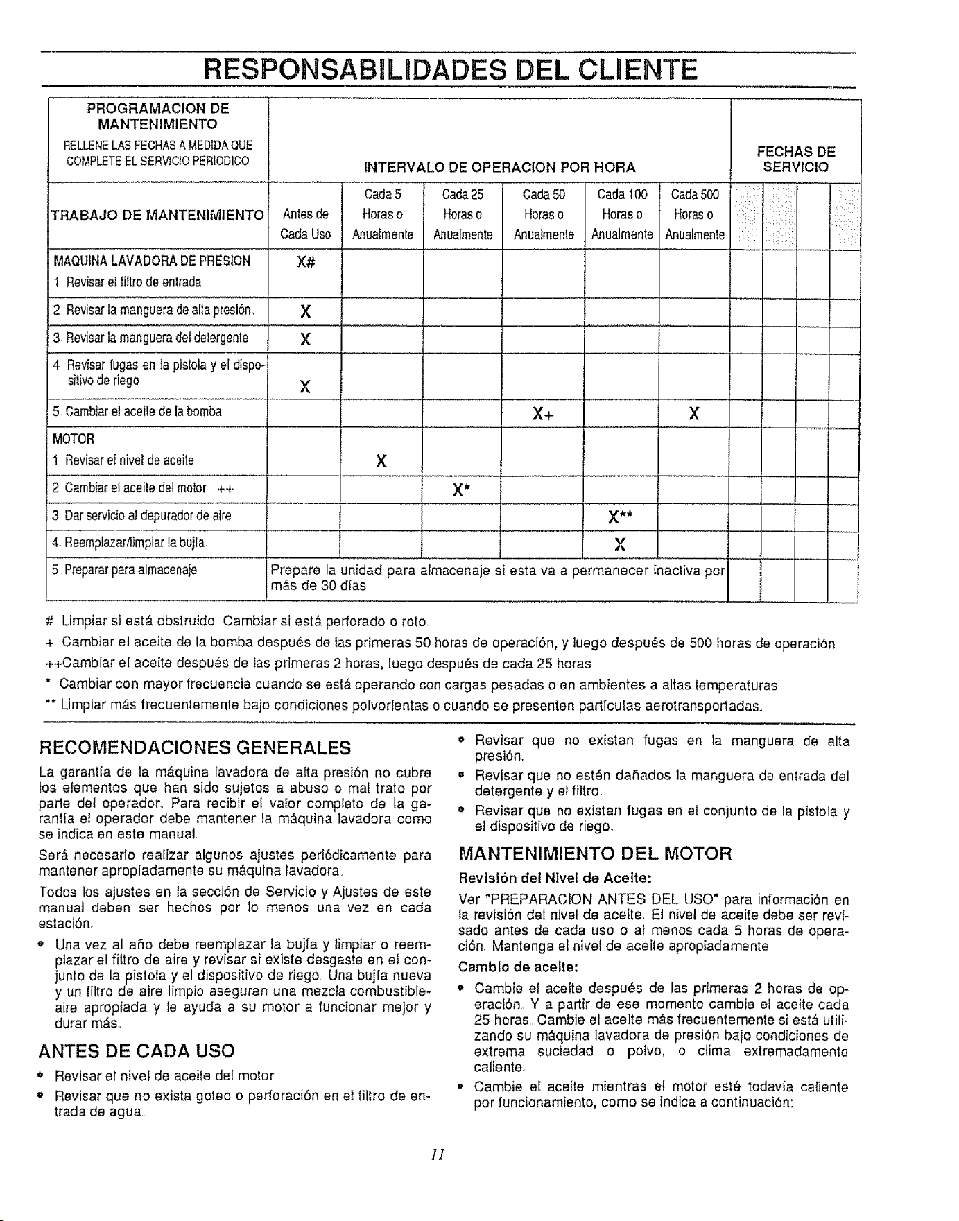
RESPONSABIL DADES DEL CLDENTE
PROGRAMAClON DE
MANTENtMIENTO
RELLENELASFECHASAMEDIDAQUE
COMPLETEELSERVICIOPERIODICO
TRABAJO DE MANTENIMIENTO
MAQUINA=LAVADORADEPREstON
1 Reviseret fiitrode en![ada
2 Revisarla mangueradealla presi6n.
3 Reviserla mangueradetdelergente
4 Revisarfugas en la pistolay el dispo-
dlivo de riego
5 Cambiare! aceitede la bomba
MOTOR
t Reviserel nivel de aceite
2 Cambiare! aceitedet motor ++
3 Dar servicioa! depuradorde aire
4. ReemplazadiimpiarIabujla,
5 Reparar paraalmacenaje
FECHAS DE
SERVICIO
...... : i
INTERVALO DE OPERACION PeR HeRA
Cada5 Cada25 Cada50 Cada100 Cada500
Antes de Horaso Horaso Horaso Horaso Horaso
CadaUse A.nuaImente A_ualmente Anualmente Anualmente Anualmente
X#
X
X
X
X+ X
X
X*
X**
X
Prepare la unidad para almacenaje si esta va a permanecer inactive per
m_,s de 30 dlas.
# Limpiar si est& obstruido Cambtar si est,_ perforado o rote.
+ Cambiar et aceite de la bomba despu6s de las primeras 50 horas de operaci6n, y tuego despu_s de 500 horas de operaci6n
++Cambiar el aceite despu#s de Ias primeras 2 bores, fuego despu_s de cada 25 horas
° Cambiar con mayor frecuencia cuando se est& operando con cargas pesadas o en ambientes a altas temperatures
** Limpiar m&s frecuentemente bajo condiciones polvorientas o cuando se presenten partfculas aerotransporladas.
RECOMENDAClONES GENERALES
La garantta de ta m,_quina lavadora de alta presi6n no cubre
fos elementos que hen side sujetos a abuse o mal trato per
parle det operador. Para recibir el valor complete de ta ga-
rantia el operador debe mantener ta m,'_quina lavadora come
se indica en este manual.
Ser& necesario reafizar algunos ajustes peri6dicamente para
mantener apropiadamente su m&quina lavadora.
Todos los ajustes en ta secci6n de Servicio y Ajustes de este
manual deben ser hechos per ]o menos una vez en cada
estaci6n.
Una vez al a_,o debe reemplazar ta bujfa y timpiar o reem-
piazar el filtro de aire y revisar si existe desgaste on el con-
junto de la pistola y el dispositivo de riego Una bujla nueva
y un filtro de aire limpio aseguran una mezcla combustible-
alre apropiada y ]e ayuda a su motor a funcionar mejor y
durar m_s..
ANTES DE CADA use
Revisar el nivet de aceite del motor.
o Revisar que no exista goteo o perforaci6n en eI filtro de en-
trada de agua
•Revisar que no existan fugas en la manguera de alta
presi6n..
• Revisar que no est_n dafiados ]a manguera de entrada del
detergente y el fittro.
_' Revisar que no existan fugas en el conjunto de la pistola y
el dispositivo de riego,
MANTENIMIENTO DEL MOTOR
Revtsi6n det Nlvel de Acette:
Ver "PREPARACION ANTES DEL use" para inlormaci6n en
la revisi6n del nivel de aceite, El nivel de aceite debe ser revi-
sado antes de cada use oal menos cada 5 horas de opera-
ci6n, Mantenga el nivel de aceite apropiadamente
Camblo de acelte:
o Cambie el aceite despu_s de las primeras 2 horas de op-
eracf6n. Y a partir de ese memento cambie et aceite cada
25 horas Gamble et aceite m&s frecuentemente si est& utili-
zando su m&qutna lavadora de presi6n baio condiciones de
extrema suciedad o polvo, o clima extremadamenle
caliente,
€, Cambie el aceite mientras e! motor est,, todavia caliente
per funcionamiento, come se indica a continuaci6n:
]]
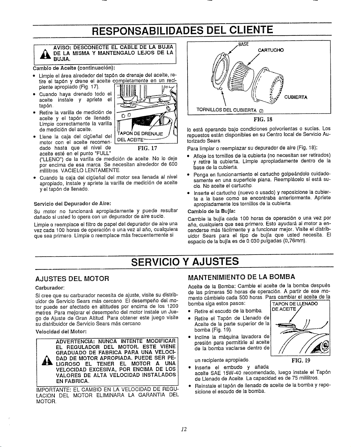
RESPONSABILIDADES DEL CLIENTE
AVISO: DESCONECTE EL CABLE DE LA BUJIA
DE LA MtSMA Y MANTENGALO LEJOS DE LA
BUJIAo
Camblo de Aceite (continuacl6n):
= Limpie el _rea alrededor del tap6n de drenaje del aceite, re-
tire el tap6n y drene el aceite en un recl-
piente apropiado (Fig. 17)_
• Cuando haya drenado todo el
aceite instale y apriete el
tap6n
• Retire la varilla de medici6n de
aceite y el tap6n de llenado.
Limpie correctamente la varitla
de medici6n del aceite..
_, Llene la caja del cig0e_al del
motor con el aceite recomen-
dado haste que el ntvei de FIG, 17
aceite est_ en el punto "FULL"
("LLENO") de la vadlla de medici6n de aceite. No 1o deje
por encima de esa marca. Se necesitan alrededor de 600
rnilJlitros. VAC1ELO LENTAMENTE.
• Cuando la caja del ciggenat del motor sea Itenada al nivel
apropiado, instale y apriete la varilla de mediciSn de aceite
y el tap6n de tlenado.
Servicio del Depurador de Aire:
Su motor no funcionar& apropiadamente y puede resultar
da5ado si usted 1oopera con un depurador de aire sucio.
Limpie o reemplace el filtro de papel del depurador de aire una
vez cada 100 horas de operacibn o una vez al aRo, cualquiera
que sea primero. Limpie o reemplace m&s frecuentemente si
\
TORNILLOS DEL CUBIERTA
FIG. 18
CUBIERTA
lo est& operando bajo condiciones polvorientas o sucias. Los
repuestos est_,n disponib[es en su Centre local de Servicio Au-
torizado Sears.
Para limpiar o reemptazar su depurador de aire (Fig. 18):
• Aftoje los tornillos de la cubierta (no necesitan ser retirados)
y retire la cublerta. Limpie apropiadamente dentro de la
base de [a cubierta.
• Ponga en funcionamiento el cartucho golpe&ndolo cuidado-
samente en una superficte plana.. Reempl&celo si est& su-
cio. No aceite el cartuchp.
• Inserte el cartucho (nuevo o usado) y reposicione la cubier-
taa la base como se encontraba anteriormente. Apdete
apropiadamente los tornilIos de la cubierta.
Camblo de la BuJ|a:
Cambie la bujIa cada 100 horas de operacibn o una vez pot
aSo, cuatquiera que sea primero, Esto ayudar& at motor a en-
cenderse m_s f_,cilmente y a funcionar mejor. Visite el distrib-
uidor Sears para el tipo de buj[a que usted necesita_ El
espacto de la bujfa es de 0.030 pu[gadas (0,76ram).
SERVlCiO Y AJUSTES
AJUSTES DEL MOTOR
Carburador:
Si cree que su carburador necesita de ajuste, visite su distdb-
uidor de Servicio Sears m_,s cercano El desempeRo del mo-
tor puede ser afectado en altitudes por encima de los 1200
metros Para mejorar el desempe_o del motor instale un Jue-
go de Ajuste de Gran Altitud. Pare obtener este juego visite
su dLstribuidor de Servicio Sears m&s cercano
Veloctdad del Motor:
ADVERTENCIA: NUNCA INTENTE MODIFtCAR
EL REGULADOR DEL MOTOR, ESTE VIENE
GRADUADO DE FABRICA PARA UNA VELOCI-
DAD DE MOTOR APROP|ADA, PUEDE SER PE-
LIGROSO EL TENER EL MOTOR A UNA
VELOCtDAD EXCESiVA, POR ENClMA DE LOS
VALORES DE ALTA VELOClDAD INSTALADOS
EN FABRICA_
IMPORTANTE: EL CAMBIO EN LA VELOCfDAD DE REGU-
LACION DEL MOTOR EL1M1NARA LA GARANTIA DEL
MOTOR.
MANTENIMIENTO DE LA BOMBA
Acette de la Bomba: Cambie el aceite de la bomba despu_s
de tas primeras 50 horas de operaci6n. A partir de ese me-
mento c&mbielo cada 500 horas. Pare cambiar el aceite de la
bomba siga estos pasos: TAPON DE LLENADO
• Retire el escudo de la bomba.. DE ACEITE/
• Retire el Tap6n de Llenado de
/
Aceite de la parte superior de la
bomba (Fig.. t9).
• Incltne la m&quina lavadora de
presi6n pare permitirle at aceite
de la bomba vactarse dentro de
un recipiente apropiado. FIGo I9
t Inserte el embudo y a_ada
aceite SAE 15W-40 recomendado, luego instale et Tap6n
de Llenado do Aceite. La capacidad es de 75 mililitros_
o Retnstale el tap6n de Ilenado de aceite de la bombay repo-
sicione el escudo de la bomba.
]2
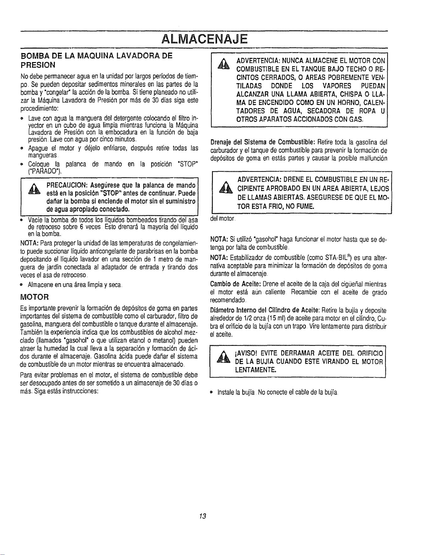
ALMACENAJE
BOMBA DE LA MAQUINA LAVADORA DE
PRESION
Nodebepermaneceragua enla unidadpot largosperioclosdetiem-
pc. Se puedendepositar sedimentosmineralesen tas partesde ta
bombay "congela¢la acci6nde labomba,Si tiene planeadono utili-
zar la M_quinaLavadorade PresiSnpor m_.sde 30 dias siga este
procedimiento:
,, Lavecon agua la manguerade! detergentecotocandoel filtro in-
yector en un cubo de agua timpiamientras funcionala M_,quina
Lavadorade Presi6ncon la embocaduraen la funci6nde baja
presi6n Lavecon aguapot cincominutos.
• Apague el motor y d_jelo enlriarse, despu_s retire todas las
mangueras.
o Coloque la palanca de mando en la posici6n "STOP"
("PARADO')..
,_ PRECAUCION:Asegureseque la palancade mando
est_ enla posici6n"STOP"antes de continuar.Puede
daf_arla bombasi enciendeelmotor sinel suministro
deagua apropiadoconectado.
Vacie la bombade todos los liquidos bombeadost_randodel asa
de retrocesosobre 6 veces Estodrenar,_la mayoriadet Ifquido
enla bomba.,
NOTA: Paraprotegerla unidaddelas ternperaturasdecongelamien-
to puedesuccionarffquidoanticongelantede parabrisasen la bomba
depositandoel liquido Iavadoren una secci6n de 1 metrode man-
guera de jardfn conectada al adaptadorde entrada y tirando dos
veceselasa deretroceso.
• Almaceneen una_rea limpiay seca.
MOTOR
Es importanteprevenirla formaci6nde dep6sitosde gomaen partes
importantesdel sistemade combustiblecomoel carburador,filtrode
gasolina,mangueradelcombustibleo tanquedurantee! almacenaje,
Tambi6nla experienciaindica quelos combustiblesde alcoholmez-
clado (lfamados"gasohol' o que utilizanetanol o metanol)pueden
atraer la humedadla cual Ilevaa ta separaci6ny formaci6nde _,ci-
dos duranteel almacenaje,,Gasotina;_cidapuededaSarel sistema
de combustibledeun motormientrasse encuentraalmacenado,
Paraevitarproblemasen el motor,et sistemade combustibledebe
ser desocupadoantesdeser sometidoa unalmacenajede30 dias o
re&s,SigaestAsinstnJcciones:
,&
ADVERTENClA:NUNCAALMACENEEL MOTORCON
COMBUSTIBLEEN EL TANQUEBAJO TECHO 0 RE-
CINTOSCERRADOS,0 AREAS POBREMENTEVEN-
TILADAS DONDE LOS VAPORES PUEDAN
ALCANZAR UNA LLAMA ABIERTA, CHISPA O LLA-
MA DE ENCEND1DOCOMOEN UN HORNO,CALEN-
TADORES DE AGUA, SECADORA DE ROPA U
OTROSAPARATOSACCIONADOSCONGA&
Drenaiedel Sistema de Combustible: Retiretodala gasolinadel
carburadory el tanquede combustibleparaprevenirla lormaci6nde
dep6sitosde goma en est_s parles y causarla posible malfuncbn
ADVERTENClA:DRENEEL COMBUSTIBLEEN UN RE-
ClPIENTEAPROBADOEN UNAREAABIERTA,LEJOS
DE LLAMAS ABIERTA& ASEGURESEDE QUE EL MO.
TOR ESTAFRIO,NO FUME.
delmotor.
NOTA:Si utiliz6"gasohot"hagafuncionarel motorhastaque se de-
tengapor faltadecombustible.
NOTA:Estabilizadorde combustible(comoSTA-BIL")es una alter-
nativaaceptablepara minimizarla formaci6nde dep6sitosde goma
duranteel almacenaje
Cambiode Aceite: Dreneel aceite de la cajadel cig0eSalmientras
et motor est_ aLTncaliente Recambie con el aceite de grado
recomendado.
Di_metroInterno del Cilindro de Aceite:Retirela bujia y deposite
alrededorde 1/2 onza(15ml) de aceiteparamotorenel citindro,Cu-
brael odficiode la bujiacon un trapo Virelentamenteparadistribuir
el aceite..
_ iAVISO! EVITE DERRAMARACEITE DEL ORIFIClO
DE LA BUJIA CUANDO ESTEVIRANDO EL MOTOR
LENTAMENTE.
o Instalela bujia Noconecteel cabledela bujia
13
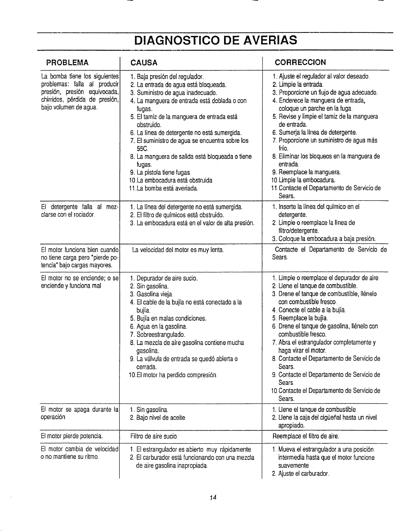
DIAGNOSTICO DE AVERIAS
PROBLEMA CORRECCION
La bomba tiene los siguientes
problemas: falla at producir
presi6n, presi6n equivocada,
chirddos, p6rdida de presi6n,
bajovolumendeagua.
CAUSA
1..Bajapresi6ndel reguladon
2. La entradade aguaest_ bloqueada.
3. Suministrodeaguainadecuadoo
4. La manguerade entradaest,.dobladao con
fugas.
5. El tamizdela manguerade entradaest,,
obstruido..
6oLa lineadedetergentenoes_ sumergida.
7. El suministrodeaguase encuentrasobrelos
55C
8. La manguerade satidaestabloqueadaotiene
El detergente falla al
clarsecon el rociador,
mez-
El motorfuncionabien cuando
notienecargapero"pierdepo-
tencia"bajocargasmayores,,
El motorno se enciende;o se
enciendey funcionamaf
fugas.
9,_La pistolatienefugas
10La embocaduraest_obstruida
tl _Labombaest_avedada.
t,, Ajusteelreguladoral valordeseado,
2, Umpiela entrada_
3. Proporcioneun ftujode aguaadecuado_,
4. Enderecela manguerade entrada,
coloqueunparcheenla fuga
5, Revisey limpieel tamiz dela manguera
deentrada,,
6. Sumerjalalineade detergente.
7. Proporcioneun suministrode aguam_s
frio,.
8. Etiminarlos bloqueosen la manguerade
entrada.
9, Reemplacela manguera.
I0 Umpielaembocadura,
1t, Contactee! Departamentode Serviciode
Sears,
1_Insertelalinea detquimicoen el
detergente_
2, Limpieo reemplacelalinea de
filtro/detergente_
3,Ooloquelaembocaduraa bajapresi6n,
Contacte el Departamentode Servicio de
Sears,.
I. La lineadeldetergenteno est_sumergida,.
2 El iiltro dequimicosest_obstsuido.
3. Laembocaduraest,_enel valor deattapresi6n,
La vefocidaddelmotores muy lenta.
1oDepuradorde airesucio_ 1
2. Singasotina. 2,
3_Gasolinavieja,, 3,
4..Elcable deta bujia noestD,conectadoa la
bujia, 4,
5,_Bujiaen malascondiciones,. 5,
6 Agua enla gasolina, 6.
7, Sobreestrangulado.
8, La mezcladeaire gasolinacontienemucha 7.
gasolina,.
9. Lav_lvulade entradasequed6abiertao 8
cerrada,
IO,.EImotortla perdidocornpresi6n.
1. Sin gasolina.
2. Bajo nivetde aceite
Filtrodeaire sucio
t, El estranguladores abierto muy rApidamente,
2 El carburadorest_funcionandocon unamezcla
de airegasolinainapropiada
Umpieo reemplaceet depuradorde aire
Uene e! tanquedecombustible,
Dreneel tanquedecombustible,II_nelo
con combustiblelresco
Conecteel cablea la bujia,
Reemplacela bujia_
Dreneel tanquedegasolina,II_.nelocon
combustiblefresco,
Abrae! estranguladorcompletamentey
hagavirar elmotor,
Contacteel Departamentode Serviciode
Sears.
£ Contacteet Departamentode Serviciode
Sears
lOContacte elDepartamentode Serviciode
Sears.
Et motor se apaga durante la 1_Uene el tanquede combustible
operaciOn & Uene la cajadelcigOeSalhastaunnivel
apropiado.
Reemplaceel filtrodeaire.Elmotorpierdepotencia,,
El motor cambia de velocidad
o no mantienesuritmo
1, Muevaelestranguladora unaposici6n
intermediahastaqueel motorfuncione
suavemente
2. Aiusteet carburadon
14
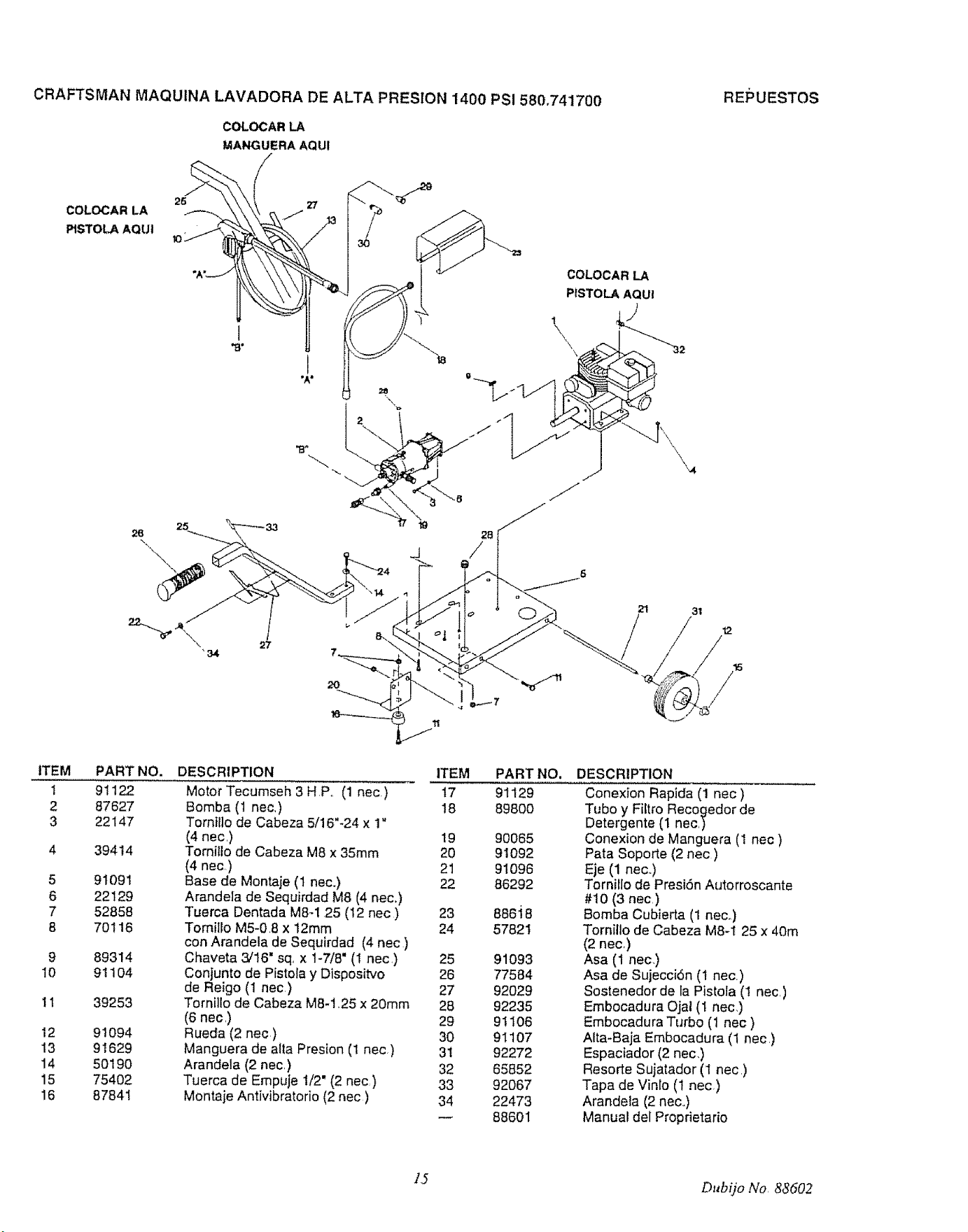
CRAFTSMAN MAQUINA LAVADORA DE ALTA PRESION 1400 PSI 580.741700
COLOCAR LA
MANGUERA AQUI
RE_SUESTOS
COLOCAR LA 26 _ 30?
PISTOLA AQU!
\
"34
COLOCAR LA
PtSTOLAAQUI
\
21 31
/°
'L. /ii
ITEM
i
2
3
5
6
7
8
9
10
1t
I2
t3
14
15
16
PART NO.
91122
87627
22147
39414
91091
22129
52858
70116
89314
91104
39253
91094
91629
50190
75402
87841
DESCRIPTION ITEM
Motor Tecumseh 3 H .P.. (1 nec) 17
Bomba (1 nec.) 18
Torn}llo de Cabeza 5/16"-24 x 1"
(4 nec.) 19 90065
Tornillo de Cabeza M8 x 35ram 20 91092
(4 nec) 21 91096
Base de Montaje (1 nee.) 22 86292
Arandela de Sequirdad M8 (4 nec.)
Tuerca Dentada M8-1 25 (t2 nec) 23 886i8
TomiIIo M5-0.8 x 12mm 24 57821
con Arandela de Sequirdad (4 nec )
Chaveta 3/16" sq, x 1-7/8" (1 nec.) 25 91093
Conjunto de PistoIa y Dispositvo 26 77584
de Reigo (1 nec.) 27 92029
Tomillo de Cabeza M8-1.25 x 20ram 28 92235
(6 nec.) 29 91106
Rueda (2 nec.) 30 9I 107
Manguera de alia Presion (1 nec) 31 92272
Arandela (2 nec) 32 65852
Tuerca de Empuje t/2" (2 nec) 33 92067
Montaje Antivibratorio (2 nec ) 34 22473
88601
PART NO,
91129
89800
DESCRIPTION
Conexion Rapida (1 nec )
Tubo y Fiftro Recogedor de
Detergente (I nec.)
Conexion de Manguera (1 nec )
Pata Soporte (2 nec.)
Eje (1 neo.)
Tornillo de Presi6n Autorroscante
#10 (3 nec.)
Bomba Cubierta (1 neco)
Tomillo de Cabeza M8-1 25 x 40m
(2 nec.)
Asa (1 nec.)
Asa de Sujecci6n (1 nec)
Sostenedor de la Pistola (1 nec.)
Embocadura Ojal (1 nec.)
Embocadura Turbo (1 nec )
Alta-Baja Embocadura (1 nec)
Espaciador (2 nec.)
Resorte Sujatador (1 nec.)
Tapa de Vinlo (1 nec)
Arandela (2 nec..)
Manual del Proprietario
1,5 Dubqo No, 88602
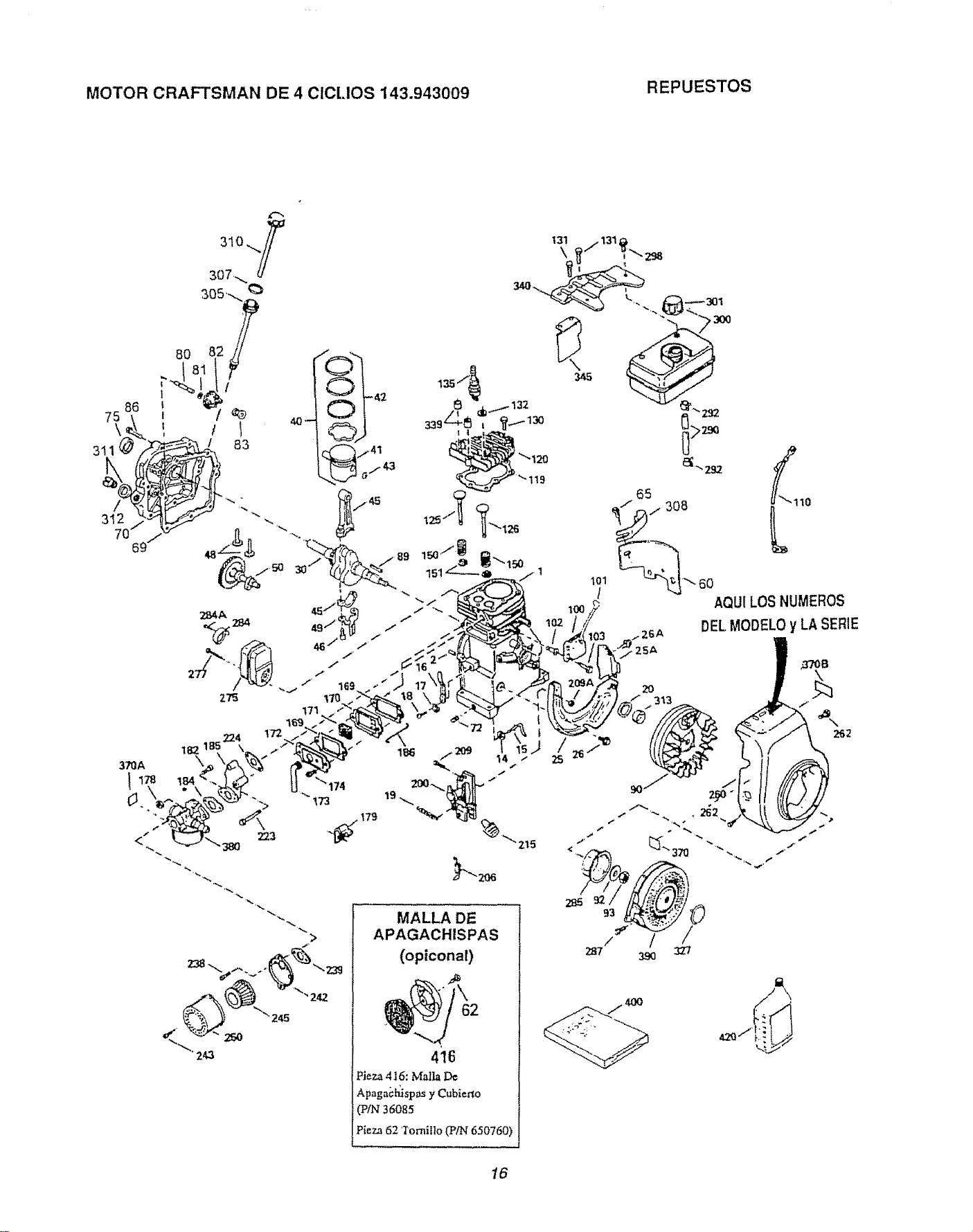
MOTOR CRAFTSMAN DE 4 ¢IClJOS 143.943009 REPUESTOS
75
\
3ti
182
!84
223
>
MALLA DE
APAGACHISPAS
(opiconal)
Pieza 416: Mall_ De
Apaga_:_sp_ y Cublerto
(PIN36085
Pieza 62 Iornil]o (P/N 650760)
40O
16
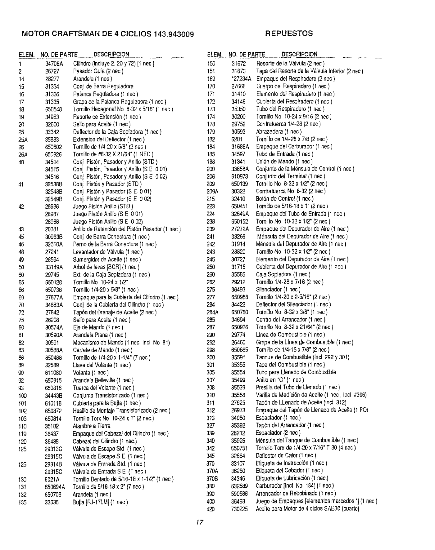
MOTOR CRAFTSMAN DE 4 CICLIOS 143.943009 REPUESTOS
ELEM. NO, DEPAnE
1 34708A
2 26727
14 26277
15 31334
16 31336
17 31335
t8 650548
19 3495.3
20 32600
25 33342
25A 35883
26 650802
26A 650926
40 34514
34515
34516
41 325388,
32548B
32549B
42 28986
28987
28988
43 20381
45 30963B
46 326t0A
48 27241
49 28594
50 33t49A
60 29745
65 650128
66 650738
69 27677A
70 34683A
72 27642
75 26208
80 30574A
81 3059OA
82 30591
83 30588A
86 650488
89 32589
90 611080
92 650815
93 650816
t00 34443B
I0I 610118
102 65O872
t03 650814
110 35182
1!9 36437
120 36438
!25 293t3C
29315C
126 29314B
29315C
130 6021A
13t 650694A
!32 650708
135 33636
DESCRtPCION
Cilindro(incfuy'e2, 20 y72) [1 nec]
PasadcrGala (2nec)
Atandela(1nec)
Conj de BarraReguladota
PaiancaReguladcra(1 nec)
Gr@ade la PalancaReguladora(1 nec)
Tornil[oHexagonalNo 8-32x 5/16"(1 nec)
ReserVede Extensi6n(I nec }
SelfopareAceile (1 nec)
Defleclorde la CajaSopladora(1 nec)
ExtensidndetDeflector(1nec )
Tomillcde 1/4-20x 5.,'8"(2nec )
Tornillode #8_32X 2t/64" (1NEC )
Conj Pist6n,PasaderyAnilto(STD)
Conj Pis_6n,Pasadory Anillo(S E 0 01)
Conj Pist6n,Pasadcry Anilto(SE 0 02)
Conj Pist6ny Pasador(STD)
Conj.Pisl6n y Pasador(S E 0 0I)
Conj PistSny Pasader(S E 0 02)
JuegoPistSnAnillo(STD }
Juegc Pisl6nAnilto(S E 0 01)
Juegc Pist6nAniUo(S E 0 02)
Anillode Retenci6ndel Pisl6n Pasadcr(1 nec)
Conj.deBarraConecto_a(I nec )
Pernode laBarra Conectora(! nec)
Levantadcrde V_vula (1 nec)
Sumergidarde Aceite(1 nec)
ArboldeIevas[BCR](I nec)
Ext de _aCajaScpladora(I nec)
TorniHoNc 10.24x I,'2"
Tornillo1/4-20x 5/8"(1 nec)
Empaquepareta Cubtertadel CiIindro(1..nee)
Coaj de laCubiedadel Cilindro(1nec)
Ta.p6ndel OrenajedeAceile (2 nec)
SeflcpareAceile (1 nec)
Ejede Mandc(I nec)
ArandelaPlana(I nec)
MecanismodeMando(I nec Incl No 8t)
CarreledeMando(! nec)
Torniltode 114-20x 1-t/4" (7 nec)
Uave delVolante(1nec )
Vclanle(I nec)
/_'andelaBellevilie(! nec)
TuercadetVolante(1 nec )
ConjuntoTransislorizade(1 nec)
Cubiertaparela Bujla (1 nec)
Husi!lode MonlajeTransistorizado(2 nec)
Tomiilo Torx No 10-24x 1"(2 nee)
Alambrea Tierra
Empaquedel CabezaJdel Ctlindro(1 nec)
Cabezaidel Ctlindro(1 nac)
V&lvuladeEscapeStd (1 nec)
V&_vulade EscapeS E (t nec )
V_lvutade EnlradaStd (1 nec)
V&lvuladeEntradaSE (I nec)
Tomlllo Denladode 5/!6-18 x 1-1f2"(1nec)
Tomiilode 5116-t8x 2" (7 nec)
A.randeia(I nec.}
Bujla [RJq 7LM](1 nec)
ELEM.
!50
15t
169
I70
17I
I72
173
174
I78
179
I82
184
185
188
2O0
206
209
209A
215
223
224
238
239
241
242
243
245
250
260
262
275
277
284
264A
285
287
290
292
298
300
301
305
307
308
310
3tl
3t2
313
327
339
340
342
345
370
370A
3708
38O
39O
4OO
420
NO.DE PARTE
31672
31673
'27234A
27666
31410
34146
3535O
30200
29752
30593
6201
31688A
34597
31341
33858A
610973
650139
30322
32410
650451
32649A
650152
27272A
33266
31914
28820
30727
31715
35585
29212
36493
650988
34422
650760
34694
650926
29774
2846O
650665
35591
35355
35554
35499
35539
35556
27625
26973
34080
35392
26212
35926
650751
32664
33107
36260
34346
632589
590688
36493
730225
DESCRIPCION
Rosettede la V_lvula(2 nec)
Tapedel Resortedela VtllvutaInferior(2 nec)
EmpaquedelRespiradero(2 nec)
CuerpodelRespiradero(1nec )
Eiementcdel Respiradere(1 nec)
Cubiertadel Respiradero(1nec )
Tubadel Respiradero(1 nec)
Tcmit!oNo IO-24x9/16 (2nec )
Conlratuerca114-28(2 nec)
Abrazadera(! nec)
Tornillode 1/4-28x 7/8(2 nec)
Empaquede! Carbvrador(1 nec)
Tubade Entrada(1 nec )
Uni6ndeMando (1 nec)
C,,onjuntode la M_nsulade Control(1 nec)
ConjuntodetTerminal(1 nec)
TomiltoNo 8_32x 1/2"(2nec }
CcntratuercaNo 8-32(2 nec)
Bot6nde Cant{el(1nec)
Tornitlode5/16-18x t" (2 nec)
Empaquedel Tuba de Entrada(1 nec)
Tcrnil]oNc t0-32 x 1/2" (2nec )
EmpaquedelDepuradorde Aire(1 nec)
M6nsulade! OepuradordeAire (I nec)
M_nsuladel DepuradordeAire (t nec )
TornilloNo 10.32x 1/2" (2nec)
Elementodel Depuradorde Aire(1 nec)
CubiertadelDepuradorde Aire(1nec )
Caja Soptadora(1 nec)
Torni!Io1/4-28x 7/16 (2 nec)
Silenciador(1 nec)
Tornillo1/4-20× 2-5/I6" (2nec)
Deflectordei SiIenoiador(1 nec)
Tomillo No 8.32 x 3/8"(1 nec)
Centredel Arrancador(1 nec)
To_'ni]loNo_842 x 21/64"(2nec)
Llneade Combustible(t nec)
Grapede la Llnea de Combustible(1 nec )
Tornitlode 1/4-t5 x 7/8" (2nec )
Tanquede Combustible(Incl 292 y301)
Tapedel Combustible(1 nec}
Tubapara Llenadode Combustble
t,.n.illoen "O" (1 nec)
Presitladel Tubade Llenado(1nec )
Va/itlade MediciTnde Aceite(I nec, Inc{ #306)
Tap6ndeLLenadc de Aceite(Inct312)
EmpaquedelTap6nde Llenadode Aceite(! PQ)
Especiador(t nec)
Tap6ndel Arrancador(! nec)
Espaciador(2 nec )
M_nsuladel Tanquede Combustible(! nec)
TornilloTcrx de I/4-20 x7/16" T-30(4 nec)
Deflectorde Calor(1 nec)
Eliquelade lnslrucci6n(1 nec )
Etiquetadel Cebador(1 nec)
Etiquetade Lubricacbn(I nec.)
Carburadar[lnoi No 1841(1 nec)
Arrancadorde Rebobinado(I nec)
Juegode Empaques[elementcsmarcades'] (1 nec)
Aceitepare Motorde 4 cities SAE30(cuar_o}
17
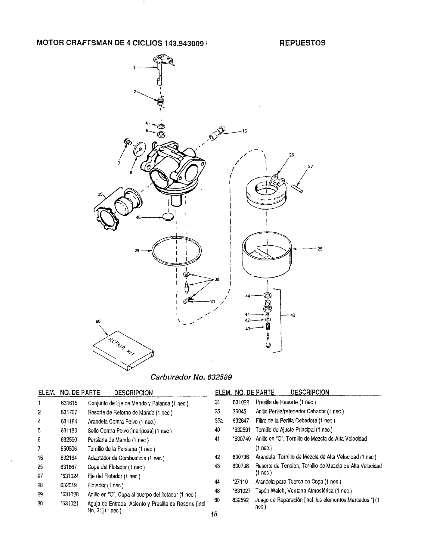
MOTOR CRAF-I'SMAN DE 4 CICLIOS 143.943009 t
REPUESTOS
ELEM.
t
2
4
5
6
7
I6
25
27
28
29
30
j
t I
6o
\
\
1 1
1 /
! /
1 t"
I 1"
\ i"
- .SJ
Carburador No. 632589
I
I
I
4!--@
42...,--_,_L_D
28
27
NO, DEPARTE
631615
631767
631184
631183
632590
650506
632164
631867
"63!024
632019
"631028
*631021
DESCRIPClON
Conjunlode Ejede Mandoy Palanca(t nec)
Resottede RetomodeMando(I nec )
ArandelaContraPotvo(1nec,)
Sello ConlraPolvo[mariposa](1nec )
Persianade Mando(1nec)
Tornillodela Persiana(t nec)
AdaptadordeCombustible(I nec)
Copadet Flolador(1nec )
Ejedel Flolador(1nec)
Ftotador(1nec)
Anilloen "0"oCopaa! cuerpodel llotador(1 nec )
Agujade Entrada,Asienloy Presillade Resorte[incl
No 31](! nec)
ELEM, NO. DE PARTE
3I 631022
35 36045
35a 632647
40 "632591
41 "630740
t8
42 630738
43 630738
44 "2711O
48 '631027
60 632592
DESCRIPClON
Presillade Resorte(1nec )
AnilioPeriiiairetenedorCebader(1 nec,)
Filtrode la PerillaCebadora(I nec)
Torniltode AjustePrincipal(! nec)
Anilloen "0", Terni!lo doMezcladeAlta Ve!ocidad
(1nec)
/_andela,Tomillo de Mezctade Alta Velocidad(1nec}
Resortedo Tensi6n,TornillodeMezclade AltaVelocidad
(t nec)
Arandelapara Tuerca deCopa(I nec,)
Tap6nWelch,VentanaAtmosf_rica(1 nec)
Juegode Reparaci6nlind loselementosMarcados"](1
rlec ,)
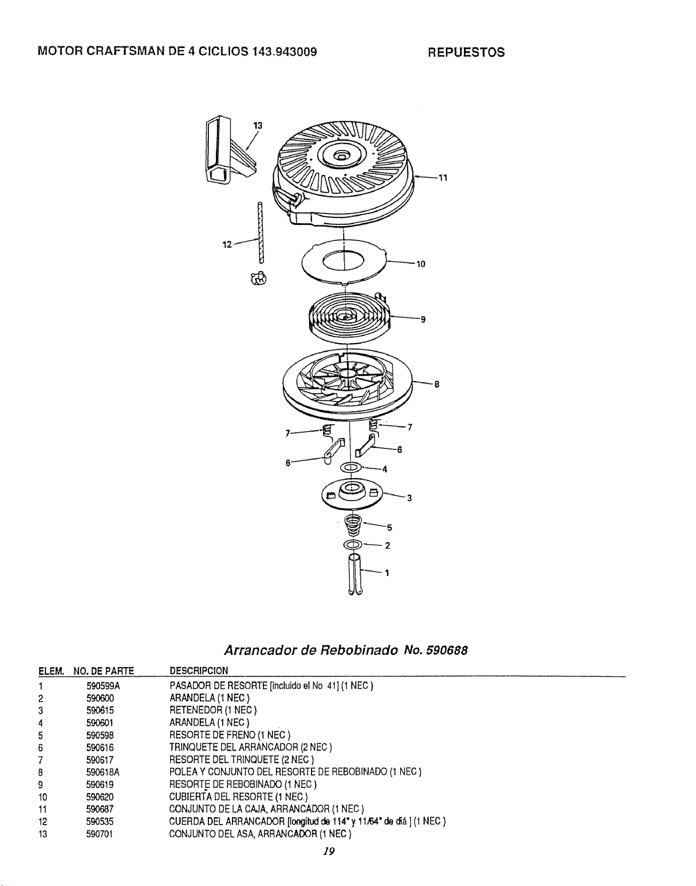
MOTOR CRAFTSMAN DE 4 ClCLIOS 143,943009 REPUESTOS
ELEM.
1
2
3
4
5
6
7
8
9
10
11
12
13
NO. DE PARTE
590599A
59O6OO
59O615
590601
590598
59O616
590617
590618A
5_19
59O620
59O687
590535
590701
Arrancador de Rebobinado No. 590688
DESCRIPCION
PASADORDERESORTE[inclutdoe] No 41] (1NEC)
ARN'.JDELA(1 NEC)
RETENEDOR(1NEC)
ARANDELA(1 NEC)
RESORTEDE FRENO(1 NEc)
TRINQUETEDELARRANCADOR(2 NEC)
RESORTEDELTRINQUETE(2NEC)
POLEAY CONJUNTODEERESORTEDEREBOBINADO(t NEC)
RESORTEDEREBOBINADO(1 NEC)
CUBtERTADEERESORTE(t NEC,)
CONJUNTO DELA CAJA,ARRANCADOR(i NEC )
CUERDADELARRANCADOR[tongitudde !14"y 1I/6,4"ded{_] (1NEC)
CONJUNTODELASA,ARRANCADOR(t NEC)
/9
MANUAL DEL
USARIO
MODELO NO.
580.741700
SI NECESITA
REPARACIONES
SERVICIO O
PIEZAS
CON REPARACIONES
SERVICIO, LLAME EL
TELEFONO GRATUITO
1-800-4°REPAIR
(1-800-473-7247)
CON INFORMAClON DE
REPARACIONES DE PIEZAS
Y PEDIDOS, LLAME EL
TELEFONO GRATUITO
1-800-FON-PART
(1-800-366-7278)
CRRFTSMRN
MAQUINA LAVADORA DE ALTA
PRESION
14ooPSi
3 CABALLOS DE FUERZA
Cada M_quina Lavadora de Alta Presi6n posee su propio n0mero de
modelo. Cada motor posee su propio nOmero de modelo.
El n0mero de modelo de su m_quina lavadora de presi6n ser'& encontrado
en una etiqueta adherida a la unidado
El nt3mero de modeKo del motor ser_. encontrado en la Caja del Soplador
del motor adyacente a la bujiao
Todas las partes enlistadas aqui pueden set ordenadas a trav_s de los
Centros de Servicio de Sears, Roebuck and Co. y la mayoria de las
Tiendas de Venta al Detalo
APORTE SIEMPRE LA SIGUIENTE INFORMACION CUANDO
ESTE ORDENANDO REPUESTOS:
• PRODUCTO-- MAQUINA LAVADORA DE ALTA
PRESION
• NUMERO DE MODELO--, 580.747100
• NO. DE PARTE DEL MOTOR -- 143.943009
• NUMERO DE LA PARTE
• DESCRIPCION DE LA PARTE
A su mercancia de Sears se le ha a5adid valor' debido a que Sears tiene
unidades de servicio en toda Banaci6n equipades con ttfichnicos en-
trenados pot Sears._t6cnicos profesionales entranados especificarnente
en los productos de Seals, poseyendo las partes, la herramientas y los
equipos neceesarieos para asegurale que vamos a satisfacer nuestro
comprosio con usted, le damos servicio a Io que vendemos.
SEARS, ROEBUCK and CO., Hoffman Estates, IL 60179 U.S.A.
Part No 88601 Revision 0 (1117194) Printed in U S A,.
