

AXISA9910I/ORelayExpansionModule
TableofContents
Installation................................................3
Congureyourdevice........................................4
Addanencryptionkey...........................................4
Addanexpansionmodule.........................................4
CongureanI/Oport............................................4
Congurearelay................................................5
Thewebinterface...........................................6
Specications..............................................7
Productoverview................................................7
LEDindicators..................................................7
Buttons.......................................................8
Connectors....................................................8
Troubleshooting............................................14
Resettofactorydefaultsettings...................................14
Checkthecurrentdevicesoftwareversion...........................14
Upgradethedevicesoftware......................................14
Technicalissues,clues,andsolutions................................14
TroubleshootstatusLEDs.........................................15
Contactsupport.................................................15
2

AXISA9910I/ORelayExpansionModule
Installation
Installation
Towatchthisvideo,gotothewebversionofthisdocument.
help.axis.com/?&piaId=92442§ion=install
3

AXISA9910I/ORelayExpansionModule
Configureyourdevice
Configureyourdevice
Note
TheexpansionmodulecanonlybeusedtogetherwithAXISA9210NetworkI/ORelayModule.Toconguretheexpansion
module,gotothewebinterfaceofyourAXISA9210.Formoreinformation,seetheusermanual.
Addanencryptionkey
YouneedtosetupanencryptionkeybeforeyouaddanyAXISA9910.Theencryptionkeyensurestheencryptedcommunication
betweenAXISA9210andAXISA9910.
Note
•Theencryptionkeyisnotvisibleinthesystem.Ifyougeneratethekey,youneedtoexportandsaveitinasafeplace
beforeyoucontinue.
•Toresettheencryptionkey,youneedtoresetthedevicetofactorydefault.SeeResettofactorydefaultsettingsonpage14.
1.GotothedevicewebinterfaceofyourAXISA9210.
2.GotoDevice>I/Osandrelays>AXISA9910andclick
Addencryptionkey.
3.Setuptheencryptionkeyinoneofthefollowingways:
-UnderEncryptionkey,enterthekey.
-ClickGeneratekeytogeneratethekeyandthenclickExportkeytosavethekey.
4.ClickOK.
Addanexpansionmodule
Note
Eachexpansionmodulehasauniqueaddress,whichcanbeconguredthroughtheDIPswitchconnector.SeeDIPswitch
connectoronpage10.
1.ConnectanexpansionmoduletoyourAXISA9210.
2.GotothedevicewebinterfaceofyourAXISA9210.
3.Setupanencryptionkey.SeeAddanencryptionkeyonpage4.
4.GotoDevice>I/Osandrelays>AXISA9910,andclick
AXISA9910.
5.Enterthenameandselecttheaddressfortheexpansionmodule.
6.ClickSave.
CongureanI/Oport
1.InthewebinterfaceofyourAXISA9210,gotoDevice>I/Osandrelays>AXISA9910.
2.Clicktheexpansionmoduleyouwanttocongure.
3.UnderI/Os,click
toexpandtheI/Oportsettings.
4

AXISA9910I/ORelayExpansionModule
Configureyourdevice
4.Renametheport.
5.Congurethenormalstate.Click
foropencircuit,orforclosedcircuit.
6.ToconguretheI/Oportasinput:
6.1UnderDirection,click.
6.2Tomonitortheinputstate,turnonSupervised.SeeSupervisedinputsonpage12.
Note
InAPIs,thesupervisedI/Oportsworkdifferentlyfromthesupervisedinputports.Formoreinformation,goto
theVAPIX®Library.
7.ToconguretheI/Oportasoutput:
7.1UnderDirection,click
.
7.2ToviewtheURLstoactivateanddeactivateconnecteddevices,gotoToggleportURL.
Congurearelay
1.InthewebinterfaceofyourAXISA9210,gotoDevice>I/Osandrelays>AXISA9910.
2.Clicktheexpansionmoduleyouwanttocongure.
3.UnderRelays,click
toexpandtherelaysettings.
4.TurnonRelay.
5.Renametherelay.
6.ToviewtheURLstoactivateanddeactivatetherelay,gotoToggleportURL.
5

AXISA9910I/ORelayExpansionModule
Thewebinterface
Thewebinterface
TheexpansionmodulecanonlybeusedtogetherwithAXISA9210NetworkI/ORelayModule.Toreachthedevice’swebinterface,go
tothewebinterfaceofyourAXISA9210.
Addencryptionkey:Clicktosetupanencryptionkeytoensureencryptedcommunication.
AddAXISA9910:Clicktoaddanexpansionmodule.
•Name:Editthetexttorenametheexpansionmodule.
•Address:Showstheaddressthattheexpansionmoduleisconnectedto.
•Devicesoftwareversion:Showsthesoftwareversionoftheexpansionmodule.
•Upgradedevicesoftware:Clicktoupgradethedevicesoftwareoftheexpansionmodule.
I/Os
I/O:Turnontoactivateconnecteddeviceswhentheportisconguredasoutput.
•Name:Editthetexttorenametheport.
•Direction:Click
ortocongureitasinputoroutput.
•Normalstate:Click
foropencircuit,andforclosedcircuit.
•Supervised:Turnontomakeitpossibletodetectandtriggeractionsifsomeonetamperswiththeconnectionto
digitalI/Odevices.Inadditiontodetectingifaninputisopenorclosed,youcanalsodetectifsomeonehastampered
withit(thatis,cutorshorted).Tosupervisetheconnectionrequiresadditionalhardware(end-of-lineresistors)in
theexternalI/Oloop.Itappearsonlywhentheportisconguredasinput.
-Touseparallelrstconnection,selectParallelrstconnectionwitha22KΩparallelresistoranda4.7
KΩserialresistor.
-Touseserialrstconnection,selectSerialrstconnectionandselectaresistorvaluefromtheResistor
valuesdrop-downlist.
•ToggleportURL:ShowstheURLstoactivateanddeactivateconnecteddevicesthroughtheVAPIX®Application
ProgrammingInterface.Itappearsonlywhentheportisconguredasoutput.
Relays
•Relay:Turnonorofftherelay.
•Name:Editthetexttorenametherelay.
•Direction:Indicatesthatitisanoutputrelay.
•ToggleportURL:ShowstheURLstoactivateanddeactivatetherelaythroughtheVAPIX®ApplicationProgramming
Interface.
6
AXISA9910I/ORelayExpansionModule
Specifications
Specifications
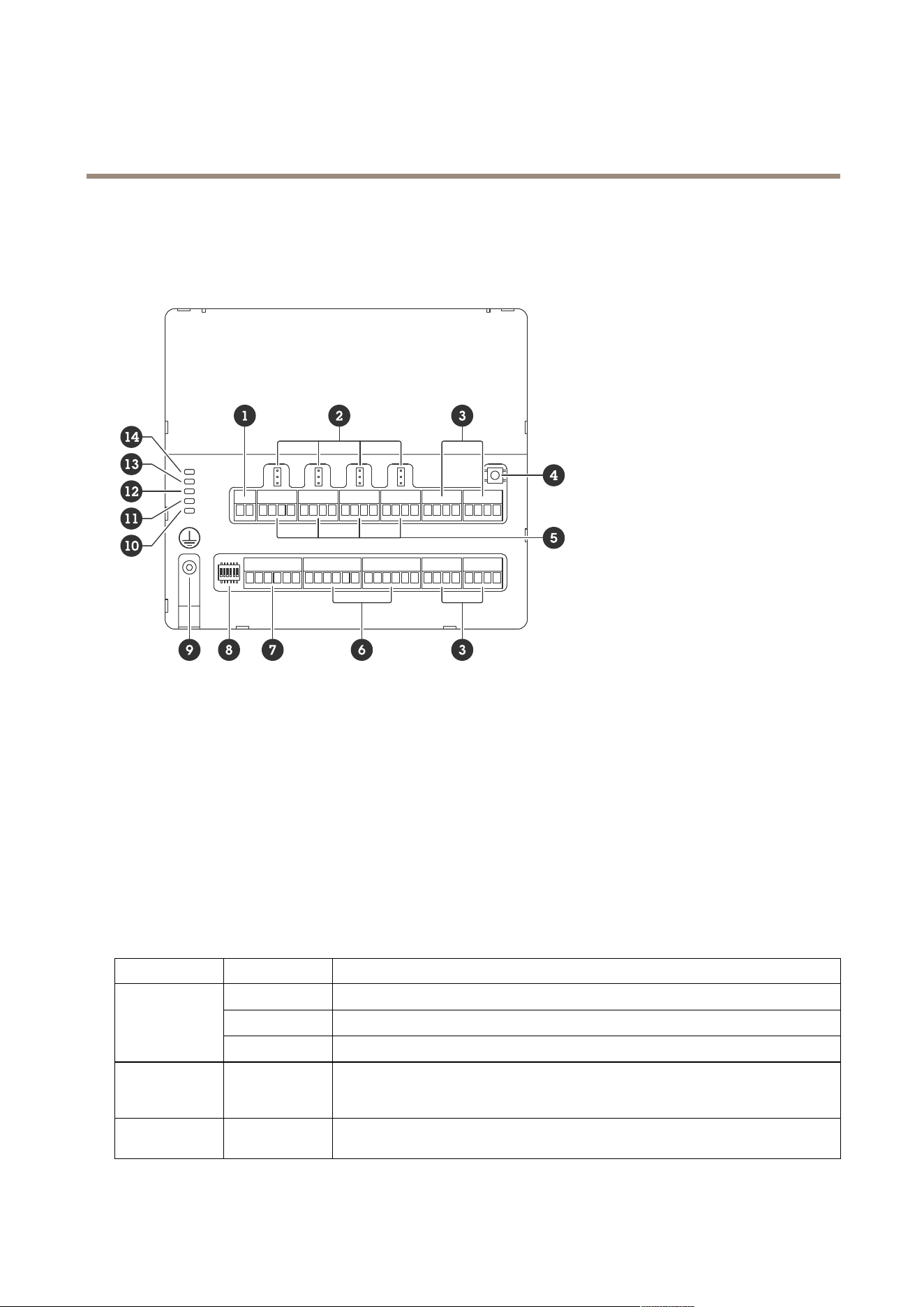
Productoverview
1
Powerconnector
2
Relayjumper
3
RS485connector
4
Controlbutton
5
Relayconnector
6
Auxiliaryconnector
7
Expansionconnector
8
DIPswitch
9
Groundingposition
10
RelaystatusLED
11
RS485statusLED
12
PowerstatusLED
13
ExpansionstatusLED
14
StatusLED
LEDindicators
LED
Color
Indication
Green
Blinks(onfor1second,offfor1second)whenofine.
Green
Blinks(blinkfor2times,offfor2seconds)whenonlinewithencryptedcommunication.
Status
(STAT)
Red
Blinksgreen/redduringdevicesoftwareupgrade.
Expansion
network
(EXPNET)
Green
Blinkswhentransmittingdata.
Power
(PWR)
Green
Normaloperation.
7
AXISA9910I/ORelayExpansionModule
Specifications
RS485over
current
(RS485OC)
Red
OvercurrentorundervoltagefaultonanyRS485port.
Relayover
current
(RelayOC)
Red
Overcurrentorundervoltagefaultonanyrelayport.
FormorestatusLEDindicators,seeTroubleshootstatusLEDsonpage15.
Buttons
Controlbutton
Thecontrolbuttonisusedfor:
•Resettingtheproducttofactorydefaultsettings.SeeResettofactorydefaultsettingsonpage14.
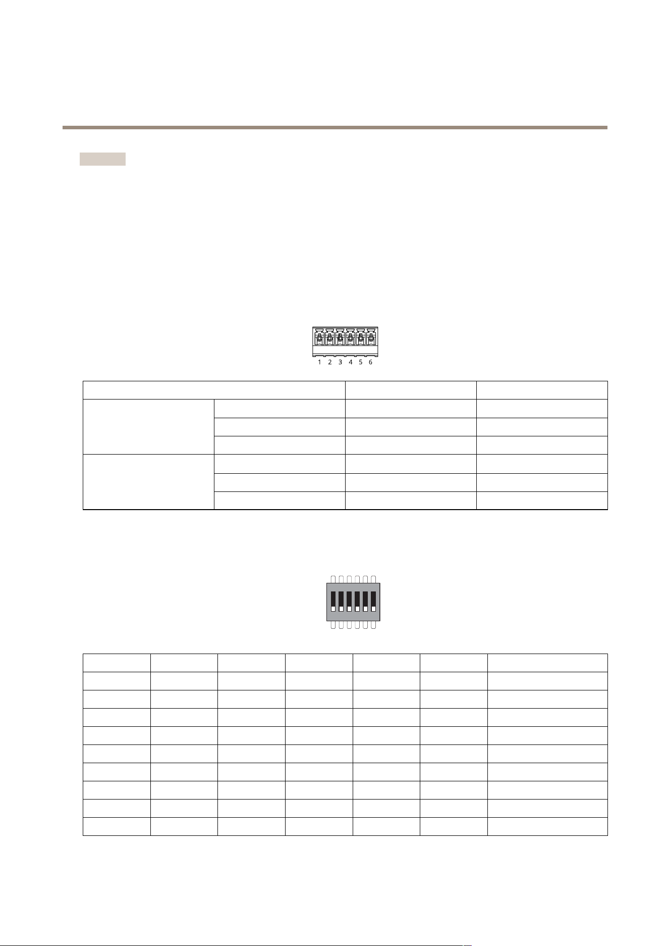
Connectors
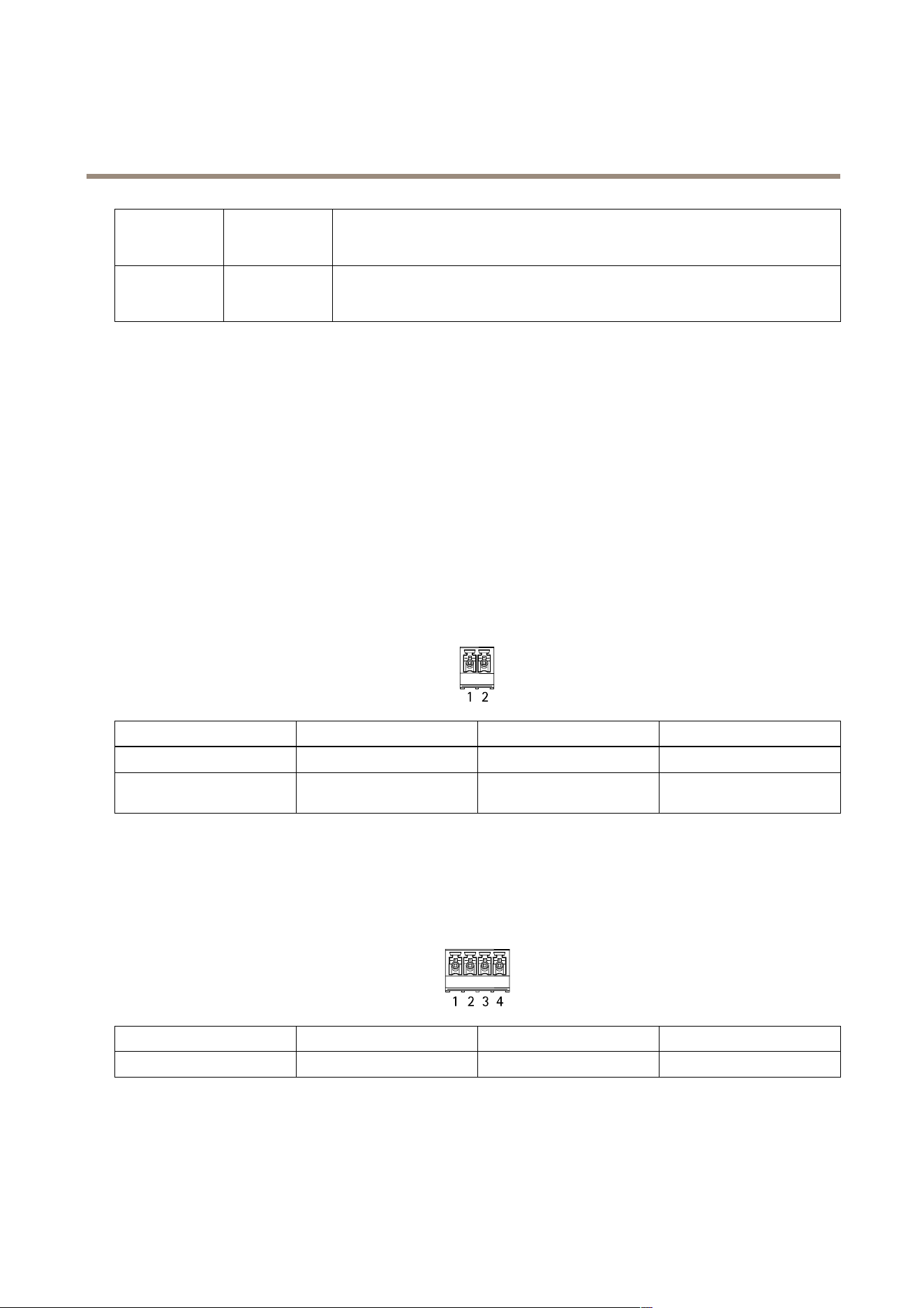
Powerconnector
2-pinterminalblockforDCpowerinput.UseaSafetyExtraLowVoltage(SELV)compliantlimitedpowersource(LPS)witheither
aratedoutputpowerlimitedto≤100Woraratedoutputcurrentlimitedto≤5A.
FunctionPinNotes
Specications
DCground(GND)
1
0VDC
DCinput
(12–24V)
2
Thispincanonlybeusedas
powerin.
12–24VDC,max90W
UL:DCpowertobesuppliedbyaUL603listedpowersupply,dependingonapplication,withappropriateratings.
Relayconnector
Four4-pinterminalblocksforformCrelaysthatcanbeused,forexample,tocontrolalockoraninterfacetoagate.Ifusedwithan
inductiveload,forexamplealock,connectadiodeinparallelwiththeloadtoprotectagainstvoltagetransients.
FunctionPinNotes
Specications
DCground(GND)
1
0VDC
8
AXISA9910I/ORelayExpansionModule
Specifications
NO
2
Normallyopen.
Forconnectingrelaydevices.
Connectafail-securelock
betweenNOandDCground.
Thethreerelaypinsare
galvanicallyseparatedfrom
therestofthecircuitryifthe
jumpersarenotused.
COM
3
Common
Thethreerelaypinsare
galvanicallyseparatedfrom
therestofthecircuitryifthe
jumpersarenotused.
NC
4
Normallyclosed.
Forconnectingrelaydevices.
Connectafail-safelock
betweenNCandDCground.
Thethreerelaypinsare
galvanicallyseparatedfrom
therestofthecircuitryifthe
jumpersarenotused.
Maxcurrent=4A
Maxvoltage=30VDC
Relaypowerjumper
Whentherelaypowerjumperistted,itconnects12VDCor24VDCtotherelayCOMpin.
ItcanbeusedtoconnectalockbetweentheGNDandNO,orGNDandNCpins.
Powersource
Maxpowerat12VDCMaxpowerat24VDC
DCIN
4A
(combinedmaxforallrelays)
2A
(combinedmaxforallrelays)
RS485connector
Four4-pinterminalblocksthatcanbeusedtoconnectModbussensors,forexample,atemperatureorlightsensortoprovide
readingsforeventtriggers.
RS485
FunctionPinNote
Specications
DCground(GND)
1
Suppliespowertoauxiliary
devices,forexample,Modbus
sensors.
0VDC
DCoutput(+12V)
2
Suppliespowertoauxiliary
devices,forexample,Modbus
sensors.
12VDC,max2A(combined
maxforallRS485ports)
A
3
B
4
9
AXISA9910I/ORelayExpansionModule
Specifications
Important
•Whentheconnectorispoweredbythedevice,thequaliedcablelengthisupto200m(656ft)ifthefollowingcable
requirementsaremet:1twistedpairwithshieldconnectedtotheprotectedground,120ohmimpedance.
•Whentheconnectorisnotpoweredbythedevice,thequaliedcablelengthforRS485isupto1000m(3281ft)ifthe
followingcablerequirementsaremet:1twistedpairwithshieldconnectedtotheprotectedground,120ohmimpedance.
Expansionconnector
6-pinterminalblockusedforcommunicationbetweenadditionalexpansionunitsormainunit.
•EXPIN:communicationfrommainoralreadyconnectedexpansionunit.
•EXPOUT:providescommunicationtothenextexpansionunit.
FunctionPin
Specications
DCground(GND)
1
0VDC
A
2
EXPIN
B
3
DCground(GND)
4
0VDC
A
5
EXPOUT
B
6
DIPswitchconnector
6-pinterminalblock
1 2 3 4 5 6
ON
OFF
1
23
45
6
Description
OFFOFFOFFOFF
Address0
ONOFFOFFOFF
Address1
OFFONOFFOFF
Address2
ONONOFFOFF
Address3
OFFOFFONOFF
Address4
ONOFFONOFF
Address5
OFFONONOFF
Address6
ONONONOFF
Address7
OFFOFFOFFON
Address8
10
AXISA9910I/ORelayExpansionModule
Specifications
ONOFFOFFON
Address9
OFFONOFFON
Address10
ONONOFFON
Address11
OFFOFFONON
Address12
ONOFFONON
Address13
OFFONONON
Address14
ONONONON
Address15
OFF120OhmRS485
terminationdisabled
ON120OhmRS485
terminationenabled
ON/OFF
Notused
Auxiliaryconnector
Usetheauxiliaryconnectorwithexternaldevicesincombinationwith,forexample,motiondetection,eventtriggering,andalarm
notications.Inadditiontothe0VDCreferencepointandpower(DCoutput),theauxiliaryconnectorprovidestheinterfaceto:
Digitalinput-Forconnectingdevicesthatcantogglebetweenanopenandclosedcircuit,forexamplePIRsensors,door/window
contacts,andglassbreakdetectors.
Supervisedinput-Enablespossibilitytodetecttamperingonadigitalinput.
Digitaloutput-ForconnectingexternaldevicessuchasrelaysandLEDs.ConnecteddevicescanbeactivatedbytheVAPIX®
ApplicationProgrammingInterfaceorfromthedevice’swebinterface.
Two6-pinterminalblocks
FunctionPinNotes
Specications
DCground(GND)
1
0VDC
DCoutput
(+12V)
2
Canbeusedtopowerauxiliaryequipment.
Note:Thispincanonlybeusedaspowerout.
12VDC
Maxload=100mAintotal
forallI/Os
Digitalinputorsupervisedinput–Connecttopin1toactivate,or
leaveoating(unconnected)todeactivate.Tousesupervisedinput,
installend-of-lineresistors.Seeconnectiondiagramforinformation
abouthowtoconnecttheresistors.
0tomax30VDC
Congurable
inputsoroutputs
(I/O1–4)
3–6
Digitaloutput–Internallyconnectedtopin1(DCground)when
active,andoating(unconnected)wheninactive.Ifusedwithan
inductiveload,e.g.,arelay,connectadiodeinparallelwiththe
load,toprotectagainstvoltagetransients.I/Osarecapableof
driving12VDC,100mA(combinedmax)externalload,ifinternal
12VDCoutput(pin2)isused.Inthecaseofusingopendrain
connectionsincombinationwithanexternalpowersupply,thenthe
I/OscanmanageDCsupplyof0–30VDC,100mAeach.
0tomax30VDC,opendrain,
100mA
11
AXISA9910I/ORelayExpansionModule
Specifications
1
DCground
2
DCoutput12V,max100mA
3
I/Oconguredasinput
4
I/Oconguredasoutput
5
CongurableI/O
6
CongurableI/O
Supervisedinputs
Tousesupervisedinputs,installendoflineresistorsaccordingtothediagrambelow.
Parallelrstconnection
Theresistorvaluesmustbe4.7kΩand22kΩ.
Serialrstconnection
Theresistorvaluesmustbethesameandpossiblevaluesare1kΩ,2.2kΩ,4.7kΩand10kΩ,1%,¼wattstandard.
Note
Itisrecommendedtousetwistedandshieldedcables.Connectshieldingto0VDC.
Status
Description
Open
Thesupervisedswitchisinopenmode.
Closed
Thesupervisedswitchisinclosedmode.
12

AXISA9910I/ORelayExpansionModule
Specifications
Short
TheI/O1-8cableisshortcircuittoGND.
Cut
TheI/O1-8cableiscutandleftopenwithnocurrentpathto
GND.
13

AXISA9910I/ORelayExpansionModule
Troubleshooting
Troubleshooting
Resettofactorydefaultsettings
1.Disconnectpowerfromtheproduct.
2.Pressandholdthecontrolbuttonwhilereconnectingpower.SeeProductoverviewonpage7.
3.Keepthecontrolbuttonpressedfor5seconds.
4.Releasethecontrolbutton.TheprocessiscompletewhenthestatusLEDindicatorturnsgreen.Theproducthasbeen
resettothefactorydefaultsettings.
Checkthecurrentdevicesoftwareversion
Devicesoftwaredeterminesthefunctionalityofnetworkdevices.Whenyoutroubleshootaproblem,werecommendyoutostartby
checkingthecurrentdevicesoftwareversion.Thelatestversionmightcontainacorrectionthatxesyourparticularproblem.
Tocheckthecurrentversion:
1.GotothewebinterfaceofAXISA9210.
2.GotoDevice>I/Osandrelays>AXISA9910.
3.Clicktheexpansionmoduleandseethecurrentversion.
Upgradethedevicesoftware
Important
•Preconguredandcustomizedsettingsaresavedwhenyouupgradethedevicesoftware(providedthatthefeaturesare
availableinthenewversion)althoughthisisnotguaranteedbyAxisCommunicationsAB.
•Makesurethedeviceremainsconnectedtothepowersourcethroughouttheupgradeprocess.
Note
Whenyouupgradethedevicewiththelatestversion,theproductreceivesthelatestfunctionalityavailable.Alwaysreadthe
upgradeinstructionsandreleasenotesavailablewitheachnewreleasebeforeyouupgradetheversion.Tondthelatest
devicesoftwareandthereleasenotes,gotoaxis.com/support/device-software.
1.Downloadthedevicesoftwareletoyourcomputer,availablefreeofchargeataxis.com/support/device-software.
2.LogintoyourAXISA9210asanadministrator.
3.GotoDevice>I/Osandrelays>AXISA9910.
4.ClicktheexpansionmoduleandclickUpgradedevicesoftware.
Whentheupgradehasnished,theproductrestartsautomatically.
Technicalissues,clues,andsolutions
Ifyoucan’tndwhatyou’relookingforhere,trythetroubleshootingsectionataxis.com/support.
14

AXISA9910I/ORelayExpansionModule
Troubleshooting
Problemsupgradingthedevicesoftware
UpgradefailureIftheupgradefails,thedevicereloadsthepreviousversion.Themostcommonreasonisthatthe
wrongdevicesoftwarelehasbeenuploaded.Checkthatthenameofthelecorrespondsto
yourdeviceandtryagain.
TroubleshootstatusLEDs
Color
Indication
Blinksgreen
(1green200msblink,off
until2seconds)
Thedeviceisonlinewithunencryptedcommunication.
Blinksgreen
(2green200msblinks,off
until2seconds)
Thedeviceisonlinewithencryptedcommunication.
Blinksgreen
(onfor250ms,offfor250
ms)
Bootloaderisrunning.
Blinksgreenandred
(blinksgreenfor250ms,
thenredfor250ms)
Newapplication.
Blinksred
(2red200msblinks,off
until3seconds)
Hardwareinitializationerror.
Blinksred
(3red200msblinks,off
until3seconds)
Storageinitializationerror.
Blinksred
(4red200msblinks,off
until3seconds)
Secureelementinitializationerror.
Blinksgreen
(onfor100ms,offfor100
ms)
Thecontrolbuttonispressed.
Blinksred
(onfor100ms,offfor100
ms)
Thecontrolbuttonispressedover60seconds.
Contactsupport
Ifyouneedmorehelp,gotoaxis.com/support.
15

UsermanualVer.M1.9
AXISA9910I/ORelayExpansionModule
Date:June2024
©AxisCommunicationsAB,2024
Partno.T10207878
