Hussong Mfg. Co, Inc. 1 Rev. 10 - November 2023
SP-34, PFS Report No. 19-553 Starng Serial Number: 23 86710 49
INSTALLATION AND
OPERATION MANUAL
SP-34-L
SP-34-MV
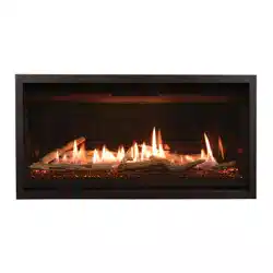
Model #SP34-L, SP34-MV
Direct Vent Gas Fireplace
English and French installation manuals are available
through your local dealer or website. Visit our website
www.kozyheat.com.
Les manuels d’installation en français et en anglais sont
disponibles chez votre détaillant local. Visitez
www.kozyheat.com.
⚠ WARNING: FIRE OR EXPLOSION
HAZARD
Failure to follow safety warnings exactly
could result in serious injury, death, or
property damage.
Do not store or use gasoline or other flam-
mable vapors and liquids in the vicinity of this
or any other appliance.
WHAT TO DO IF YOU SMELL GAS
• Do not try to light any appliance.
• Do not touch any electrical switch; do not
use any phone in your building.
• Leave the building immediately.
• Immediately call your gas supplier from a
neighbor’s phone. Follow the gas
supplier’s Instructions.
• If you cannot reach your gas supplier, call
the fire department.
Installation and service must be performed by
a qualified installer, service agency or the gas
supplier
This appliance may be installed in an aermarket, permanently
located, manufactured home (USA only) or mobile home, where
not prohibited by local codes.
This appliance is only for use with the type of gas indicated on the
rang plate. This appliance is not converble for use with other
gases, unless a cered kit is used.
INSTALLER: Leave this manual with the appliance.
CONSUMER: Retain this manual for future reference.
P.O. BOX 557 204 INDUSTRIAL PARK DRIVE
LAKEFIELD, MINNESOTA USA 56150-0577

Hussong Mfg. Co, Inc. 2 Rev. 10 - November 2023
SP-34, PFS Report No. 19-553 Starng Serial Number: 23 86710 49
Hussong Mfg. Co, Inc. 3 Rev. 10 - November 2023
SP-34, PFS Report No. 19-553 Starng Serial Number: 23 86710 49
CONGRATULATIONS!
Hussong Manufacturing welcomes you as a new owner of a Kozy Heat gas fireplace. Kozy Heat
products are designed with superior components and materials, assembled with care by trained crafts-
men who take pride in their work. To ensure you receive a quality product, the burner and valve as-
sembly are 100 percent test-fired, and the complete fireplace is thoroughly inspected before packag-
ing. Our commitment to quality and customer satisfaction has remained the same for over 40 years.
We offer a complete line of gas, wood, and electric fireplaces, along with stylish accessories to com-
plement any decor. Adding a fireplace is one of the best ways to increase the value of your home,
and we are proud to offer a network of dealers throughout the country to help make your experience
everything you imagine. We pride ourselves in being dedicated not only to functionality and reliability,
but also customer safety. We offer our continual support and guidance to help you achieve the maxi-
mum benefit and enjoyment from your Kozy Heat gas fireplace.
Jim Hussong
President
Dudley Hussong
Board Chairman
Homeowner Reference Informaon We recommend you record the following Informaon:
Model Name: ______________________________ Date Purchased / Installed: _______________________________
Serial Number: _____________________________ Locaon of replace: ____________________________________
Dealership purchased from: _________________________________________________________________________________
Dealership phone number: ____________________
Notes: __________________________________________________________________________________________________
________________________________________________________________________________________________________
________________________________________________________________________________________________________
Read this manual before installing or operang this appliance
Please retain this owner’s manual for future reference.

Hussong Mfg. Co, Inc. 4 Rev. 10 - November 2023
SP-34, PFS Report No. 19-553 Starng Serial Number: 23 86710 49

Hussong Mfg. Co, Inc. 5 Rev. 10 - November 2023
SP-34, PFS Report No. 19-553 Starng Serial Number: 23 86710 49
HOMEOWNER REFERENCE INFORMATION .................... 3
TABLE OF CONTENTS ..................................................... 5
1.0 Introducon ........................................................... 7
1.1 Appliance Cercaon .........................................7
1.2 California Proposion 65 Warning........................7
1.3 Requirements for the Commonwealth of
Massachuses ......................................................7
2.0 Specicaons ......................................................... 8
2.1 Heang Specicaons ..........................................8
2.2 Electrical Specicaons ........................................8
2.3 Appliance Dimensions ..........................................9
2.4 Safety Barrier Informaon ..................................10
3.0 Framing ................................................................ 11
3.1 Appliance Placement Consideraons .................11
3.2 Floor Support and Protecon .............................11
3.3 Seng the Appliance ..........................................11
3.4 Stand-O Assembly and Installaon ...................12
3.5 Nailing Flange Assembly and Installaon ...........13
3.6 Clearance to Combusbles .................................14
3.7 Wall Enclosure Rough Framing ...........................16
3.8 Vent Terminaon Framing ..................................17
3.9 Outdoor Covered Fireplace Installaon ..............18
4.0 Facing and Finishing ............................................. 20
4.1 Facing and Finishing Requirements ....................24
4.2 SP34-081 Exterior Trim Installaon ....................27
4.3 Safety Barrier Installaons..................................28
5.0 Gas Line Connecon ............................................. 29
5.1 Gas Conversions..................................................29
5.2 Gas Line Installaon ............................................29
6.0 Terminaon Locaons .......................................... 30
6.1 Vercal Vent Cap Terminaon............................30
6.2 Minimum Terminaon Clearances .....................31
7.0 Venng ................................................................. 32
7.1 Approved Vent Systems ......................................32
7.2 Venng Requirements ........................................33
7.3 Vent Restricon ..................................................34
7.4 Use of Flexible Venng Outside the
Appliance Enclosure ...........................................34
7.5 Natural Dra Co-Axial Pipe Installaons ............35
7.6 Class A Chimney / Masonry Conversion .............39
7.7 Co-Axial to Co-Linear Chimney Conversion ........40
7.8 #700-2 Series Horizontal Flex Vent
Terminaon Kit ........................................................... 41
8.0 Fireplace Setup ............................................................. 43
8.1 Glass Frame Assembly ................................................. 43
8.2 Components Access Panel Locaon ............................ 43
8.3 Hood Installaon ......................................................... 43
8.4 SP34-50A Log Set Installaon ...................................... 44
8.5 Control Board Removal and Installaon ..................... 46
8.6 #SP-028 Oponal Fan Kit (SP-34-MV Only) ................. 48
9.0 Electrical Informaon .................................................. 50
9.1 Electrical Specicaons ............................................. 50
9.2 Wiring Requirements ................................................ 50
10.0 Operang Instrucons for SP-34-L ............................... 53
10.1 Setup Proame 2 IFC Module .................................... 54
10.2 Inialize the Control System ...................................... 54
10.3 Reset the System for Manual Operaon ................... 54
10.4 Automac Safety Turn-o ......................................... 54
10.5 Backup Baery Operaon ......................................... 54
10.6 Control System 7 Day Timeout .................................. 55
10.7 IFC Module Ignion Sequence ................................... 55
10.8 Addional Diagnosc Informaon ............................ 55
10.9 Remote Control Operaon ........................................ 56
11.0 Operang Instrucons for SP-34-MV ............................ 60
11.1 Flame Height and Heat Output Adjustment ............. 61
11.2 7 Day Time-out Pilot-on-Demand Installaon .......... 61
12.0 Pressure Tesng and Burner Adjustments ................... 62
12.1 Pressure Tesng - IPI System ..................................... 62
12.2 Pressure Tesng - MV System ................................... 63
12.3 Flame Appearance Adjustment ................................. 64
13.0 Troubleshoong .......................................................... 66
13.1 Electronic Ignion System (SP-34-L) ......................... 66
13.2 Millivolt Ignion System (SP-34-MV) ........................ 69
14.0 Maintenance ............................................................... 72
14.1 Firebox ....................................................................... 72
14.2 Fan ............................................................................. 72
14.3 Vent System ............................................................... 72
14.4 Glass Assembly .......................................................... 72
14.5 Burner and Pilot System ............................................ 73
15.0 Replacement Parts List ................................................ 74
Limited Lifeme Warranty ................................................... 77
TABLE OF CONTENTS

Hussong Mfg. Co, Inc. 6 Rev. 10 - November 2023
SP-34, PFS Report No. 19-553 Starng Serial Number: 23 86710 49

Hussong Mfg. Co, Inc. 7 Rev. 10 - November 2023
SP-34, PFS Report No. 19-553 Starng Serial Number: 23 86710 49
1.1 Appliance Cercaon
Laboratory: PFS in Coage Grove, Wisconsin
Standards:
• ANSI Z21.88-2019/CSA 2.33-2019, Vented Gas Fireplace
Heaters
• CSA 2.17 2017, Gas-Fired Appliances for Use at High
Altudes
This installaon must conform with local codes, or in the
absence of local codes, with the Naonal Fuel Gas Code,
ANSI Z223.1/NFPA 54, or the Natural Gas and Propane In-
stallaon Code, CSA B149.1.
1.2 California Proposion 65 Warning
⚠ WARNING: This product can expose you to chemicals
including Carbon Monoxide, that is an externally vented by-
product of fuel combuson, which is [are] known to the
State of California to cause birth defects or other reproduc-
ve harm. For more informaon, visit
www.P65Warnings.ca.gov.
1.3 Requirements for the Commonwealth of
Massachuses
The following requirements reference various Massachu-
ses and naonal codes not contained in this manual.
For all sidewall horizontally vented gas fueled equipment
installed in every dwelling, building or structure used in
whole or in part for residenal purposes, including those
owned or operated by the Commonwealth and where the
side wall exhaust vent terminaon is less than (7) feet
above nished grade in the area of the venng, including
but not limited to decks and porches, the following require-
ments shall be sased:
1.3.1 Installaon of Carbon Monoxide
Detectors
At me of installaon of side wall horizontally vented gas
fueled equipment, the installing plumber or gas-er shall
observe that a hard wired carbon monoxide detector with
an alarm and baery back-up is installed on the oor level
where the gas equipment is to be installed. In addion, the
installing plumber or gas-er shall observe that a baery
operated or hard wired carbon monoxide detector is in-
stalled on each addional level of the dwelling, building or
structure served by the side wall horizontal vented gas
fueled equipment. It shall be the responsibility of the prop-
erty owner to secure the services of qualied licensed pro-
fessionals for the installaon of hard wired carbon monox-
ide detectors.
In the event that the side wall horizontally vented gas
fueled equipment is installed in a crawl space or ac, the
hard wired carbon monoxide detector with alarm and
baery back-up may be installed on the next adjacent oor
level. In the event that the requirements of this subdivision
can not be met at the me of compleon of installaon, the
owner shall have a period of thirty (30) days to comply with
the above requirements; provided, however, that during
said thirty (30) day period, a baery operated carbon mon-
oxide detector with an alarm shall be installed.
1.3.2 Approved Carbon Monoxide Detectors
Each carbon monoxide detector as required in accordance with
the above provisions shall comply with NFPA 720 and be ANSI/UL
2034 listed and IAS cered.
1.3.3 Signage
A metal or plasc idencaon plate shall be permanently
mounted to the exterior of the building at a minimum of eight (8)
feet above grade directly in line with the exhaust vent terminal
for the horizontally vented gas fueled heang appliance or
equipment. The sign shall read, in print no less the one-half inch
(½) in size, “GAS VENT DIRECTLY BELOW. KEEP CLEAR OF ALL OB-
STRUCTIONS”.
1.3.4 Inspecon
The state or local gas inspector of the side wall horizontally vent-
ed gas fueled equipment shall not approve the installaon un-
less, upon inspecon, the inspector observes carbon monoxide
detectors and signage installed in accordance with the provisions
of 248 CMR 5.08 (2) (a) 1 through 4.
1.3.5 Exempons
The following equipment is exempt from 248 CMR 5.08 (2) (a) 1
through 4: The equipment listed in Chapter 10 entled
“Equipment Not Required To Be Vented” in the most current
edion of NFPA 54 as adopted by the Board; and Product Ap-
proved side wall horizontally vented gas fueled equipment in-
stalled in a room or structure separate from the dwelling, build-
ing or structure used in whole or in part for residenal purposes.
1.3.6 Manufacturer Requirements
1.3.6.1 Gas Equipment Venng System Provided
When the manufacturer of Product Approved side wall horizon-
tally vented gas equipment provides a venng system design or
venng system components with the equipment, the instruc-
ons provided by the manufacturer for installaon of the equip-
ment and the venng system shall include:
• Detailed instrucons for the installaon of the venng sys-
tem design or the venng system components; and
• A complete parts list for the venng system design or
venng system.
1.3.7 Gas Equipment Venng System NOT Provided
When the manufacturer of Product Approved side wall horizon-
tally vented gas equipment does not provide the parts for
venng the ue gases, but idenes “special venng systems”,
the following requirements shall be sased by the manufactur-
er:
• The referenced “special venng systems” instrucons shall
be included with the appliance or equipment installaon
instrucons and;
• The “special venng systems” shall be Product Approved by
the Board, and the instrucons for that system shall include
a parts list and detailed installaon instrucons.
A copy of all installaon instrucons for all Product Approved
side wall horizontally vented gas fueled equipment, all venng
instrucons, all parts lists for venng instrucons, and/or all
venng design instrucons shall remain with the appliance or
equipment at the compleon of the installaon.
1.0 Introducon
Hussong Mfg. Co, Inc. 8 Rev. 10 - November 2023
SP-34, PFS Report No. 19-553 Starng Serial Number: 23 86710 49
2.0 Specicaons
2.1 Heang Specicaons
2.1.1 Altude Adjustment
This appliance may be installed at higher altudes. Please refer to Naonal Fuel Gas Code ANSI Z223.1/NFPA 54, CSA-B149.1
Natural Gas and Propane Installaon Code, local authories, or codes having jurisdicon in your area regarding derate
guidelines.
2.1.1.1 US Installaons
Refer to the American Gas Associaon guidelines for the gas designed appliances derang method. For elevaons above
2,000’ (610m), input rangs are to be reduced by 4% for each 1,000’ (305m) above sea level.
2.1.1.2 Canadian Installaons
When the appliance is installed at elevaons above 4,500’ (1,372m), the cered high-altude rang shall be reduced at the
rate of 4% for each addional 1,000’ (305m).
2.2 Electrical Specicaons
• The juncon box in this appliance requires 120VAC, 60Hz, and 6 Amps.
• Verify the household breaker is shut o prior to working on any electrical lines.
• SP-34-L
• The AC power supply to this appliance must be hot at all mes and shall not have a switch installed in it.
• SP-34-MV
• Electrical specicaons ONLY apply to when the oponal fan kit (#SP-028) is used.
SP-34-L SP-34-MV
Natural Gas Propane Natural Gas Propane
Maximum Input Rang 20,500 Btu/h
(6.0 kW)
20,500 Btu/h
(6.0 kW)
20,500 Btu/h
(6.0 kW)
20,500 Btu/h
(6.0 kW)
Orice Size (DMS) #46 #55 #46 #55
Minimum Input Rang 14,000 Btu/h
(4.10 kW)
15,000 Btu/h
(4.40 kW)
14,000 Btu/h
(4.10 kW)
15,000 Btu/h
(4.40 kW)
Minimum Inlet Pressure 5” WC (1.25 kPa)
7” WC (1.74 kPa)
recommended
11”WC (2.74 kPa) 5” WC (1.25 kPa)
7” WC (1.74 kPa)
recommended
11”WC (2.74 kPa)
Maximum Inlet Pressure 10”WC (2.49 kPa) 13”WC (3.24 kPa) 10”WC (2.49 kPa) 13”WC (3.24 kPa)
Manifold Pressure (High) 3.5” WC (0.87 kPa) 10” WC (2.48 kPa) 3.5” WC (0.87 kPa) 10” WC (2.48 kPa)
Manifold Pressure (Low) 1.6” WC (0.41 kPa) 6.4” WC (1.59 kPa) 1.6” WC (0.41 kPa) 6.4” WC (1.59 kPa)
Venturi Opening Sengs 1/16” (1.5mm) 5/8” (16mm)*
*Fully Open
1/16” (1.5mm) 5/8” (16mm)*
*Fully Open
Hussong Mfg. Co, Inc. 9 Rev. 10 - November 2023
SP-34, PFS Report No. 19-553 Starng Serial Number: 23 86710 49
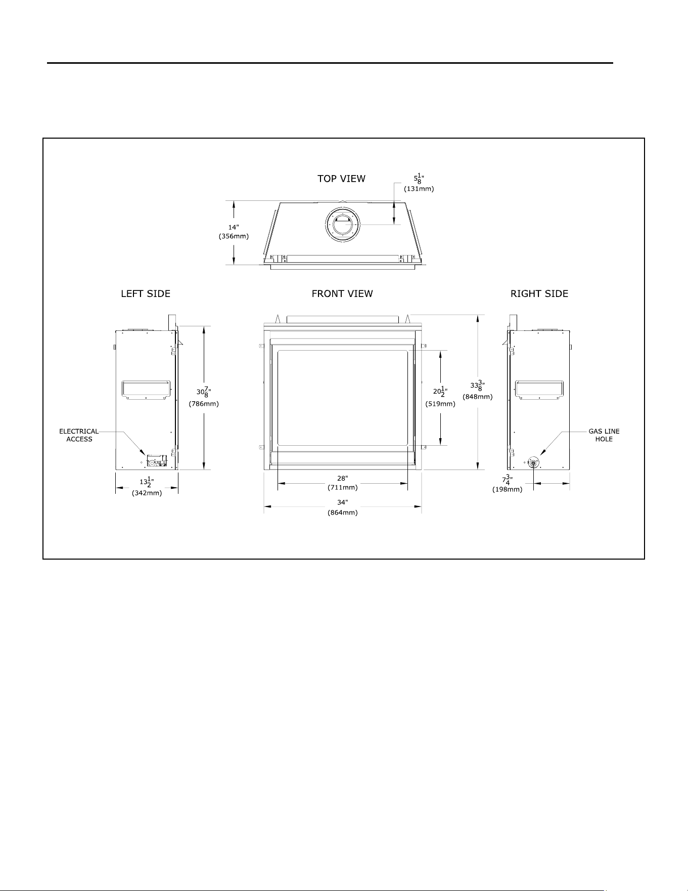
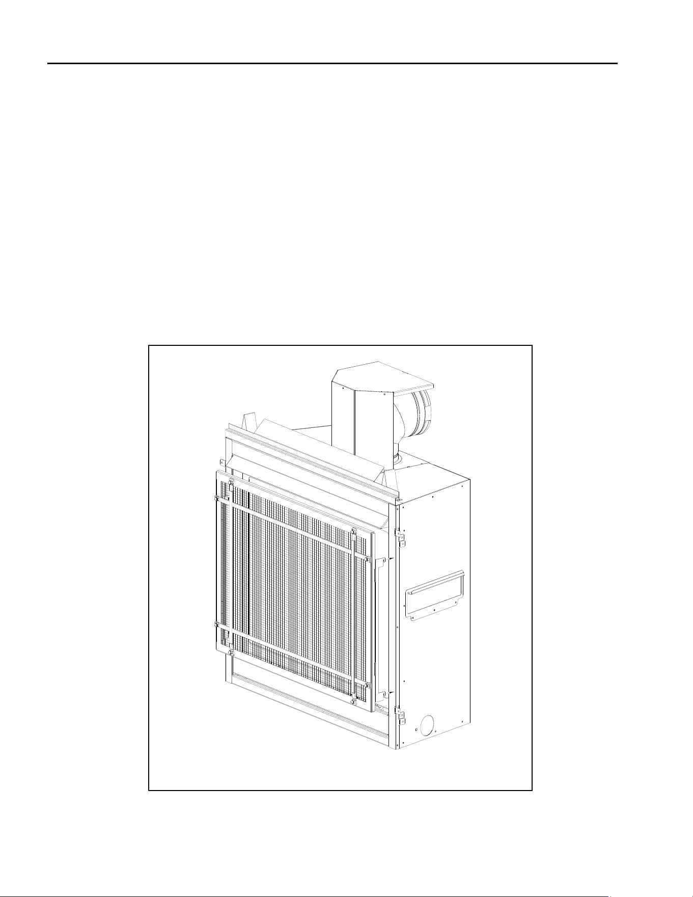
2.3 Appliance Dimensions
Figure 2.1 - Appliance Dimensions
Hussong Mfg. Co, Inc. 10 Rev. 10 - November 2023
SP-34, PFS Report No. 19-553 Starng Serial Number: 23 86710 49
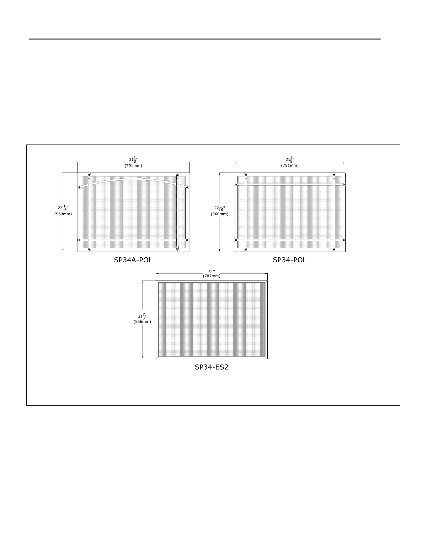
2.4 Safety Barrier Informaon
WARNING: A barrier designed to reduce the risk of
burns from the hot viewing glass is provided with this
appliance and shall be installed for the protecon of
children and other at-risk individuals.
If the barrier becomes damaged, the barrier shall be
replaced with Hussong Mfg.’s barriers for this appliance.
Please refer to Secon 4.3 Safety Barrier Installaons for
mounng and installaon opons.
NOTE: The appliance includes the standard screen barrier
(SP34-ES2) preinstalled. There are oponal decorave overlays
for the appliance which are installed on top of the provided
screen barrier. See SP34A-POL or SP34-POL.
Figure 2.2 - Safety Barriers Group #1

Hussong Mfg. Co, Inc. 11 Rev. 10 - November 2023
SP-34, PFS Report No. 19-553 Starng Serial Number: 23 86710 49
3.0 Framing
3.1 Appliance Placement Consideraons
Read all documentaon for your specic installaon and
design opons prior to appliance installaon.
WARNING: Due to high temperatures, the appliance
should be located out of trac and away from furniture
and draperies.
FIRE HAZARD: Do NOT install this appliance directly on
carpeng, vinyl, or any other combusble material other
than wood.
Note: Unless otherwise noted all clearances / images in this
manual are based o of nominal 2” x 4” framing being used.
• This appliance must be installed on a level surface ca-
pable of supporng the replace and venng. If possi-
ble, place the replace in a posion where the vent
terminates between two studs, eliminang the need
for any addional framing.
• This replace may be installed in a bedroom.
• Please be aware of the large amount of heat this re-
place will produce when determining a locaon.
3.2 Floor Support and Protecon
• Floor protecon in front of the replace is not required.
Combusble material may be used if installing a hearth
extension. Consider the thickness of the hearth exten-
sion nishing material if building a replace plaorm.
The boom of the replace must be level with nished
hearth extension for proper t of a safety barrier.
• If this appliance is to be installed directly on carpeng,
le, or other combusble material other than wood
ooring, this appliance shall be installed on a metal or
wood panel extending the full width and depth of the
appliance.
• If the appliance is to be installed above oor level, a
solid, connuous plaorm must be constructed below
the appliance.
3.3 Seng the Appliance
• This secon outlines informaon on seng the appliance in the
framed opening and starng the installaon process. .
General Procedure
Frame your opening. Refer to Secon 3.7 for informaon for
the framed opening.
Lay out the path for your vent run before installing appliance.
We recommend understanding how this appliance has dierent
posions to set the appliance in the framed opening depending
on how you want your nishing material to bu up against the
appliance or overlap the allowed perimeter of the appliance.
See Secon 4.0 for more informaon.
Install the nailing anges on the appliance. Refer to Secon 3.5
for assembly and installaon. The nailing anges are where you
secure your appliance to the framed opening. The framing will
be ush with the appliance when it is installed.
Assemble and install the top header stand-o assembly. Refer
to Secon 3.4 for more informaon on the top stand-o assem-
bly. This stand-o assembly provides the necessary thermal
protecon of the header.
Place the replace inside the framed opening and secure the
appliance into the framing.
The next steps would involve installing the vent pipe,
connecng gas line, connecng electrical wiring, and nally
nishing material.
Hussong Mfg. Co, Inc. 12 Rev. 10 - November 2023
SP-34, PFS Report No. 19-553 Starng Serial Number: 23 86710 49
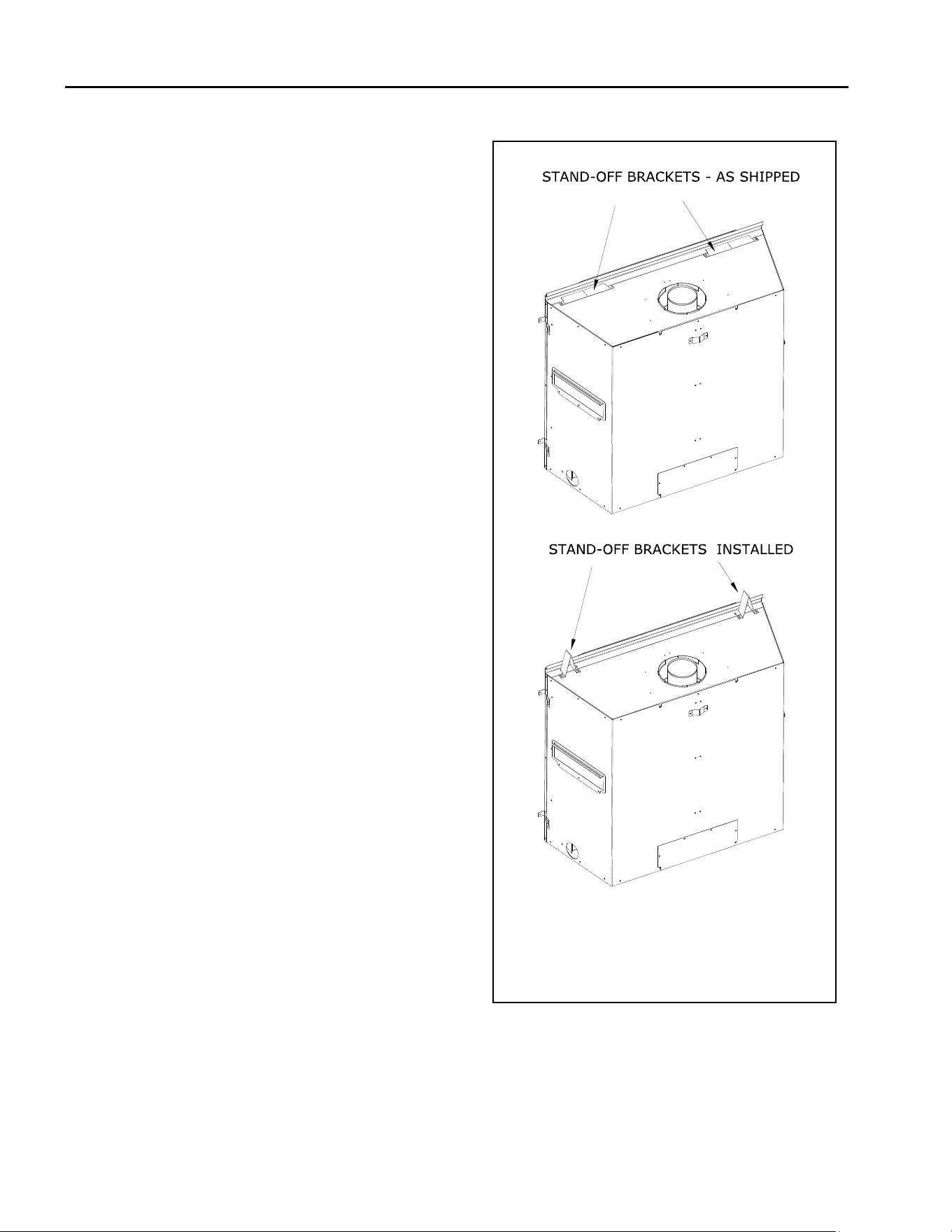
3.4 Stand-O Assembly and Installaon
WARNING: The top stand-os provide the 3-1/2” (89mm)
minimum clearance to the header. The 1” (25mm) top
stand-o ange accommodates 1/2” (12mm) combusble
facing material (sheetrock). The clearance to here must be
maintained
Top stand-o brackets must be formed and aached prior
to posioning replace into framed opening.
Installaon:
1. Remove and save (4) screws securing stand-o
brackets on top of the replace.
2. Form each top stand-o bracket by bending at
perforaons, as shown.
3. Align the holes in the formed top stand-os with the
holes in the replace top. Secure with the (4) screws
previously removed.
Figure 3.1 - Stand-O Installaon
Hussong Mfg. Co, Inc. 13 Rev. 10 - November 2023
SP-34, PFS Report No. 19-553 Starng Serial Number: 23 86710 49
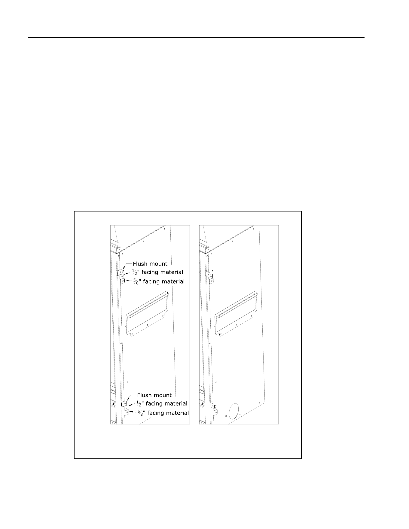
3.5 Nailing Flange Installaon
The nailing ange tabs on both sides of the appliance
allow for dierent posions in the framed opening. You
can aach the appliance to the framed opening:
• Flush mount
• Recessed 1/2” (13mm) for facing material
• Recessed 5/8” (16mm) for facing material
Note: The recessed installaons allow nishing material
to bu up ush against the side of the appliance. The
ush mount framed installaon would have the nish-
ing material overlap the front of the appliance. The n-
ishing material cannot overlap the component access
panel or the safety barrier. See Secon 4.1 Facing and
Finishing Requirements.
CAUTION: Never permanently remove these assemblies
from the replace. They must be secured regardless
of nish material used.
Important Finishing Material Consideraon:
Combusble nishing material must bu up against and stop
at the edge of the replace. See Figure 4.2 and 4.3.
Noncombusble nishing material can overlap the appliance
edge. See Figure 4.4.
Instrucons:
1. Locate the nailing tabs on the right and le side of the
replace necessary to accommodate the thickness of
your facing material.
2. Bend out the (4) nailing tabs unl parallel with replace
face. Do not bend toward replace face.
3. When installing, center the replace in the rough open-
ing to allow for the minimum 1/4” (6mm) clearance from
the appliance corners.
4. Secure the appliance to the framing studs by using nails
or screws through the nailing tabs.
Figure 3.2 - Nailing Flange Installaon
Hussong Mfg. Co, Inc. 14 Rev. 10 - November 2023
SP-34, PFS Report No. 19-553 Starng Serial Number: 23 86710 49
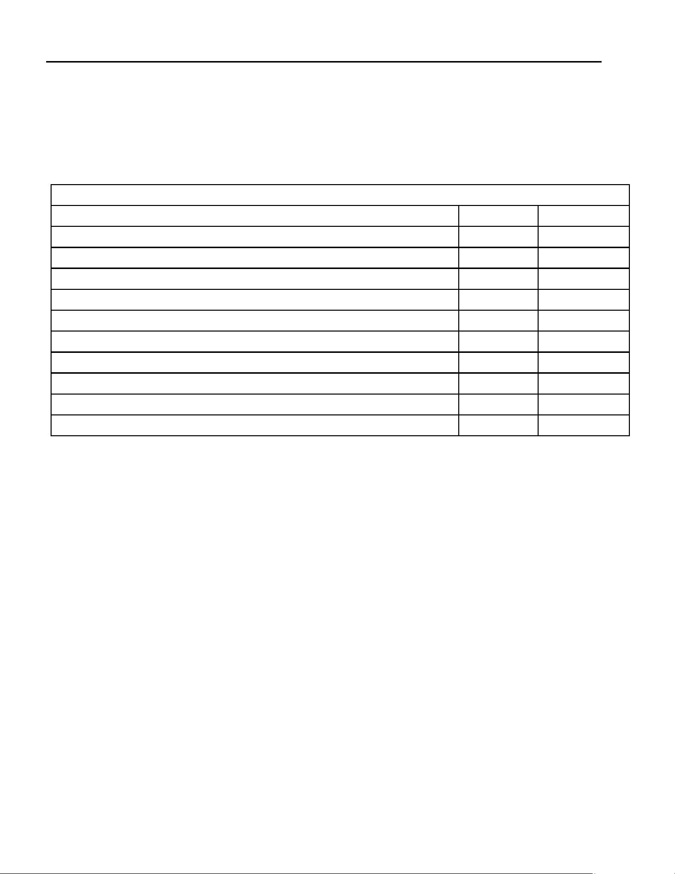
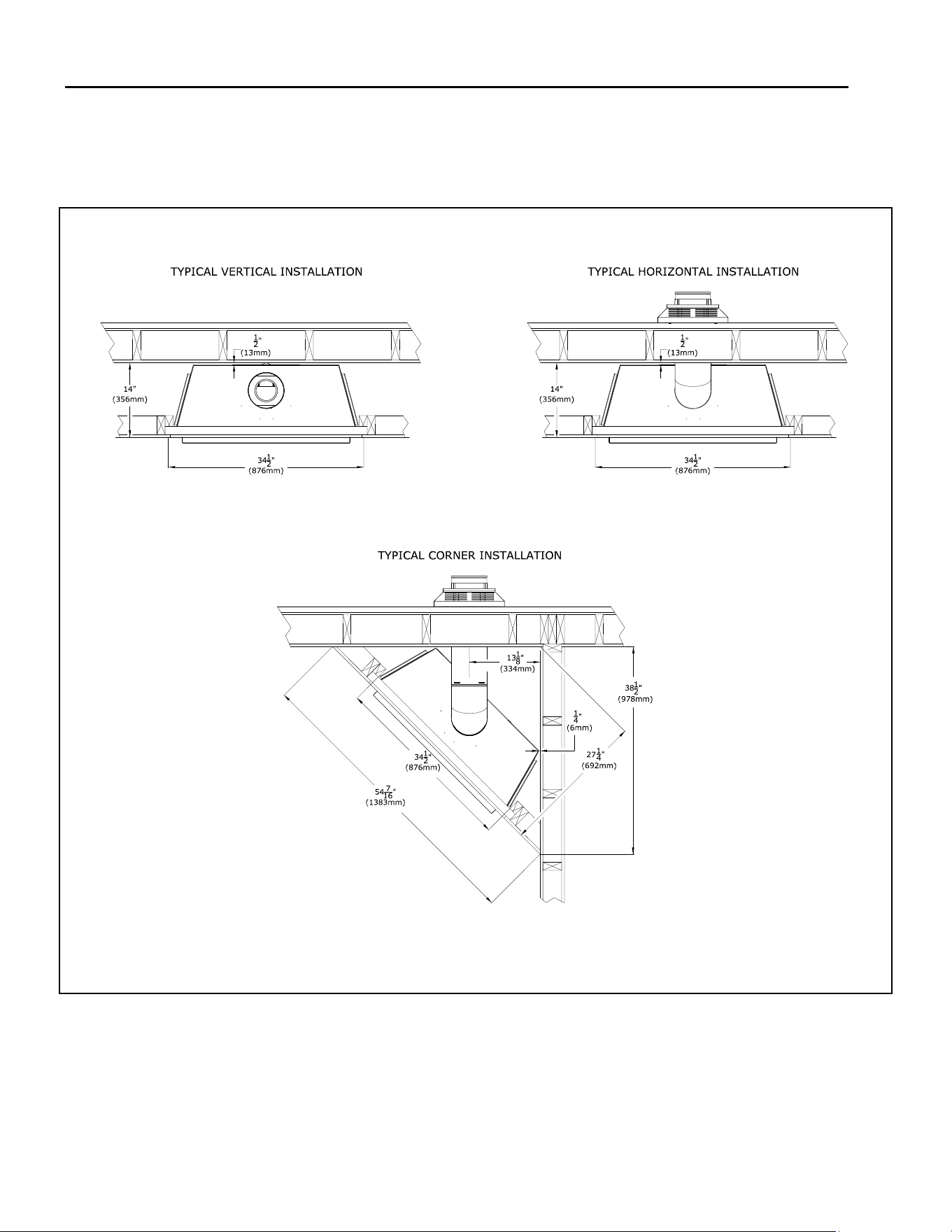
3.6 Clearances to Combusbles
Table 3.1, Minimum Fireplace Clearances to Combusble Material
Minimum height of replace enclosure 42” 1076mm
Minimum width of replace enclosure 34-1/2” 876mm
Minimum depth of replace enclosure 14” 356mm
From replace top stand-o brackets 0” 0mm
From replace le and right stand-o brackets (nailing anges) 0” 0mm
From replace back stand-o brackets 0” 0mm
From replace corners 1/4” 6mm
From replace front 36” 914mm
Fireplace sides to adjacent sidewall 4-1/2” 114mm
Fireplace enclosure oor to 3/4” (19mm) mantel trim 33-1/2” 851mm
Fireplace enclosure oor to 6” (152mm) mantel projecon 37” 940mm
• See Table 3.1 below for minimum clearances for the standard installaon opon.
• See Figure 3.3 on the following pages for typical standard installaon opons.
• Unless otherwise noted all clearances / images in this manual are based o of nominal 2” x 4” framing being used.
Hussong Mfg. Co, Inc. 15 Rev. 10 - November 2023
SP-34, PFS Report No. 19-553 Starng Serial Number: 23 86710 49
Figure 3.3 - Typical Appliance Installaon
Hussong Mfg. Co, Inc. 16 Rev. 10 - November 2023
SP-34, PFS Report No. 19-553 Starng Serial Number: 23 86710 49
3.7 Wall Enclosure Rough Framing
Note: Unless otherwise noted all clearances / images in this
manual are based o of nominal 2” x 4” framing being used.
3.7.1 Rough Framing
WARNING: Provide adequate clearances around air openings
into the combuson chamber. Provide adequate clearance in
front of the replace for barrier removal, component access,
gas line installaon, service access, etc.
CAUTION: Cold air transfer area. The surround replace
chase must comply with all clearances as outlined in this
manual, and be constructed in compliance with local
building codes. Outside walls should be insulated to prevent
cold air from entering room.
Rough-in dimensions outlined in FIGURE 3.4 below are the
same for all design opons and must be followed.
• Floor protecon in front of the replace is not required.
Combusble material may be used if installing a hearth
extension. Consider the thickness of the hearth
extension nishing material if building a replace
plaorm. The hearth may be ush with the boom
nishing edge of the replace. You cannot cover the
access cover.
• The boom of the replace must be placed directly on a
wood or non-combusble surface (not linoleum or
carpet). If this appliance is to be installed directly on
carpeng, le, or other combusble material other than
wood ooring, this appliance shall be installed on a
metal or wood panel extending the full width and depth
of the appliance.
• Framing dimensions should allow for wall covering
thickness and replace facing materials.
• If masonry (oponal) is to be used, prepare the foundaon
necessary for the full masonry load. A lintel must be used
over the top of the appliance to support the added weight
of the masonry construcon above the replace.
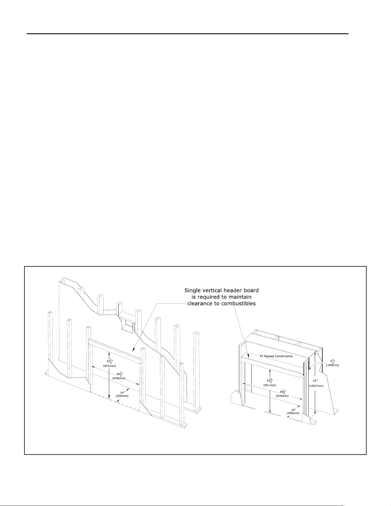
3.7.2 Mounng a Television Above a Fireplace and
Television Recess Construcon
WARNING: All clearances to venng must be maintained.
• Mounng a television above a replace is a common
pracce. Mantel depth, ceiling heights, and wall and mantel
construcon material all aect television surface tempera-
tures. Most television manufacturers specify in their
instrucons that a television should not be installed on,
near, or above a heat source.
• We recommend the use of a mantel to deect heat away
from the television.
• Television locaon rests solely on the homeowner. It is the
home owner’s responsibility that the preferred TV
mounng and mantel design will not exceed the listed
maximum operaon temperature of their electronic goods.
Figure 3.4 - Minimum Appliance Framing
Hussong Mfg. Co, Inc. 17 Rev. 10 - November 2023
SP-34, PFS Report No. 19-553 Starng Serial Number: 23 86710 49
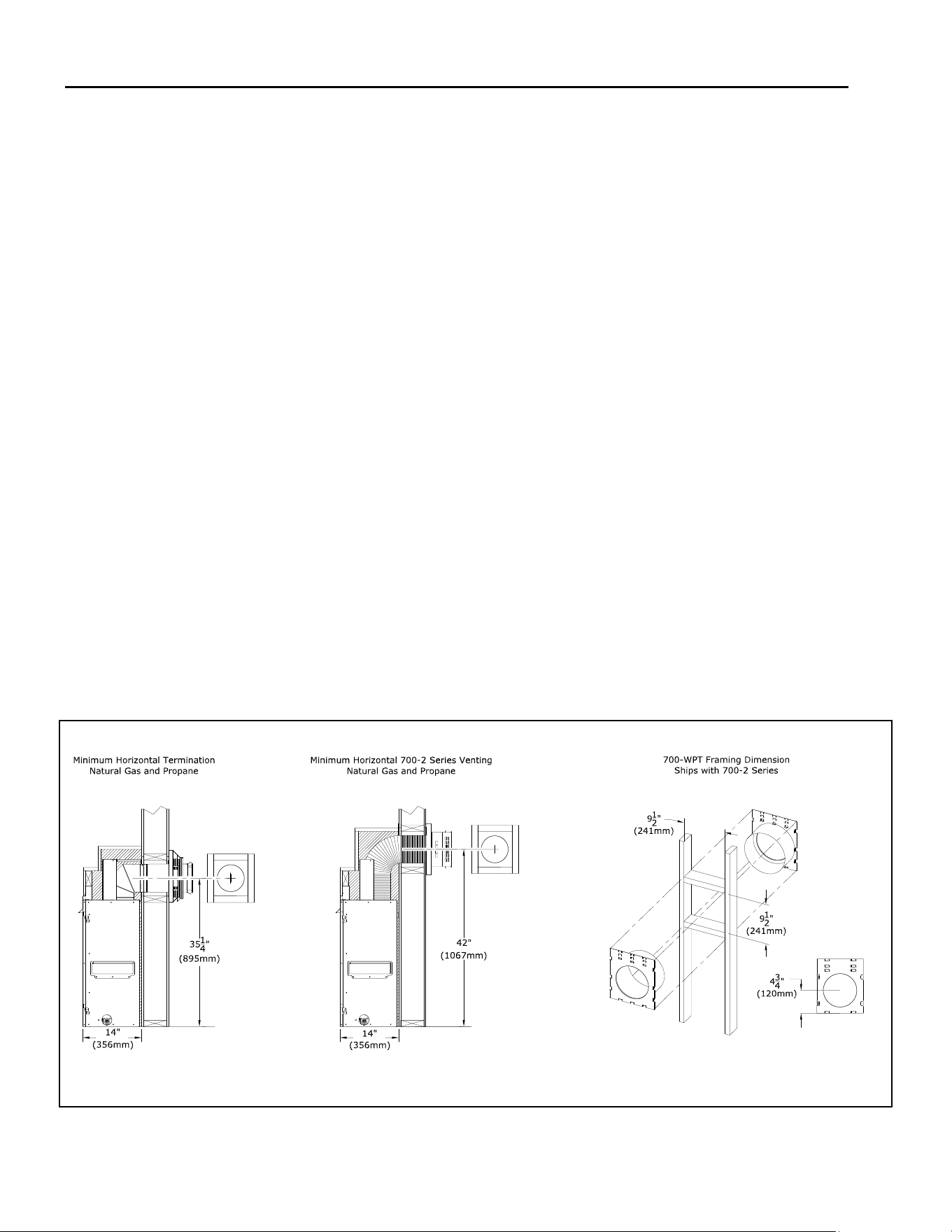
Figure 3.5 - Horizontal Vent Pipe Clearance
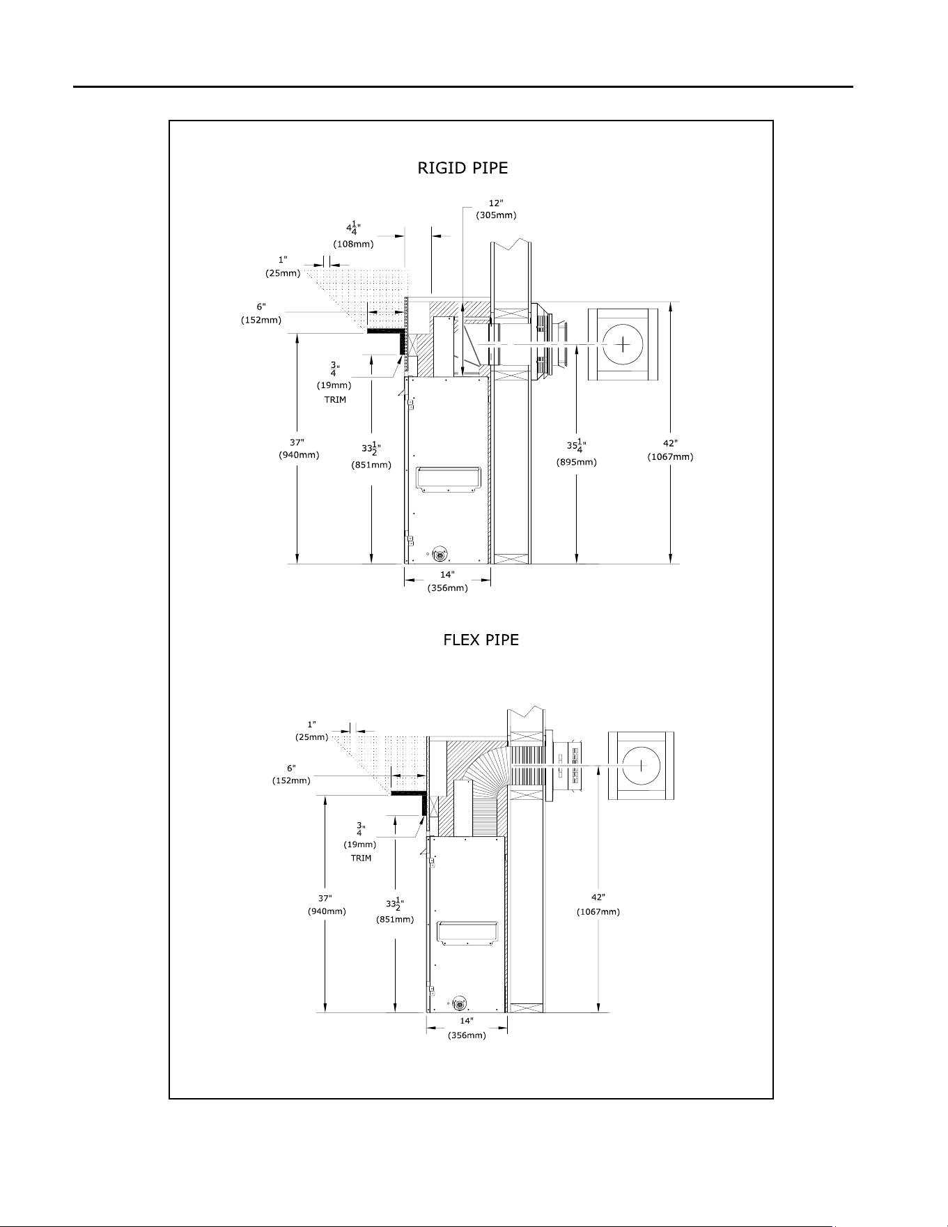
3.8 Vent Terminaon Framing
3.8.1 Vent Terminaon Locaon
• Exterior vent terminaon locaon must be in compli-
ance with secon 6.0, TERMINATION LOCATIONS.
3.8.2 Clearances
• A minimum of 1” (25mm) clearance on all sides of the
vercal vent pipe must be maintained.
Refer to FIGURE 3.5 below for the following clearances
• A minimum of 1” (25mm) clearance on the top, sides,
and boom surfaces on the horizontal pipe must be
maintained.
NOTE: Elbows listed with approved vent systems for this
appliance vary in vercal length. Please consult the vent
manufacturer’s instrucons to determine the elbow dimen-
sion used for installaon. Adjust the wall pass-through
rough opening dimensions as necessary to maintain clear-
ance requirements.
3.8.3 Vercal Terminaons
• Follow vent pipe manufacturer’s installaon instruc-
ons for vercal terminaons.
• Ac insulaon shields may be insulated using unfaced
insulaon products listed as non-combusble per ASTM
E 136
3.8.4 Horizontal Terminaons
WARNING: Do not recess the vent cap into wall or siding.
IMPORTANT: Horizontal vent secons require 1/4” (6mm)
rise for every 12” (305mm) of travel for natural dra appli-
caons.
Wall thimble products that comply with the required 1” (25mm)
top clearance to combusbles must be installed for all horizontal
vent runs that pass through interior or exterior walls. These wall
thimble products may be insulated using unfaced insulaon
products listed as noncombusble per ASTM E 136.
Elbows listed with approved vent systems for this appliance vary
in vercal length. Please consult the vent manufacturer’s instruc-
ons to determine the elbow dimension used for installaon.
Adjust the wall pass-through rough opening dimensions to main-
tain clearance requirements.
Kozy Heat’s #700-WPT, or wall thimble products that comply
with the required 1” (25mm) top clearance to combusbles,
must be installed for all horizontal vent runs that pass through
interior or exterior walls. These wall thimble products may be
insulated using unfaced insulaon products listed as noncom-
busble per ASTM E 136. Wall Thimble #700-WPT is designed for
wall thickness that is 4” (101mm) to 6-1/2” (165mm)
Flexible pipe framing dimensions are tested with Kozy Heat #700
-2 Series Flexible Vent System. See the drawing below.
3.8.5 Wall Pass Through Framing Instrucons
Follow FIGURE 3.6 below for minimum rough-in dimensions.
1. Measure from oor level of the replace to the center of
where the vent pipe will penetrate the wall. The dimension
in FIGURE 3.5 is used with a Simpson DuraVent elbow.
2. Cut and frame an opening in the wall to allow the vent sys-
tem to run level through the wall pass-through.
3. Follow the vent pipe manufacturer’s installaon instrucons
for natural dra vent installaon.
Note: Vent pipe dimensions are tested with listed Simpson Du-
raVent pipe. Other manufacturers product dimensions may
vary.
Hussong Mfg. Co, Inc. 18 Rev. 10 - November 2023
SP-34, PFS Report No. 19-553 Starng Serial Number: 23 86710 49
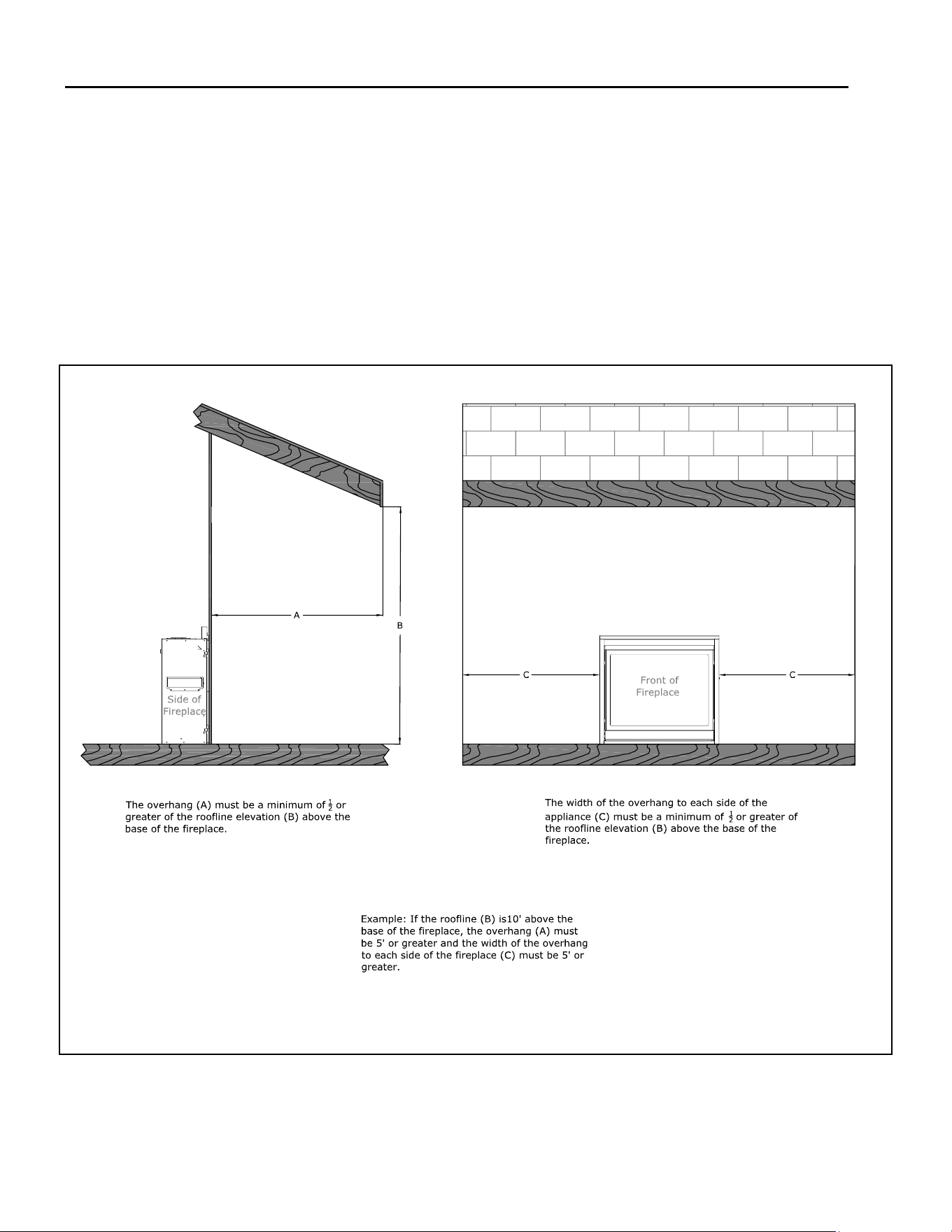
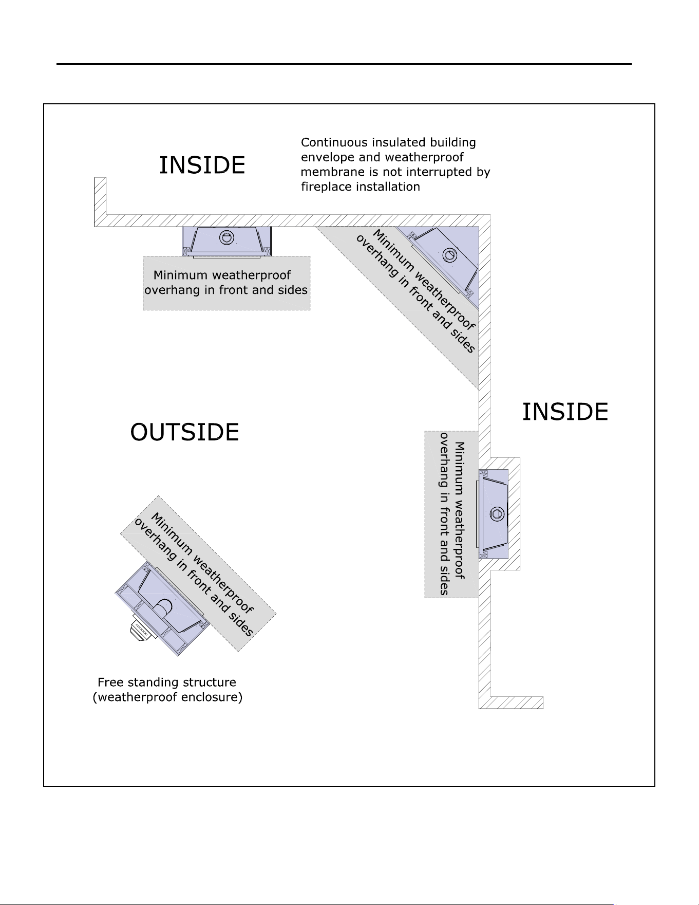
3.9 Outdoor Covered Fireplace Installaon
A outdoor covered replace installaon allows a replace
to be installed in an outdoor covered area, where the
appliance is protected from direct precipitaon.
Follow the instrucons and illustraons in this secon for
installaon procedures.
3.9.1 Safety Screen Barriers
Hussong Mfg. highly recommends to use black painted
safety barriers in outdoor installaons. Other screen bar-
riers that incorporate a plated or pana nish are highly
suscepble to oxidaon and discoloraon.
3.9.2 Requirements
• The connuous insulated building envelope and weather-
proof membrane are not to be interrupted by replace
installaon.
• Fireplace operaon is approved from 40°F to 110°F.
• All wiring connecons shall be in accordance with out-
door requirements of NECA NFPA 70.
• All clearances and requirements in your appliance manual
must be adhered to.
Figure 3.7 - Outdoor Covered Installaon
Hussong Mfg. Co, Inc. 19 Rev. 10 - November 2023
SP-34, PFS Report No. 19-553 Starng Serial Number: 23 86710 49
Figure 3.8 - Outdoor Covered Installaon

Hussong Mfg. Co, Inc. 20 Rev. 10 - November 2023
SP-34, PFS Report No. 19-553 Starng Serial Number: 23 86710 49
4.0 Facing and Finishing
4.1 Facing and Finishing Requirements
WARNING: Maintain all minimum clearances to combus-
bles from the appliance and vent system.
Ensure nishing material does not inhibit the installaon
and removal of the safety barrier (See Secon 2.4).
Finishing material cannot obstruct venlaon air.
4.1.1 Combusble Hearth and Mantel
Requirements
WARNING: All minimum clearances to combusble
material MUST be maintained.
• Combusble Mantel Projecons: As referenced in
FIGURE 4.1, the 3/4” (19mm) trim can start at 33-
1/2” (851mm) above the replace enclosure oor
with a 6” (152mm) mantel starng at 37” (940mm)
above the replace enclosure oor. Mantel projec-
ons can increase 1” (25mm) of depth for every
1” (25mm) of height starng at 6” (152mm) mantel.
• Combusble Hearth: Combusble ooring can run
underneath this appliance which would then allow an
unlimited combusble hearth projecon. The hearth
projecon cannot be elevated (vercally) past the
base of the replace / enclosure oor.
• Mantel Leg: Follow "Side Combusble Clearance"
below. See FIGURE 4.5.
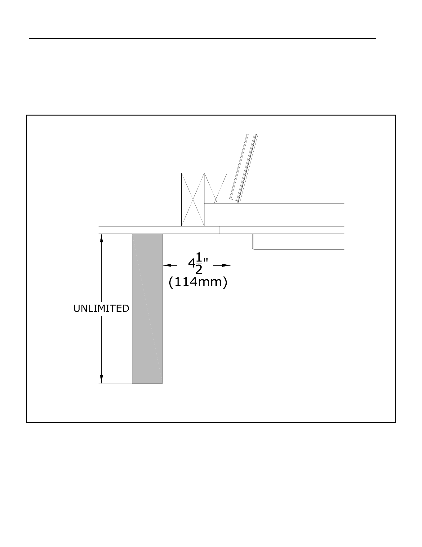
• Combusble Sidewall Clearance: the adjacent
sidewall projecon is unlimited and starts at 4-
1/2” (114mm) from the side of the replace. See FIG-
URE 4.5.
4.1.2 Non-combusble Mantel Requirements
• Noncombusble Mantel Projecons: A 6” (152mm)
noncombusble mantel projecon can start 6” above
the top nishing edge of the replace.
• Follow projecon 1” (25mm) up for every 1” (25mm)
deeper.
4.1.3 Finishing Recommendaons
NOTE: The surface area above the appliance may be aected
by high temperatures emied from this appliance. To help
avoid or reduce the possibility of the sheetrock to crack,
Hussong Mfg. recommends the following methods:
• Ensure the non-combusble material and sheetrock is dry
and dust free.
• For taping and mudding seams, we recommend heat
resilient tape, mesh and joint compounds, such as
Durabond. Mud must be cured as per manufacturers
recommendaons.
• For a painted surface, use a high quality acrylic latex
primer and nish coat. Avoid at or light-colored paints to
prevent discoloring.
Disclaimer: Kozy Heat does not guarantee any materials used
around the replace. Kozy Heat disclaims any and all liability
for any damage to nishing materials including warping,
discoloring, cracking, peeling or aking. This also includes any
o-gassing or unpleasant smells from materials when they are
heated.
Hussong Mfg. Co, Inc. 21 Rev. 10 - November 2023
SP-34, PFS Report No. 19-553 Starng Serial Number: 23 86710 49
Figure 4.1 - Mantel Projecons
Hussong Mfg. Co, Inc. 22 Rev. 10 - November 2023
SP-34, PFS Report No. 19-553 Starng Serial Number: 23 86710 49
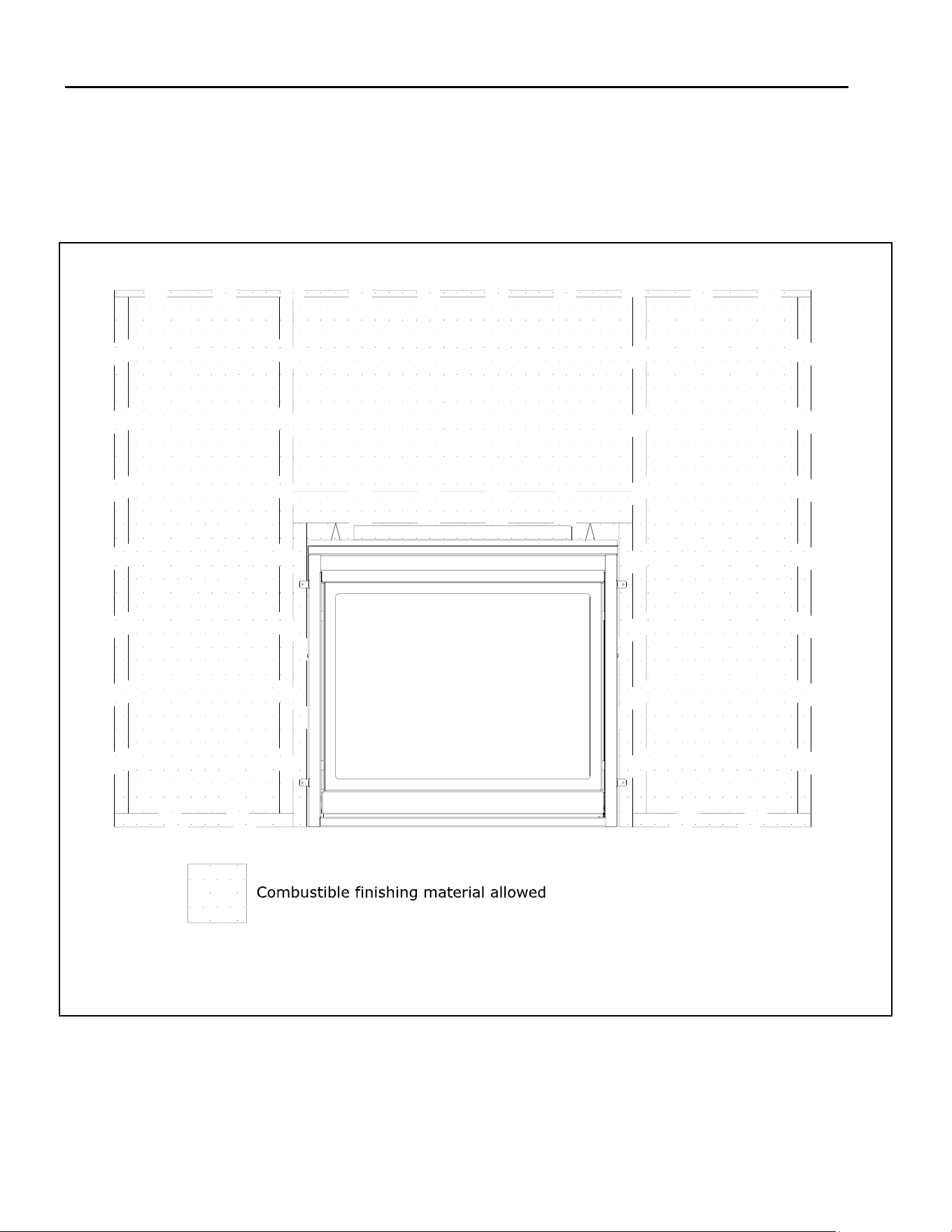
Figure 4.2 - Combusble Finishing Material
Note: Shown below (Figure 4.2) is where combusble nishing material is allowed. Combusble nishing materi-
al is allowed to bu up against the appliance. Figure 4.3 shows a side prole of how the combusble nishing
material bus up against the top nishing material stando.
Hussong Mfg. Co, Inc. 23 Rev. 10 - November 2023
SP-34, PFS Report No. 19-553 Starng Serial Number: 23 86710 49
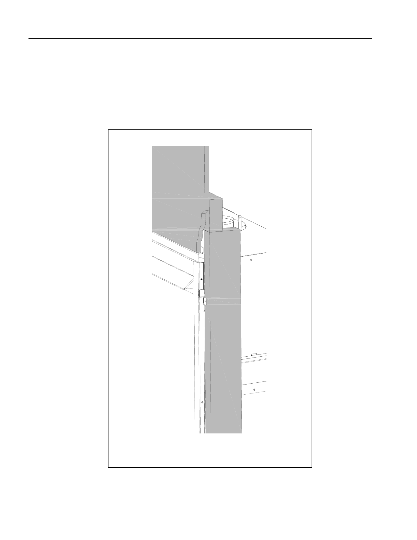
Note: Figure 4.3 shows the facing material ush with the appliance.
• The top of the appliance has a 1” stando where the combusble facing material bus up against.
Figure 4.3 - Combusble Finishing Material
Hussong Mfg. Co, Inc. 24 Rev. 10 - November 2023
SP-34, PFS Report No. 19-553 Starng Serial Number: 23 86710 49
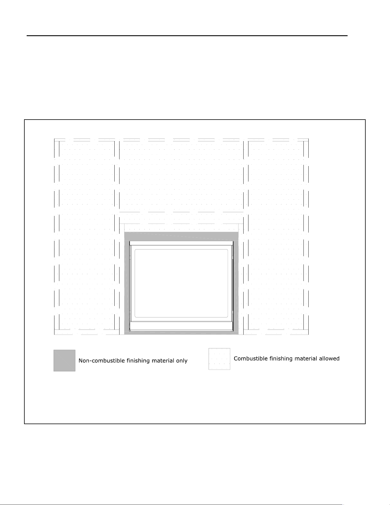
Figure 4.4 - Noncombusble Finishing Material
Note: Shown below is where noncombusble nishing material is allowed. If you want the nishing material to
overlap the front of the replace you are required to use noncombusble nishing material on top of the appli-
ance. Finishing material cannot ow the glass frame assembly, upper hood, and component access panel.
Hussong Mfg. Co, Inc. 25 Rev. 10 - November 2023
SP-34, PFS Report No. 19-553 Starng Serial Number: 23 86710 49
Note: Sidewall clearance of 4-1/2” (114mm) is shown from the side of the replace.
Figure 4.5 - Combusble Sidewall Projecon
Hussong Mfg. Co, Inc. 26 Rev. 10 - November 2023
SP-34, PFS Report No. 19-553 Starng Serial Number: 23 86710 49
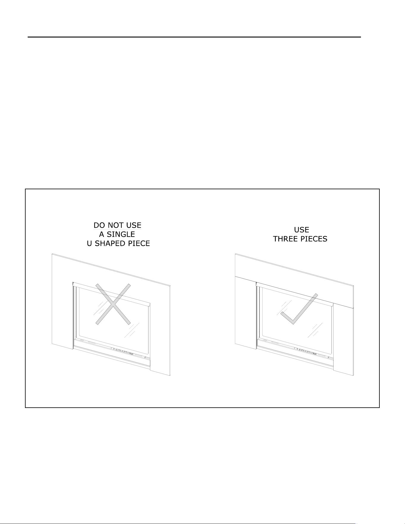
4.1.4 Recommended Installaon of Marble and other stone materials
Kozy Heat recommends the following statements when using marble, granite, or other stone nishing materials
• Never use a one-piece marble, granite or natural stone that is cut in a U-shape for nishing material to cover the
sides and top areas around the replace opening.
• If you use a one piece U-shaped piece of marble, or stone nishing material the material is suscepble to cracking
due to thermal expansion
• Refer to the manufacturer and supplier of your nishing material for use in high heat applicaons like around a re-
place. Ensure the material can be exposed to temperatures greater than 160°F. Kozy Heat does not assume any liabil-
ity for discoloring, cracking, or other heat related damage.
Figure 4.6 - Marble Installaon Example
Hussong Mfg. Co, Inc. 27 Rev. 10 - November 2023
SP-34, PFS Report No. 19-553 Starng Serial Number: 23 86710 49
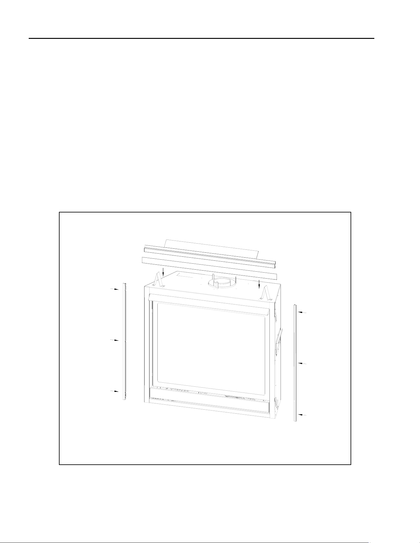
4.2 SP34-081 Exterior Trim Installaon
Exterior Trim Kit (#SP34-081) is an oponal trim kit for this
appliance..
NOTE: The exterior trim kit is recommended to hide the
nishing edge of the facing material when the facing mate-
rial bus up against the appliance.
IMPORTANT: This trim kit assembly must be aached
before replace installaon.
1. Remove and save (2) screws securing the facing mate-
rial stando.
2. Install the top exterior trim piece and the facing mate-
rial stando with the (2) previously removed screws.
3. Remove the (3) screws shown per side and install the
side exterior trim pieces.
Figure 4.7 - Exterior Trim Kit Installaon
Hussong Mfg. Co, Inc. 28 Rev. 10 - November 2023
SP-34, PFS Report No. 19-553 Starng Serial Number: 23 86710 49
4.3 Safety Barrier Installaons
4.3.1 Safety Barrier Screen (#SP34-ES2)
1. Locate the (4) slots located on each side of the replace frame.
2. Align the notched tabs located on the back of the safety screen with the slots on the replace frame.
3. Raise the safety screen front slightly into slots and allow the tabs to lower into posion.
• To remove the safety screen: li the screen up and out of slots.
4.3.2 Overlay Designs (#SP34-POL & #SP34A-POL)
1. If installed, remove the safety barrier screen.
2. Center the overlay over the safety screen.
3. Located the (4) tabs on the overlay. Hand bends the tabs to secure the overlay to the safety screen front.
4. Located the (4) slots located on each side of the replace frame.
5. Align notched tabs located on the back of the safety screen with the slots on the replace frame.
6. Raise the safety barrier slightly into slots and allow the tabs to lower into posion.
• To remove the safety screen: li the screen up and out of slots.
Figure 4.8 - Safety Barrier Installaon
Hussong Mfg. Co, Inc. 29 Rev. 10 - November 2023
SP-34, PFS Report No. 19-553 Starng Serial Number: 23 86710 49
5.0 Gas Line Connecon
5.1 Gas Conversion
SP-34-L: Stepper Motor sold separately to complete gas conversion
ATTENTION: The conversion shall be carried out in accordance with the requirements of the provincial authories having
jurisdicon and in accordance with the requirements of the ANSI Z223.1 installaon code.
This replace is manufactured for use with natural gas. Follow the instrucons included with the conversion kit if con-
verng to propane.
5.2 Gas Line Installaon
CAUTION: Installaon of the gas line must only be done by a qualied person in accordance with local building codes, if
any. If not, follow ANSI 223.1. Commonwealth of Massachuses installaons must be done by a licensed plumber or gas
er.
NOTE: The appliance and its individual shuto valve must be disconnected from the gas supply piping system during any
pressure tesng of that system at pressures in excess of ½ psi (3.5 kPa). For test pressures equal to or less than ½ psi (3.5
kPa), the appliance must be isolated from the gas supply piping system by closing its individual manual shut-o valve.
• A listed (and Commonwealth of Massachuses approved) ½” (13mm) tee handle manual shut-o valve and exible
gas connector are to be connected to the ½”(13mm) control valve inlet. If substung for these components, please
consult local codes for compliance.
• This replace is equipped with a 3/8” (10mm) x 18” (457mm) long exible gas connector and manual shut-o valve.
• Run gas line into replace through gas line hole provided. The gas line should be run to the point of connecon where
the shut-o valve and exible gas line will connect. See Figure 2.1, Appliance Dimensions on page 9 for gas line access.
• Do not run gas line in a manner that would obstruct fan operaon.
• For high altude installaons, consult the local gas distributor or the authority having jurisdicon for proper rang
methods.
Table 5.1, Inlet Gas Supply Pressures - SP-34-L (IPI)
Natural Gas Propane
Minimum Pressure 5” WC (1.25kPa)
7” WC (1.74 kPa)
recommended
11” WC (2.74 kPa)
Maximum Pressure 10” WC (2.49 kPa) 13” WC (3.24 kPa)
Table 5.2, Inlet Gas Supply Pressures - SP-34-MV (Millivolt)
Natural Gas Propane
Minimum Pressure 5” WC (1.25kPa)
7” WC (1.74 kPa)
recommended
11” WC (2.74 kPa)
Maximum Pressure 10” WC (2.49 kPa) 13” WC (3.24 kPa)
Hussong Mfg. Co, Inc. 30 Rev. 10 - November 2023
SP-34, PFS Report No. 19-553 Starng Serial Number: 23 86710 49
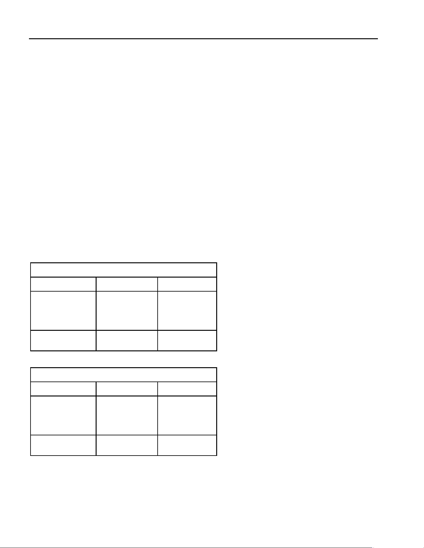
6.1 Vercal Vent Cap Terminaon
Note: Natural Dra Applicaons only.
• Refer to Figure 6.1 below for vercal vent terminaons clearances.
• Refer to Figure 6.2 below for clearance between two vercal terminaons.
6.0 Terminaon Locaons
Figure 6.1 - Vercal Vent Clearances
Figure 6.2 - Clearances Between Two Terminaons
Hussong Mfg. Co, Inc. 31 Rev. 10 - November 2023
SP-34, PFS Report No. 19-553 Starng Serial Number: 23 86710 49
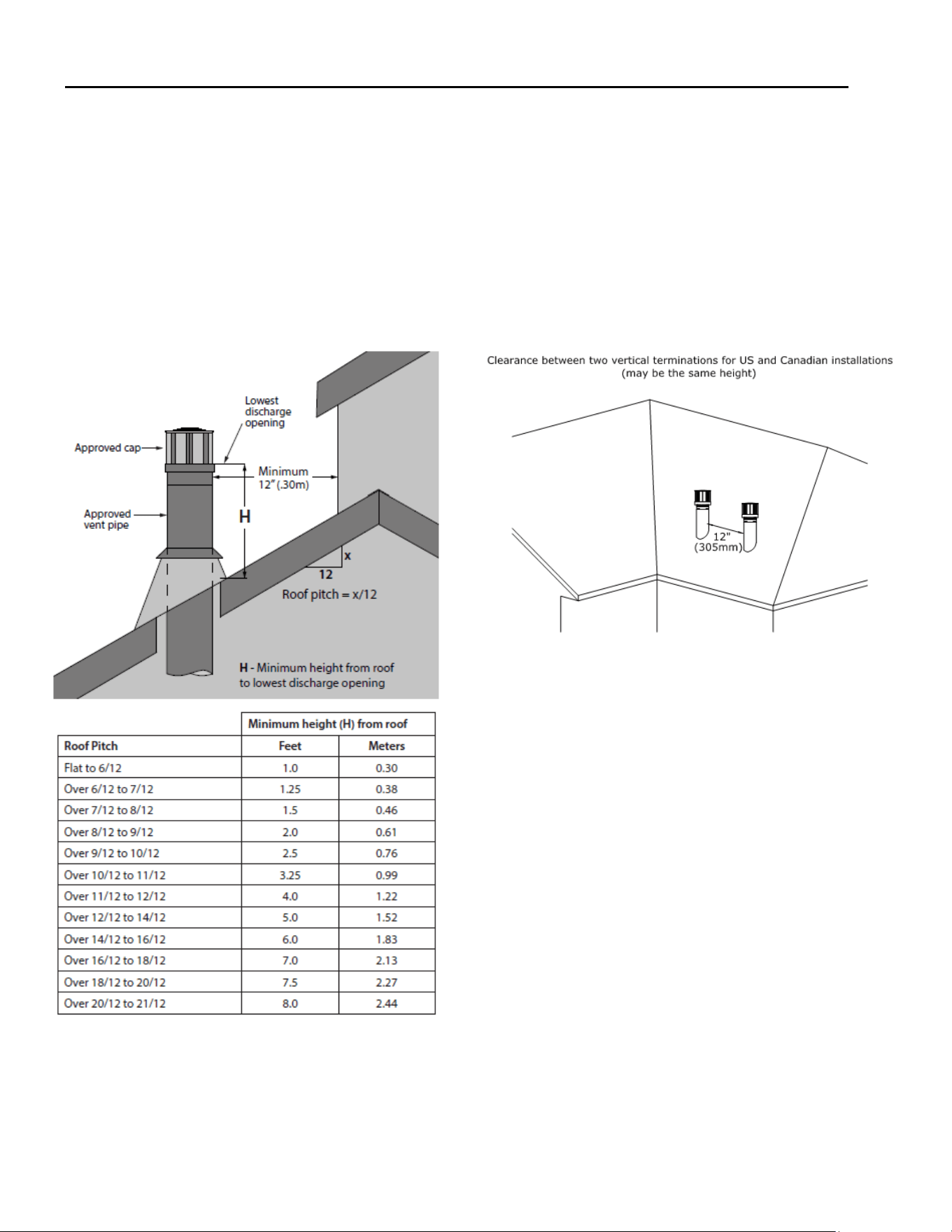
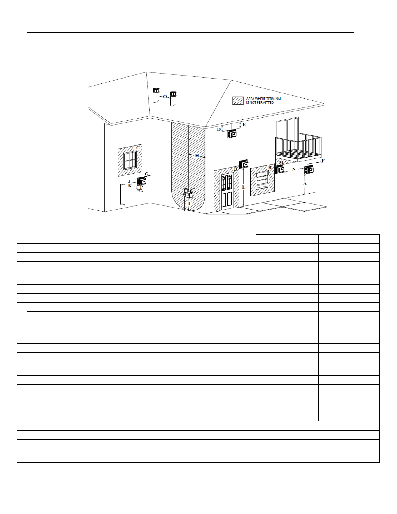
6.2 Minimum Terminaon Clearances
Refer to Figure 6.3 and the table below for natural dra vent terminaon clearance locaons.
Canadian Installaons US Installaons
A Clearance above grade, veranda, porch, desk, or balcony. 12” (30cm) 12” (30cm)
B Clearance to window or door that may be opened 12” (30cm) 9” (23cm)
C Clearance to permanently closed window (recommended to prevent condensaon on window) 12” (30cm)* 12” (30cm)*
D
Vercal clearance to venlated sot located above the terminal within a horizontal distance of 2 feet
(61cm) from the edge of the terminal
24” (61cm)* 24” (61cm)*
E Clearance to unvenlated sot 12” (30cm)* 12” (30cm)*
F Clearance to outside corner 0” (0cm)* 0” (0cm)*
G Clearance to inside corner 12” (30cm)* 12” (30cm)
H
Clearance to each side of center line extended above meter/regulator assembly 3’ (91cm) within a height
15’ (4.5m) above the
meter/regulator assembly
*
I Clearance to service regulator vent outlet 3’ (91cm) *
J Clearance to non-mechanical air supply inlet to building or the combuson air inlet to any other appliance 12” (30cm) 9” (23cm)
K Clearance to mechanical air supply inlet 6’ (1.83m)
3’ (91cm) above
[Massachuses: 10’ (3m)
above] if within 10’ (3m)
horizontally
L Clearance above paved sidewalk or paved driveway located on public property 7’ (2.13m)† *
M Clearance under veranda, porch deck, or balcony 12” (30cm)‡ 12” (30cm)
N Clearance between two horizontal terminaons 12” (30cm) 12” (30cm)
O Clearance between two vercal terminaons (may be same height) 12” (30cm) 12” (30cm)
P Above furnace exhaust or inlet 12” (30cm) 12” (30cm)
* Clearance in accordance with local installaon codes and the requirements of the gas supplier
†A vent shall not terminate directly above a sidewalk or paved driveway that is located between two single family dwellings and serves both dwellings.
‡ Permied only if veranda, porch, desk, or balcony is fully open on a minimum of two sides beneath the oor
VINYL SOFFIT, VINYL CEILING, AND VINYL OVERHANG DISCLAIMER: Clearances to heat resistant material (i.e. wood, metal). This does not include vinyl. Hussong Manufac-
turing Co., Inc. will not be held responsible for heat damage caused from terminang under vinyl overhangs, vinyl ceilings, or vinyl venlated/unvenlated sots.
Figure 6.3 - Terminaon Clearances
Hussong Mfg. Co, Inc. 32 Rev. 10 - November 2023
SP-34, PFS Report No. 19-553 Starng Serial Number: 23 86710 49
7.0 Venng
7.1 Approved Vent Systems
This appliance is equipped for use with a 4” (102mm) exhaust by 6-5/8” (168mm) air intake co-axial vent pipe system.
This appliance is approved for use with manufacturers (horizontal and vercal terminaons): American Metal Products (Ameri
-Vent), BDM, ICC, Metal Fab*, Olympia Chimney Supply, Inc., Selkirk, and Simpson DuraVent. See secons 7.1.1.
This appliance can be adapted to use 4” diameter aluminum exible pipe by any listed vent manufacturer when used in com-
binaon with an exisng minimum 7” ID Class A metal/masonry chimney. Refer to secon 7.6 for more informaon.
This appliance can be adapted from co-axial to co-linear vent system. Refer to secon 7.7 for more informaon.
This appliance is approved for use with Kozy Heat 4” x 7” #700-2 series Flexible Direct Vent System (horizontal terminaon
only). Refer to Secon 7.8 for venng components and installaon instrucons.
Refer to the vent manufacturer’s installaon manual for complete installaon instrucons. Installaon must conform with the
requirements and restricons specied in this manual.
7.1.1 Approved 4” x 6-5/8” Vent Systems
Table 7.1, Approved 4” x 6-5/8” Vent Systems
Vent Manufacturer Vent Cap Part Number
American Metal Products
(Ameri-Vent)
4DHCS
4DHC
4DVC
4D14S
4D36S
DVCC33
BDM 940033HWS
940033
DVR6-HC
DVR6-HCP
DVR6-VCLP
DVR-VCH
DVR6-SNK14
DVR6-SNK36
Simpson DuraVent 46DVA-CL33H
46DVA-CL33P
46DVA-HSCH
46DVA-VCH
46DVA-VC
46DVA-VCE
46DVA-HTC
ICC CT3
IVT
TM-4VTA
TM-4HT
TM-4RHT
TM-4DHT
TM-4SVT
TM-4ST14
TM-4ST36
Table 7.1 connued, Approved 4” x 6-5/8” Vent Systems
Vent Manufacturer Vent Cap Part Number
Kozy Heat 745-2
718-2
Metal Fab
(Adapter 4DDA must be used)
4DVT33F
4DHT
4DVT
4DVTHW
4DST14
4DST36
Olympia Chimney Supply, Inc. VDV-HC04
VDV-VC04
VDV-VCH04
VDV-SNC0414
VDV-SNC0436
VDV-RCL33
VDV-CC33
VDV-VCCH33
Selkirk 4DT-HC
4DT-HCR
4DT-VT
4DT-VC
4DT-ST14
4DT-ST36
4DT-CC33
Hussong Mfg. Co, Inc. 33 Rev. 10 - November 2023
SP-34, PFS Report No. 19-553 Starng Serial Number: 23 86710 49
7.2 Venng Requirements
NOTE: Consult the local and naonal installaon codes to
assure adequate combuson and venlaon air is availa-
ble. Venng requirements apply to both natural gas and
propane.
• Flame height and appearance will vary depending
upon venng conguraon and the type of fuel used.
• Provide a means for visually checking the vent con-
necon to the appliance aer the replace is in-
stalled.
• A minimum of 1” (25mm) clearance on all sides of the
vercal vent pipe must be maintained. Ac insulaon
shields may be insulated using unfaced insulaon
products listed as noncombusble per ASTM E 136.
• A minimum of 1” (25mm) clearance on the top, sides,
and boom of the horizontal vent pipe must be main-
tained. Wall thimble products that comply with the
required clearances to combusbles must be installed
for all horizontal vent runs that pass through interior
or exterior walls. These wall thimble products may be
insulated using unfaced insulaon products listed as
noncombusble per ASTM E 136.
• The provided vent heat shield is required to be in-
stalled in all venng scenarios. See Figure 7.1, 7.2, and
7.3. The stand o assembly and heat shields are cut
away in this image to show the vent heat shield
beer.
• The gas appliance cannot be connected to a chimney
ue that is serving a separate solid-fuel burning appli-
ance.
• Horizontal vent secons require at least 1/4” (6mm)
rise for every 12” (305mm) of travel.
Figure 7.1 - Vent Heat Shield Installaon
Figure 7.2 - Vent Heat Shield Installaon
Figure 7.3 - Vent Heat Shield Installaon
Hussong Mfg. Co, Inc. 34 Rev. 10 - November 2023
SP-34, PFS Report No. 19-553 Starng Serial Number: 23 86710 49
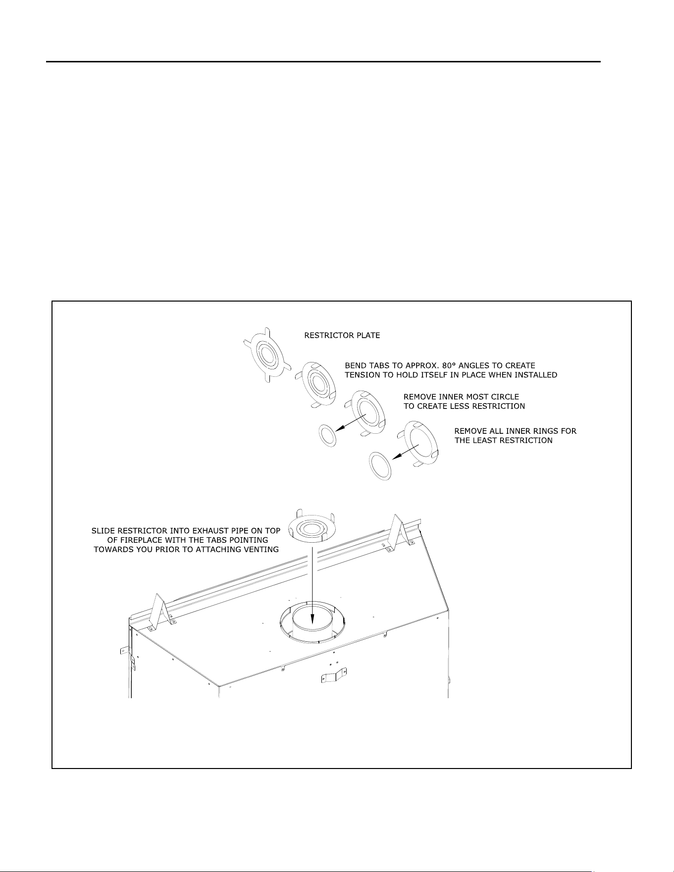
7.3 Vent Restricon
• Burner ame appearance and characteriscs are aect-
ed by altude, fuel quality, venng conguraon, and
other factors. To achieve desirable ame appearance,
the vent exhaust may be restricted by the restrictor
plate (included in components packet).
• The restrictor plate is shipped with all inner rings intact,
and when installed, provides the most vent restricon.
There are (2) inner rings that can be knocked out. As
you knock out and remove an inner ring you have less
vent restricon where removing both inner rings you
will have the least amount of vent restricon.
• Follow FIGURE 7.4 for restrictor plate installaon before
aaching venng or through the bae if venng is al-
ready aached. For vent restricon plate recommenda-
ons and adjustments, see secon 12.3.3, Vent Re-
stricon (aer installaon).
Figure 7.4 - Restrictor Installaon
7.4 Use of Flexible Venng Outside the
Appliance Enclosure
• If an approved venng manufacturer oers exible
venng opons that can replace rigid vent pipe follow
the vent manufacturer's instrucons.
• Flexible vent pipe can only be used outside of the appli-
ance enclosure.
• Excepon: SP34 is approved for #700-2 Series Hori-
zontal Flex Vent Terminaon Kit. This is a horizontal
vent terminaon kit that would be inside the re-
place enclosure. See Secon 7.8.
• Flexible vent pipe cannot be used to terminate the vent
system vercally. Only approved ex systems are ap-
proved for horizontal terminaon (#700-2).
Hussong Mfg. Co, Inc. 35 Rev. 10 - November 2023
SP-34, PFS Report No. 19-553 Starng Serial Number: 23 86710 49
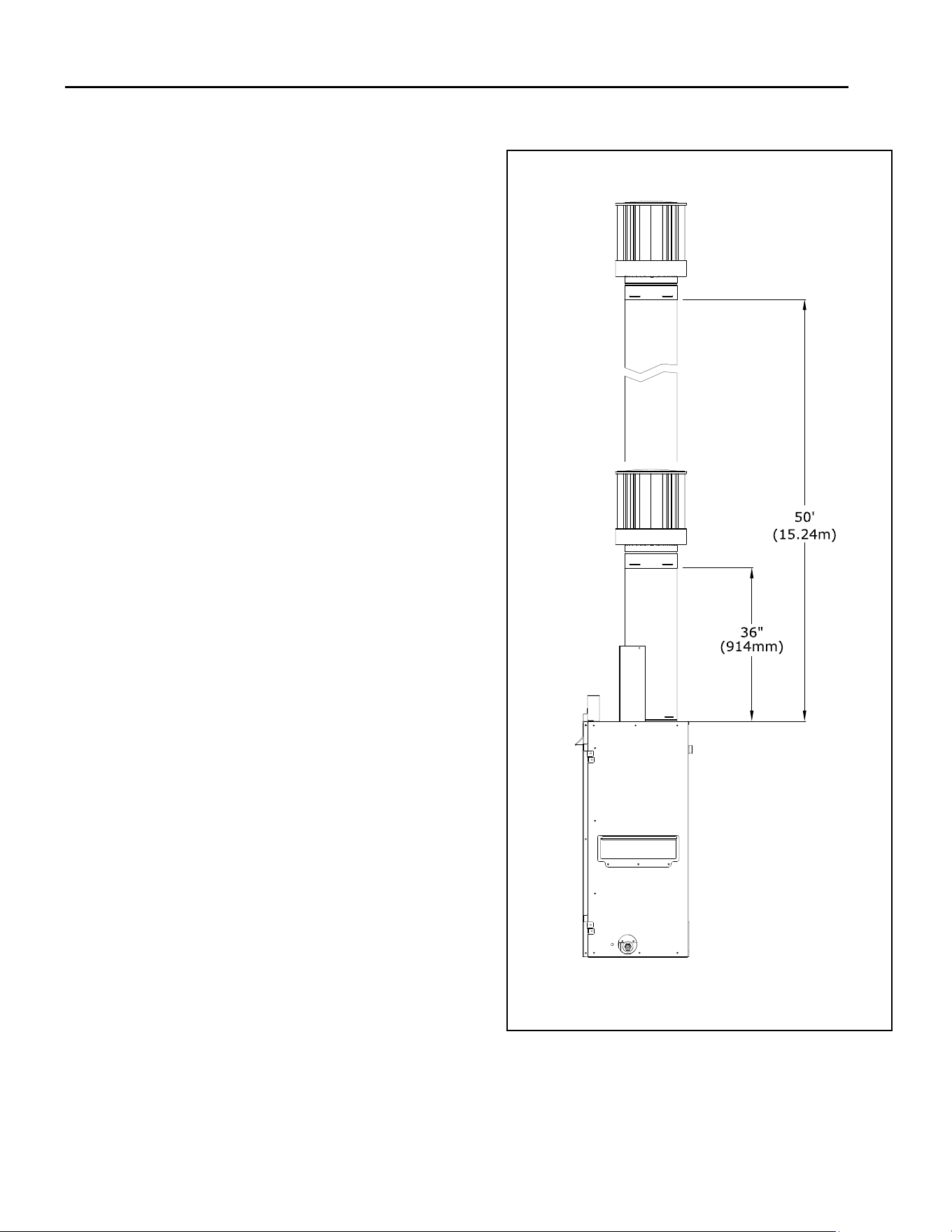
7.5 Natural Dra Co-Axial Pipe Installaons
7.5.1 Vercal Terminaons
Note: Natural Gas and Propane Installaons
(i) Minimum / Maximum Vercal Terminaons:
3’ (914mm) minimum vercal length / 50’ (15.24m)
maximum vercal length + terminaon cap
Figure 7.5 - Vercal 4”x6-5/8” Vent Pipe
Hussong Mfg. Co, Inc. 36 Rev. 10 - November 2023
SP-34, PFS Report No. 19-553 Starng Serial Number: 23 86710 49
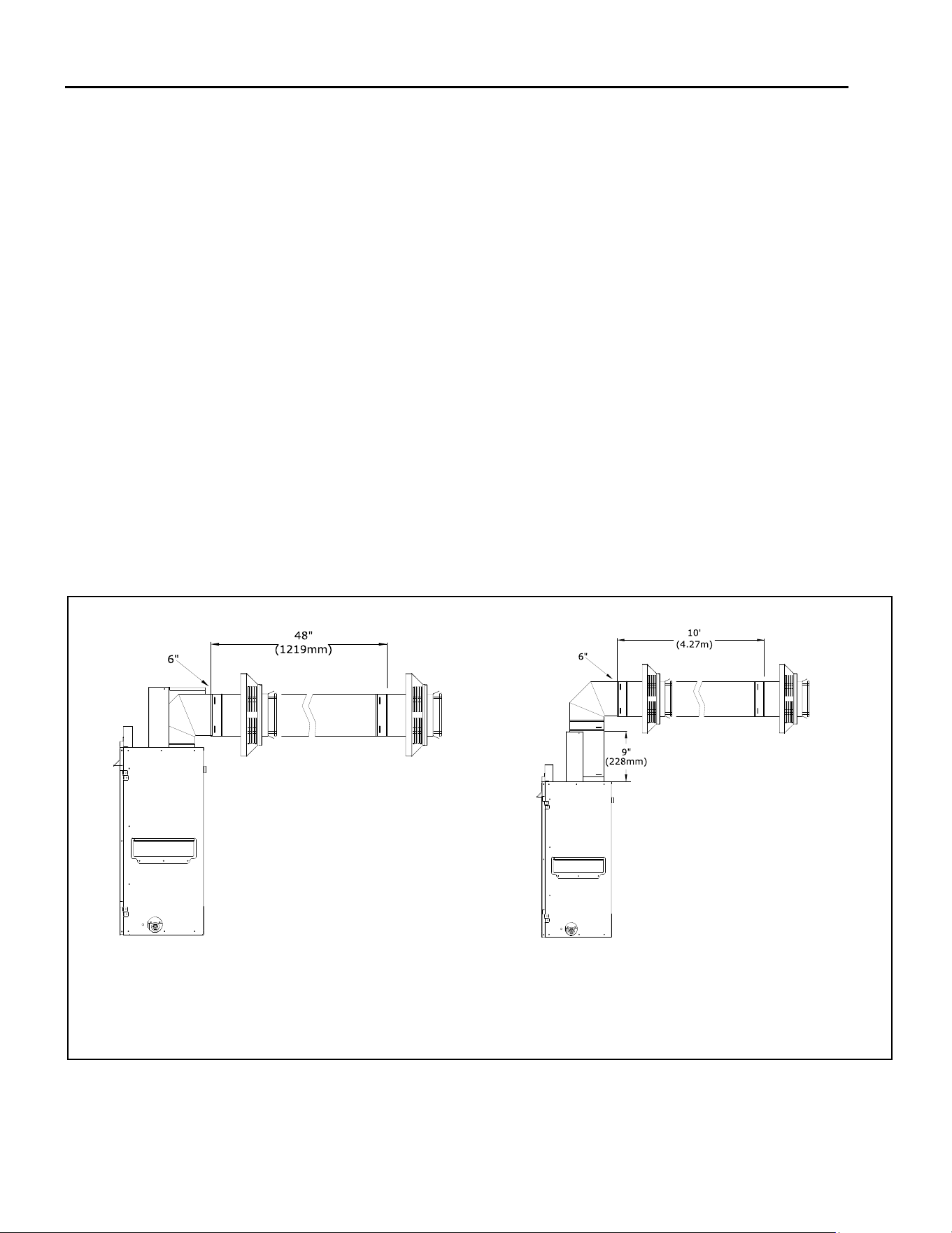
7.5.2 Horizontal Terminaons
Note: Natural Gas and Propane Installaons
Note: Figures shown in this secon use rigid pipe. Venng
requirements also apply to Secon 7.8 #700-2 Flex Vent.
IMPORTANT: Horizontal vent secons require 1/4” (6mm) of
rise for every 12” (305mm) of travel.
(i) Minimum 0” Vercal Vent Pipe/ Minimum Horizontal:
0” (0mm) vercal vent pipe + 90° horizontal elbow +
6” (152mm) minimum horizontal vent pipe + termina-
on cap
(i) Minimum 0” Vercal Vent Pipe / Maximum Horizontal:
0” (0mm) vercal vent pipe + 90° horizontal elbow +
48” (1219mm) maximum horizontal vent pipe + termi-
naon cap
(ii) Minimum 9” Vercal Vent Pipe / Minimum Horizontal:
9” (228mm) vercal vent pipe + 90° horizontal elbow +
6” (152mm) minimum horizontal vent pipe + termina-
on cap
(ii) Minimum 9” Vercal Vent Pipe / Maximum Horizontal:
9” (228mm) vercal vent pipe + 90° horizontal elbow +
10’ (3m) maximum horizontal vent pipe + terminaon
cap
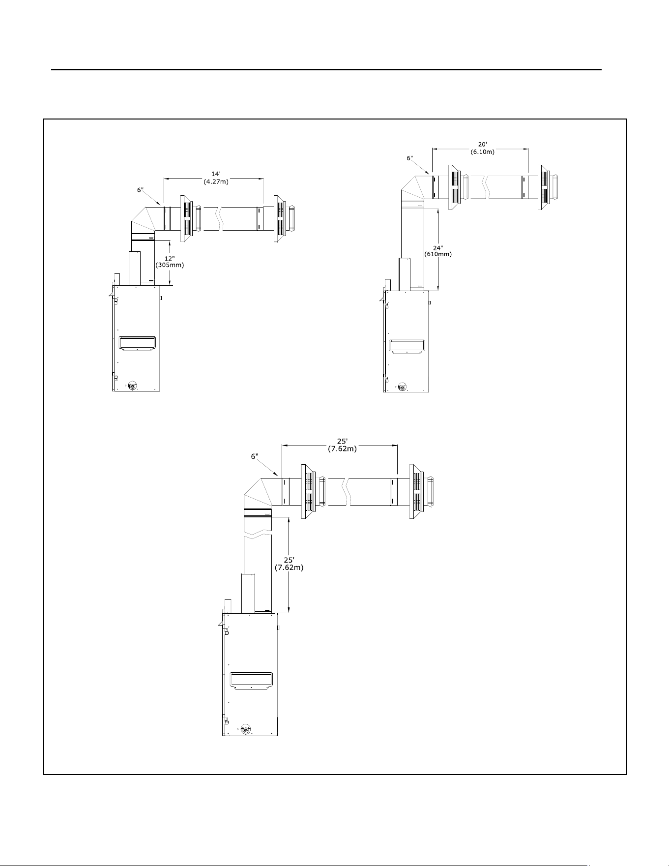
(iii) Minimum 12” Vercal Vent Pipe / Minimum Horizontal:
12” (305mm) vercal vent pipe + 90° horizontal elbow +
6” (152mm) minimum horizontal vent pipe + terminaon
cap
(iii) Minimum 12” Vercal Vent Pipe / Maximum Horizontal:
12” (305mm) vercal vent pipe + 90° horizontal elbow +
14’ (4.27m) maximum horizontal + terminaon cap
(iv) Maximum 24” Vercal / Minimum Horizontal:
24” (609mm) maximum vercal vent length + 90° horizontal
elbow + 6” (152mm) horizontal vent pipe + terminaon cap
(iv) Maximum 24” Vercal / Maximum Horizontal:
24” (609mm) maximum vercal + 90° horizontal elbow +
20’ (6m) maximum horizontal + terminaon cap
(v) Maximum 25’ Vercal / Minimum Horizontal:
25’ (7.62m) maximum vercal vent length + 90° horizontal
elbow + 6” (152mm) horizontal vent pipe + terminaon cap
(v) Maximum 25’ Vercal / Maximum Horizontal:
25’ (7.62m) maximum vercal + 90° horizontal elbow +
25’ (7.62m) maximum horizontal + terminaon cap
Figure 7.6 - Horizontal 4”x 6-5/8” Vent Pipe
Hussong Mfg. Co, Inc. 37 Rev. 10 - November 2023
SP-34, PFS Report No. 19-553 Starng Serial Number: 23 86710 49
Figure 7.7 - Horizontal 4”x 6-5/8” Vent Pipe
Hussong Mfg. Co, Inc. 38 Rev. 10 - November 2023
SP-34, PFS Report No. 19-553 Starng Serial Number: 23 86710 49
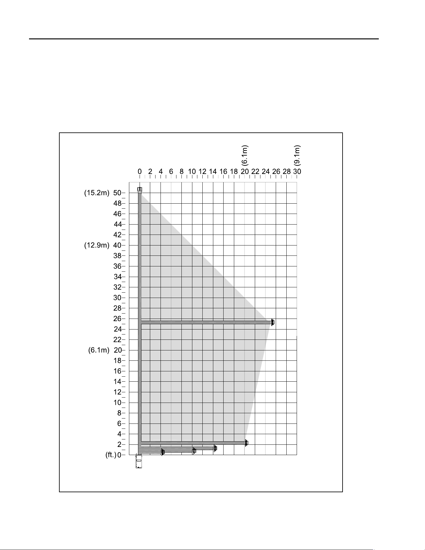
7.5.3 Combinaon Venng
Note: Natural Gas and Propane Installaons
Vent terminaon must be within the shaded area in
FIGURE 7.8.
The vercal vent heat shield must be installed for every
vent conguraon.
• 25’ (7.62m) maximum vercal rise + 25’ (7.62m) maxi-
mum horizontal run = 50’ (15.2m) of total length
• Maximum of (5) 90° elbows. For each addional 90° el-
bow used aer the rst elbow, 3’ (914mm) must be sub-
tracted from maximum venng allowed.
• (2) 45° degree elbows may be used in place of (1) 90°
elbow. For each 45° elbow used, 18” (457mm) must be
subtracted from maximum venng allowed.
Figure 7.8 - Combinaon 4”x 6-5/8” Vent Pipe Chart
Hussong Mfg. Co, Inc. 39 Rev. 10 - November 2023
SP-34, PFS Report No. 19-553 Starng Serial Number: 23 86710 49
7.6 Class A Chimney / Masonry Chimney
Conversion
This appliance is approved to be adapted for Class A/
Masonry Chimney conversion with kits ulizing a
4” (102mm) exible exhaust by any vent manufactur-
ers listed in secon 7.1, APPROVED VENT SYSTEMS.
Before conversion, have the exisng installaon
inspected by a qualied chimney sweep or profes-
sional installer. The exisng chimney system must be
in serviceable condion, and funconally sound.
Before proceeding with following installaons, check
with local building jurisdicon to verify this type of
installaon is allowed in your area.
Follow Figure 7.9 for allowable venng congura-
ons for installaon in exisng through-the-ceiling,
Class A/Masonry chimney. Route the exhaust gases
and intake air through the exisng Class A/Masonry
chimney.
The gas appliance cannot be connected to a chimney
ue that is serving a separate solid-fuel burning ap-
pliance.
7.6.1 4” Flex Pipe Venng Conguraons
IMPORTANT: Horizontal vent secons require at least
1/4” (6mm) rise for every 12” (305mm) of travel.
IMPORTANT: The vent heat shield assembly must be
installed when incorporang minimum horizontal
venng o the top of the appliance.
IMPORTANT: Care should be taken when installing
exible pipe to avoid a ght bend that may cause
abrasion or damage to the exible pipe.
The vent opon listed below allow for a minimum of
0” (0mm) to a maximum of 24” (610mm) horizontal
run using rigid or exible pipe.
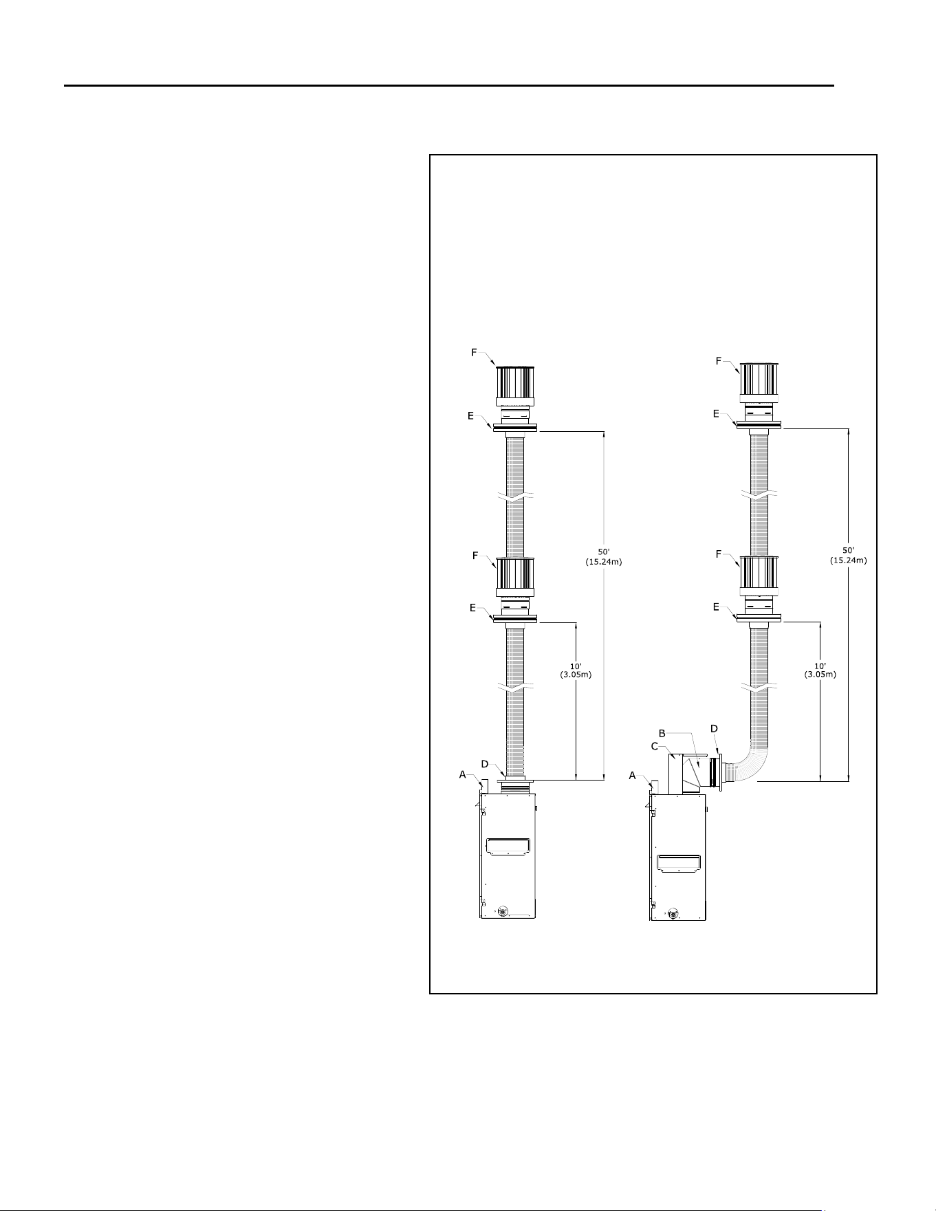
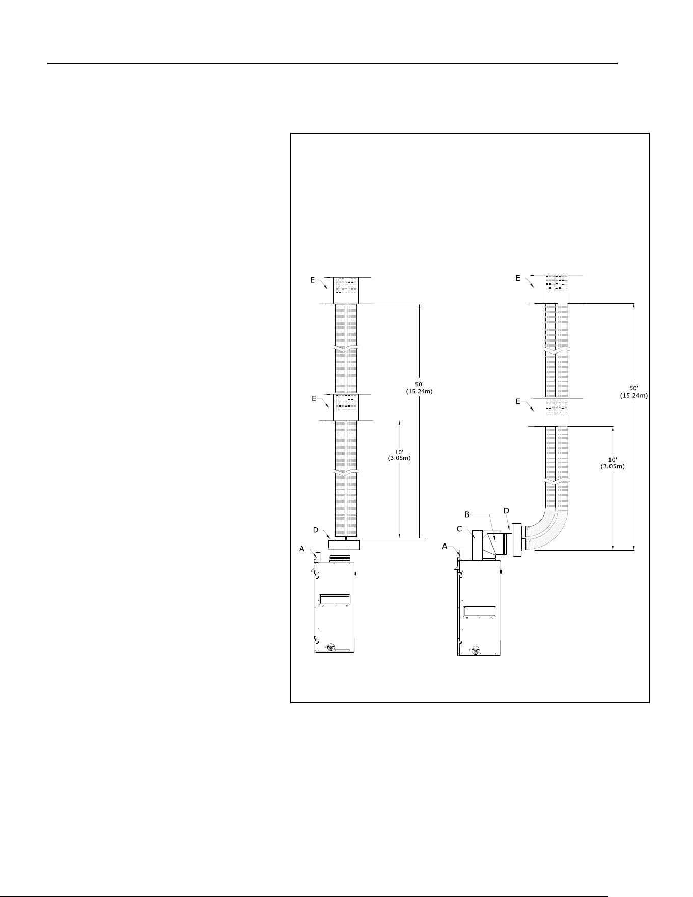
(1) Minimum / Maximum Vercal Terminaons
Retro connector + 10’ (3.05m) minimum length
of 4” aluminum exible pipe / 50’ (15.24m) max-
imum length of 4” aluminum exible pipe + top
adapter + terminaon cap
(2) Minimum / Maximum Vercal Terminaons
using a 90° elbow
4” x 6-5/8” 90° elbow + retro connector +
10’ (3.05m) minimum length of 4” aluminum
exible pipe / 50’ (15.24m) maximum length of
4” aluminum exible pipe + top adapter +
terminaon cap
Figure 7.9 - Class A Chimney / Masonry Chimney
A. Header Stand-o
B. 90° Elbow
C. Vercal Vent Heat Shield
D. Retro Connector
E. Top Adapter
F. Terminaon Cap
Hussong Mfg. Co, Inc. 40 Rev. 10 - November 2023
SP-34, PFS Report No. 19-553 Starng Serial Number: 23 86710 49
7.7 Co-Axial to Co-Linear Chimney
Conversion
Before conversion, have the exisng installa-
on inspected by a qualied chimney sweep
or professional installer. The exisng chim-
ney system must be in serviceable condion,
and funconally sound. Before proceeding
with following installaons, check with local
building jurisdicon to verify this type of
installaon is allowed in your area.
Follow Figure 7.10 for allowable venng
conguraons for installaon in exisng
masonry chimney. Route the exhaust gases
and intake air through the exisng masonry
chimney.
7.7.1 Co-axial to Co-Linear Venng
Conguraons
IMPORTANT: Horizontal vent secons re-
quire at least 1/4” (6mm) rise for every
12” (305mm) of travel.
IMPORTANT: Care should be taken when
installing exible pipe to avoid a ght bend
that may cause abrasion or damage to the
exible pipe.
IMPORTANT: The vent heat shield assembly
must be installed when incorporang mini-
mum horizontal venng o the top of the
appliance.
The vent opon listed below allows for a
minimum of 0” (0mm) to a maximum of
24” (610mm) horizontal run using rigid or
exible pipe.
1. Minimum / Maximum Vercal
Terminaons
Coaxial to Co-linear adapter +
10’ (3.05m) minimum length of 3” alu-
minum exible pipe / 50’ (15.24m) max-
imum length of 3” x 3” aluminum exi-
ble pipe + terminaon cap
2. Minimum / Maximum Vercal
Terminaons
90° horizontal elbow + Coaxial to Co-
linear adapter + 10’ (3.05m) minimum
length of 3” aluminum exible pipe /
50’ (15.24m) maximum length of 3” x 3”
aluminum exible pipe + terminaon
cap
Figure 7.10 - Co-Axial to Co-Linear Venng
A. Header Stand-o
B. 90° Elbow
C. Vercal Vent Heat Shield
D. Co-Axial to Co-Linear Adapter
E. Terminaon Cap
Hussong Mfg. Co, Inc. 41 Rev. 10 - November 2023
SP-34, PFS Report No. 19-553 Starng Serial Number: 23 86710 49
7.8 #700-2 Series Horizontal Flex Vent Terminaon Kit
IMPORTANT: The ex pipe is permanently aached to the exterior plate. DO NOT ATTACH either #745-2 or #718-2 termina-
on kit to replace (or extension kit) unl it has been passed through the framed opening. Install terminaon plates to the
outside wall exterior.
IMPORTANT: The minimum bend radius to center is 6” (152mm) required for installaon of the exible vent pipe. Care
should be taken when installing to avoid a ght bend that may cause abrasion or damage to the exible pipe.
The vercal vent heat shield must be installed. See Secon 7.2.
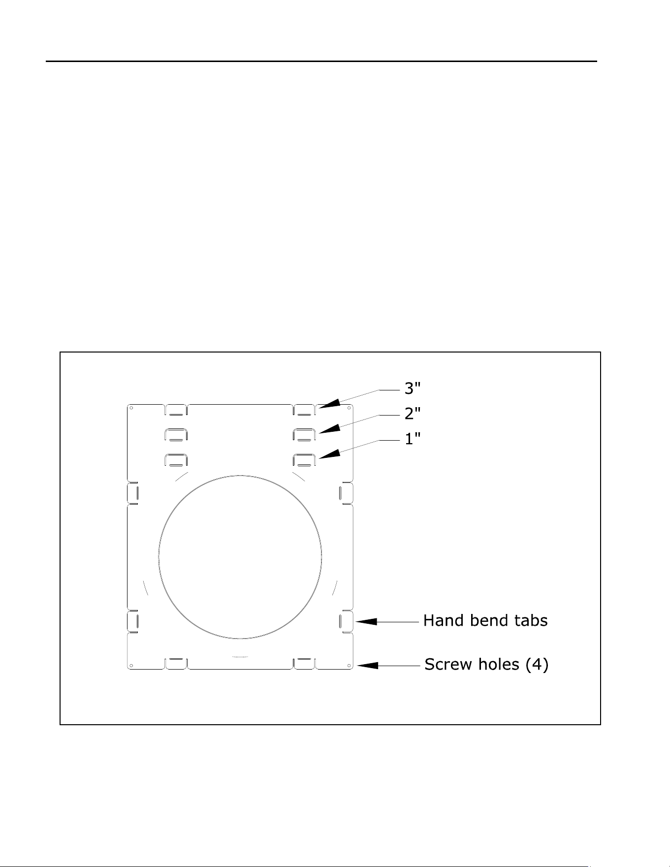
7.8.1 700-WPT Installaon Instrucons
IMPORTANT: The heat shield within the wall thimble must overlap a minimum of 1-1/2” (38mm). An extension will be need-
ed if going through a thicker wall than 6-1/2” (165mm). Refer to BDM vent manufacturer if wall extension is necessary.
Hand bend the (2) tabs on the top of the wall pass through at the 1” (25mm) top clearance. Hand bend the (6) tabs on
the sides and boom of the wall pass through. Repeat for other secon.
From the interior, install one secon of the wall pass through. Secure with (4) screws (not provided).
From the exterior, install the other secon of the wall pass through, overlapping the heat shields as necessary to accom-
modate wall thickness. The secon must overlap a minimum of 1-1/2” (38mm). Secure to exterior wall with (4) screws
(not provided).
Follow vent manufacturer installaon instrucons for vent installaon.
Figure 7.11 - WPT
Hussong Mfg. Co, Inc. 42 Rev. 10 - November 2023
SP-34, PFS Report No. 19-553 Starng Serial Number: 23 86710 49
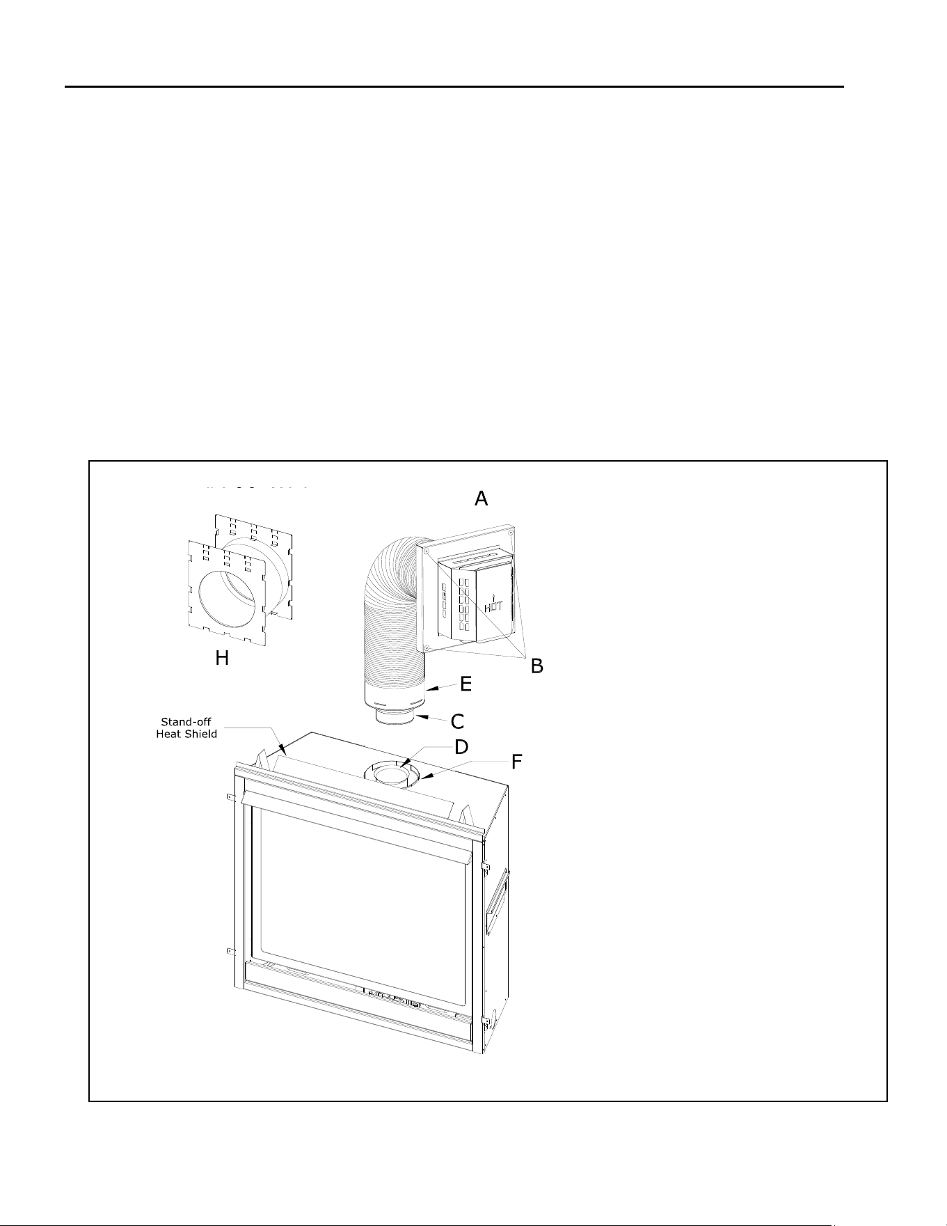
7.8.2 700-2 Series Flex Vent Installaon
Aach vinyl siding protector (G) (not shown).
Mount the required wall thimble (H) with 1” (25mm)
top and side clearances as referenced in Secon 8.8.1.
It is oponal to insulated the wall thimble with any
unfaced insulaon products listed as non-combusble
per ASTM E 136.
Apply a liberal bead of exterior sealant around the
outer edge od the terminaon box (A). Place assem-
bly though the wall-pass through in exterior wall, and
secure with (4) screws through the four holes (B).
Form the 4” & 7” exible aluminum pipes on the ter-
minaon kit (#745-2), and if applicable, on each ex-
tension kit (#718-2).
5. Gently pull 4” & 7” pipes down to the top of the re-
place, or if applicable, the extension kit. IM-
PORTANT: DO NOT stretch extension kit beyond
6’ (1.83m); DO NOT stretch beyond what is required
as it is very dicult to decompress ex pipes once
stretched.
6. Place a bead of sealant outside 4” ex pipe collar (C)
(the end with external lip) and sliding the collar into
the 4” pipe on the extension kit or on the top of the
replace (D). Secure with (3) evenly spaced screws.
7. Place a bead of sealant inside the 7” ex pipe collar
(E) (the end with the internal lip), and sliding the col-
lar over 7” pipe on the extension kit or on the top of
the replace (F). Secure with (3) evenly spaced
screws.
If addional extension kits are required, repeat steps 4
and 5, placing 4” & 7” pipes onto previous extension kit.
A. Terminaon Box
B. (4) Holes in exterior wall plate
C. 4” ex pipe collar
D. 4” pipe on the replace
E. 7” ex pipe collar
F. 7” pipe on the replace
G. Vinyl siding protector (not shown)
H. Wall Thimble
Figure 7.12 - #700-2 Flex Kit
Hussong Mfg. Co, Inc. 43 Rev. 10 - November 2023
SP-34, PFS Report No. 19-553 Starng Serial Number: 23 86710 49
8.0 Fireplace Setup
8.1 Glass Frame Assembly
WARNING: Do not operate this replace with the
glass removed, cracked, or broken. Replacement of
the glass assembly, should be done by a licensed or
qualied service person.
8.1.1 Remove Glass Frame Assembly
WARNING: Do not remove the glass assembly when
hot.
1. Remove safety barrier..
2. Locate (2) spring-loaded latches securing the
glass assembly at the boom of the rebox.
3. Pull the spring-loaded latches out and down to
release the boom of the glass assembly.
4. Li glass assembly up and o of the (2) tabs
located at the top of the rebox.
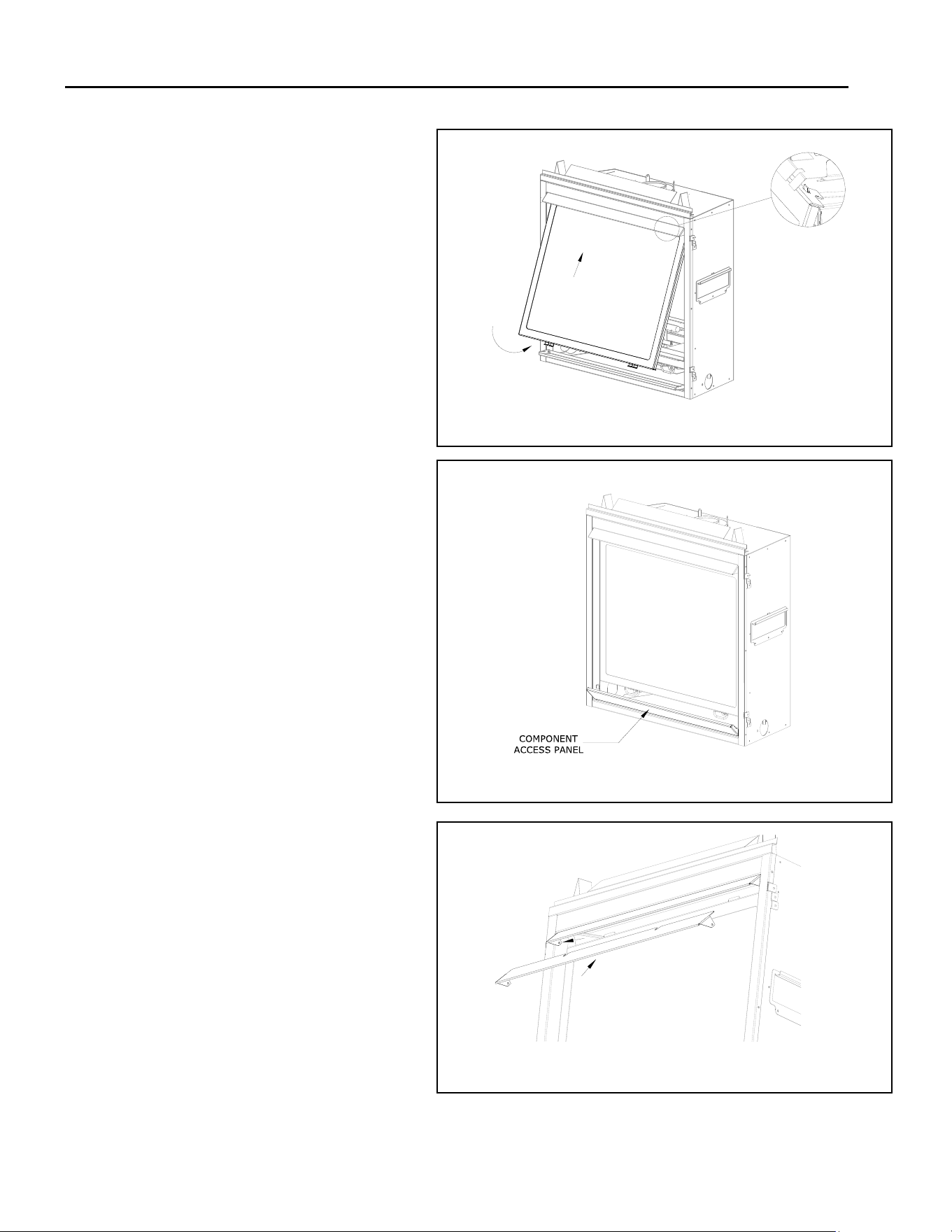
8.1.2 Install Glass Frame Assembly
1. Tilt the top of the glass frame assembly as
shown in Figure 9.1. Align the slots on top of
the glass assembly over the tabs at the top of
the rebox while lowering the boom of the
glass assembly into posion.
2. Pull the spring-loaded latches out and up to
secure the boom of glass to the boom of the
replace.
3. Reinstall safety barrier.
8.2 Component Access Panel Locaon
To access the control module housing, the access
panel will need to be opened. The access panel is
held vercally in place by a magnet at the top
1. Locate component access panel under the
safety screen barrier.
2. Pull on the top of the access panel to open.
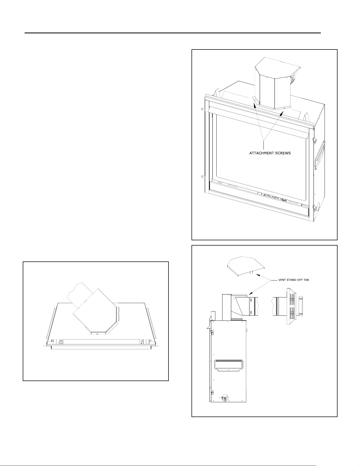
8.3 Hood Installaon
Installaon of the upper hood is required.
1. Locate the (2) clips above the glass frame as-
sembly.
2. Push the hood so it slides into the (2) clips.
Figure 8.2 - Component Access Panel
Figure 8.1 - Glass Frame Installaon
Figure 8.3 - Hood Installaon

Hussong Mfg. Co, Inc. 44 Rev. 10 - November 2023
SP-34, PFS Report No. 19-553 Starng Serial Number: 23 86710 49
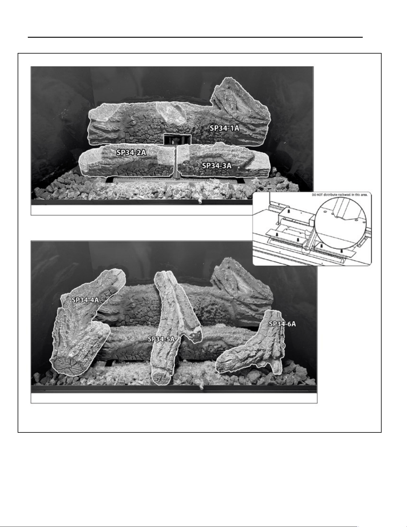
8.4 #SP34-50A Log Set Installaon
NOTE: Log numbers are located on the boom or side of each log. Refer to the following instrucons and illustraon for proper
placement. Your components may look dierent than the ones shown.
CAUTION: Do not place logs directly over burner port holes. Improper log placement may aect ame appearance and may cause
excessive soot to build upon the glass.
• If converng to propane, complete the conversion before installing the log set. Follow the conversion instrucons included
with the kit.
• If installing a panel set, complete installaon of panel set before log installaon
1. Remove valance from replace.
2. Place log SP34-1A on the back log plate.
3. Align the holes in log SP34-2A with the mounng pins on the le front log plate. Push log down to seat.
4. Align the holes in log SP34-3A with the mounng pins on the right front log plate. Push log down to seat.
5. Distribute lava rock in front of the burner. Do not block burner ports or air spaces.
6. Align log SP34-4A with the notches in logs SP34-1A and SP34-2A.
7. Align log SP34-5A with the notches in logs SP34-1A and SP34-2A.
8. Align log SP34-6A with the notches in logs SP34-3A.
9. Distribute rockwool embers onto logs and burner using a s bristle brush. DO NOT block the area as shown below.
Hussong Mfg. Co, Inc. 45 Rev. 10 - November 2023
SP-34, PFS Report No. 19-553 Starng Serial Number: 23 86710 49
Figure 8.4 - Log Set
Hussong Mfg. Co, Inc. 46 Rev. 10 - November 2023
SP-34, PFS Report No. 19-553 Starng Serial Number: 23 86710 49
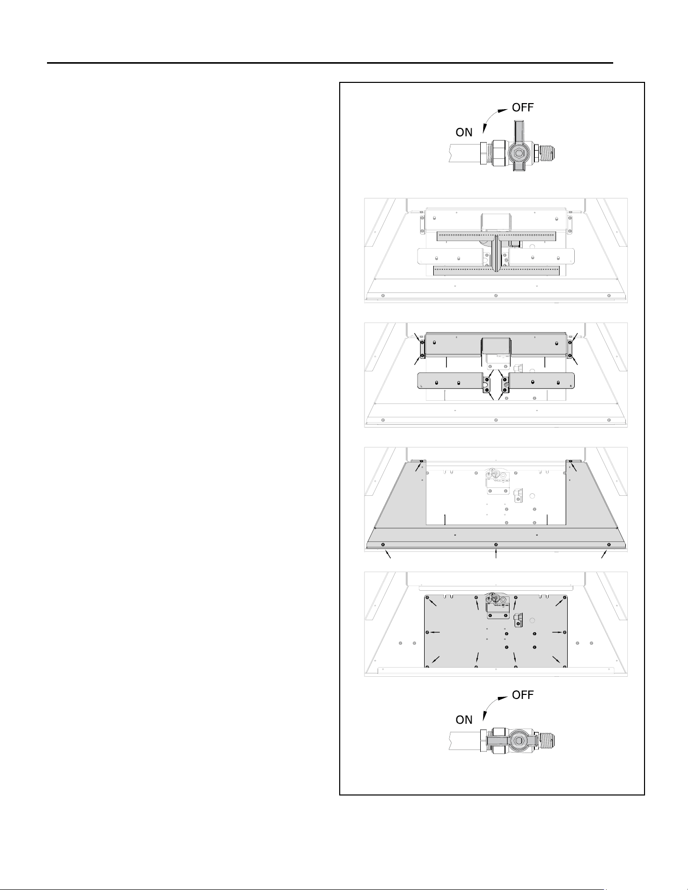
8.5 Control Board Removal and Installaon
WARNING: If burner and/or pilot have been burning,
use appropriate protecon to avoid burns or damage
to personal property before removing any compo-
nents.
DO NOT OPERATE THIS APPLIANCE WITHOUT THE
SEALING GASKET (LOCATED UNDER THE CONTROL
BOARD) IN PLACE. IF GASKETING IS DAMAGED, IT
MUST BE REPLACED.
CAUTION: Check all connecons for leaks with soapy
water, whether eld or factory made.
8.5.1 Control Board Removal
1. Disconnect electrical power. Locate the main shut
-o valve upstream of the appliance connector
and close valve.
2. Open the component access panel.
3. Remove the safety barrier and glass frame assem-
bly.
4. On MV models disconnect any oponal thermo-
stat or controls from the top and boom termi-
nals on the gas valve. On IPI models unplug all
components from the electrical receptable and
disconnect all wiring harnesses aached to the
gas valve.
5. Remove log set, lava rock, and panels (if installed).
6. Remove the burner tube by sliding it to the le o
the burner orice.
7. Remove pilot shield.
8. Remove and save (4) screws securing the back log
plate.
9. Remove and save (4) screws securing the le and
right front log plates.
10. Remove and save (5) screws securing the heat
shield.
11. Remove and save (10) screws securing control
board to rebox oor.
12. Li the control board out of the rebox, being
careful not to damage the sealing gasket under-
neath.
Figure 8.5 - Control Board Removal

Hussong Mfg. Co, Inc. 47 Rev. 10 - November 2023
SP-34, PFS Report No. 19-553 Starng Serial Number: 23 86710 49
8.5.2 Control Board Installaon
1. Place control board in the rebox, aligning the holes
in the control board with the holes in the rebox
boom. VERIFY SEALING GASKET IS IN PLACE.
2. Secure the control board to the rebox with previous-
ly removed screws.
3. Reinstall the heat shield using (5) screws previously
removed.
4. Reinstall the front log plates. There is “L” etched into
the le log plate and “R” etched into the right plate.
Posion the plates correctly into the rebox and se-
cure with (4) screws previously removed.
5. Reinstall back log plate (4) screws previously re-
moved.
6. Reinstall pilot shield.
7. Reinstall the burner tube by sliding it to the right and
posioning the burner tube venturi over the burner
orice.
8. Reinstall log set, lava rock, and panels (if installed).
9. Reconnect all wiring previously disconnected.
10. Reinstall the glass frame assembly and safety barrier.
11. Set component access panel back into its closed posi-
on.
12. Verify proper log placement, operaon of replace,
and any electrical components.
Figure 9.15 - Step 3
Hussong Mfg. Co, Inc. 48 Rev. 10 - November 2023
SP-34, PFS Report No. 19-553 Starng Serial Number: 23 86710 49
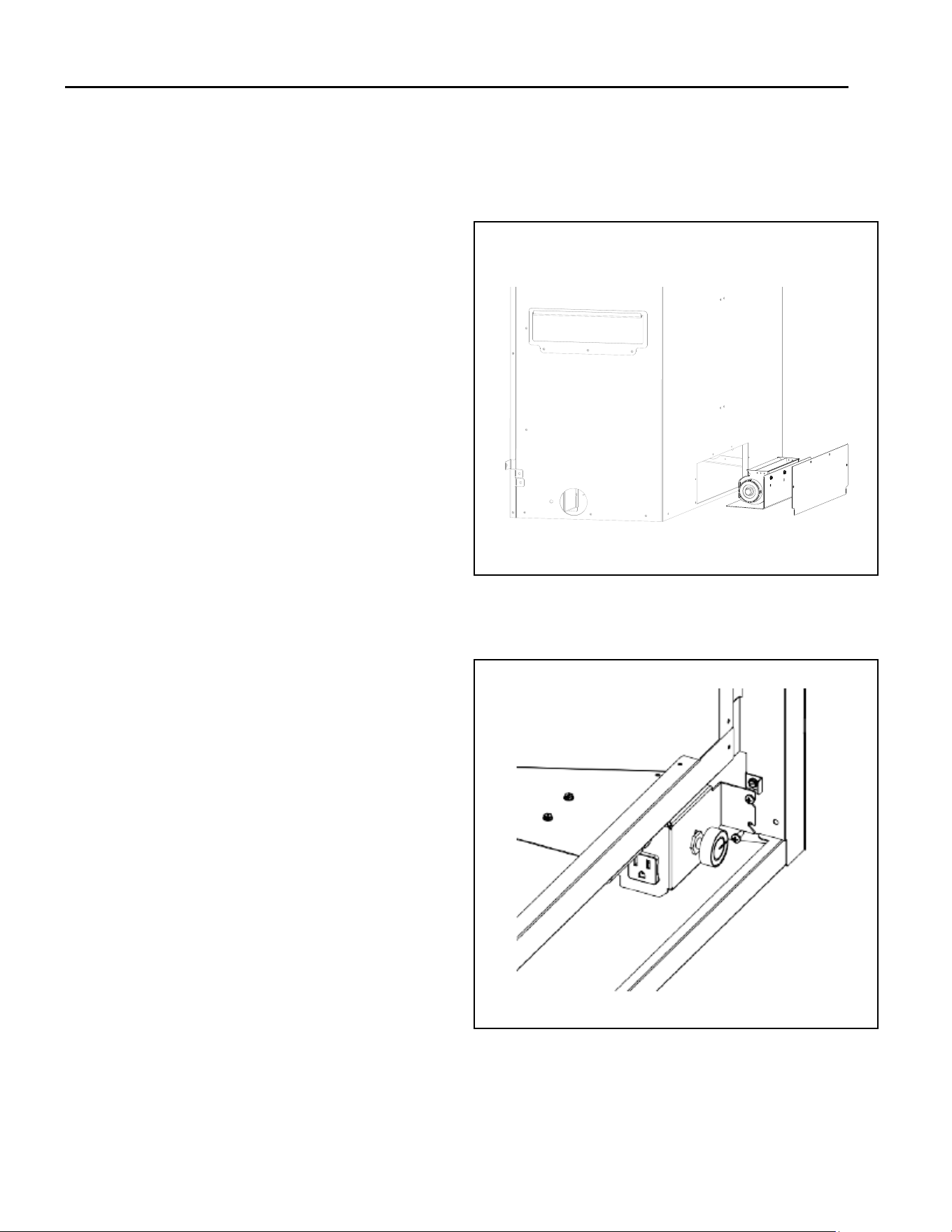
8.6 #SP-028 Oponal Fan Kit (SP-34-MV Only)
WARNING - Electrical Grounding Instrucons: This kit is
equipped with a three-prong (grounding) plug for your
protecon against shock hazard and should be plugged
directly into a properly grounded three-prong receptacle.
Do not cut or remove the grounding prong from this plug.
WANRING: Installaon of this fan kit should be done by a
qualied installer. Verify household breaker is shut o
prior to working on any electrical lines.
NOTE: It is easier to install the fan kit before connecng
the gas line to the control board.
• This appliance, when installed, must be electrically
grounded in accordance with local codes, or in the
absence of local codes, with the Naonal Electrical
Code, ANSI/NFPA 70, or the Canadian Electrical Code,
CSA C22.1.
• Code-approved line voltage wiring, 14 gauge or
beer, must be used when wiring this assembly. Refer
to your local electrical codes for specic require-
ments.
• A pre-installed electrical box is included with the ap-
pliance, along with a receptacle/box cover assembly
in the replace components packet.
• If installing this oponal fan kit aer appliance instal-
laon, remove the control board to access the control
compartment and follow instrucons below. Refer to
8.3 Control Board Removal and Installaon.
This kit includes:
• (1) fan assembly
• (1) temperature control switch with magnet aached
• (2) Phillips head screws (black)
• (1) speed control box with cord
Instrucons:
Before unit installaon, remove the back access panel
(4) screws.
With the motor end facing to the right, slide the fan
underneath the rebox. The fan assembly has mag-
nec tape located on the boom and does not re-
quire mounng.
Mount the speed control box onto the lower right
side frame. Align the slots in the speed control box to
the holes in bracket. Secure with (2) black Philips
head screws (included).
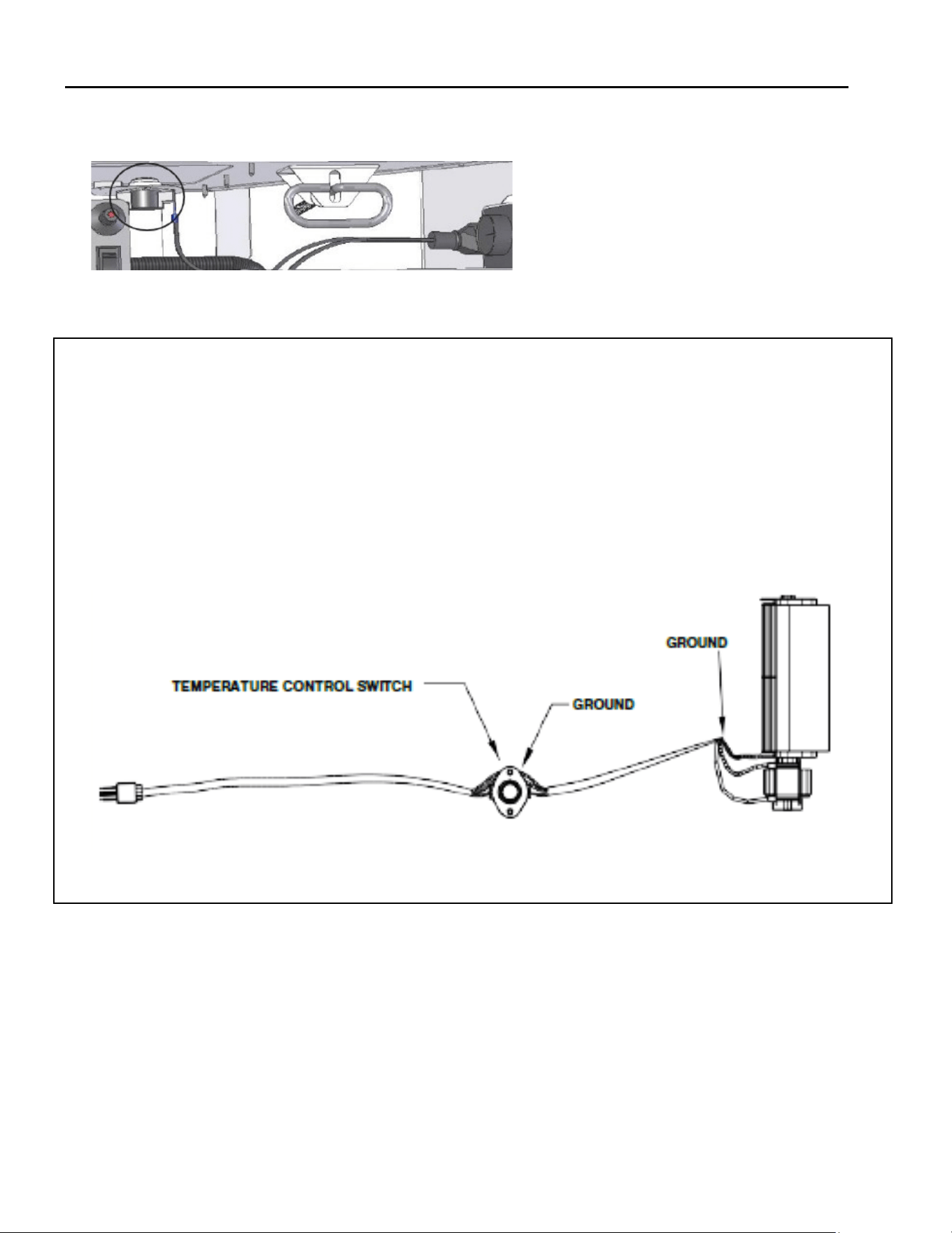
Place the temperature control switch (magnet
aached) onto the rebox oor on the right.
Plug fan cord into the speed control assembly.
Plug the speed control box cord into the electrical box
receptacle.
Reinstall all components previously removed.
Turn speed control counter-clockwise unl it ‘clicks’.
This is the OFF posion. Turn speed control ON by
turning knob clockwise past the ‘click’ -this is the
highest seng.
Figure 8.6 - Fan Kit Installaon Access Cover
Figure 8.7 - Speed Control Locaon
Hussong Mfg. Co, Inc. 49 Rev. 10 - November 2023
SP-34, PFS Report No. 19-553 Starng Serial Number: 23 86710 49
TEMPERATURE CONTROL SWITCH POSITION
Before adjusng temperature control switch, unplug 3-prong
plug on fan cord from receptacle.
Adjust posion of temperature control switch to a warmer loca-
on under rebox to turn fan ON sooner or move it to a cooler
locaon under rebox to turn fan ON later. The fan will turn on
when sensor in temperature control switch reaches 110° F and
will turn OFF when sensor reaches 90° F.
Aer adjustment, plug 3-prong plug on fan cord into receptacle.
Figure 8.8 - Temperature Control Switch

Hussong Mfg. Co, Inc. 50 Rev. 10 - November 2023
SP-34, PFS Report No. 19-553 Starng Serial Number: 23 86710 49
9.0 Electrical Informaon
WARNING: Do not use this replace if any part has been under water. Immediately call a qualied service technician to
inspect this appliance and to replace any part of the control system and any gas control which has been under water.
WARNING - Electrical Grounding Instrucons: This appliance is equipped with a three-prong (grounding) plug for your
protecon against shock hazard and should be plugged directly into a properly grounded three-prong receptacle. Do not
cut or remove the grounding prong from this plug
9.1 Electrical Specicaons
WARNING: An oponal component connecon for the SP34-MV is for low voltage baery or direct current only. Do not con-
nect to 120 or 240 volts. The oponal fan kit is the only component on the MV system that connects to 120 volts.
This appliance, when installed, must be electrically grounded in accordance with local codes, or in the absence of local
codes, with the Naonal Electrical Code, ANSI/NFPA 70, or the Canadian Electrical Code, CSA C22.1.
9.2 Wiring Requirements
9.2.1 SP-34-L Wiring Requirements
• The system requires 120 VAC of electricity and/or baeries to operate.
• Using the baery backup will operate ame modulaon of the burner only.
9.2.2 SP-34-MV Wiring Requirements
• The millivolt gas valve system does not require 120 VAC supply to operate. Do not connect 120 VAC to the gas valve.
• If desired, a thermostat or a wall switch may be installed for main burner operaon control using low voltage wires (not
included).
• The ON/OFF rocker switch will override the thermostat / wall switch. If you choose to leave the rocker switch
wired up it must be placed in the OFF posion to allow the thermostat / wall switch to operate correctly. If you
place the rocker switch in the ON posion it will turn the replace on and override any command from the ther-
mostat / wall switch
• It is oponal to disable the ON/OFF rocker switch by disconnecng the wire from the back of the gas valve. If you
do this then the replace burner will only operate from the commands received from the thermostat / wall
switch.
• If you choose to install the oponal SP-028 fan kit then you will need 120 VAC at the appliance to power the fan kit.
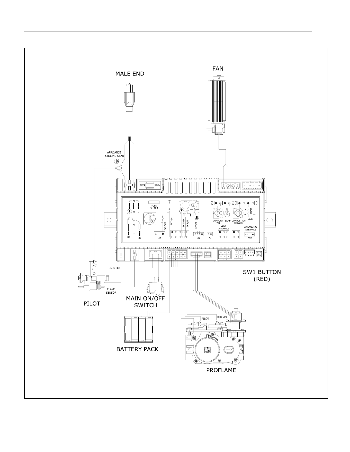
Hussong Mfg. Co, Inc. 51 Rev. 10 - November 2023
SP-34, PFS Report No. 19-553 Starng Serial Number: 23 86710 49
Figure 9.1 - SP-34-L Electrical Diagram
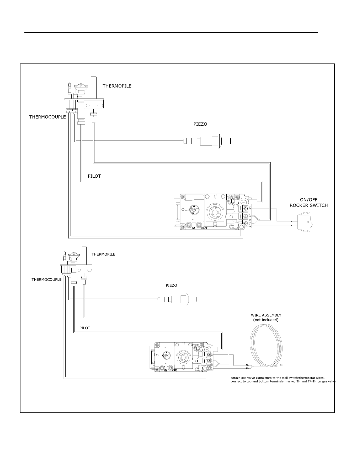
Hussong Mfg. Co, Inc. 52 Rev. 10 - November 2023
SP-34, PFS Report No. 19-553 Starng Serial Number: 23 86710 49
Figure 9.2 - SP-34-MV Electrical Diagram
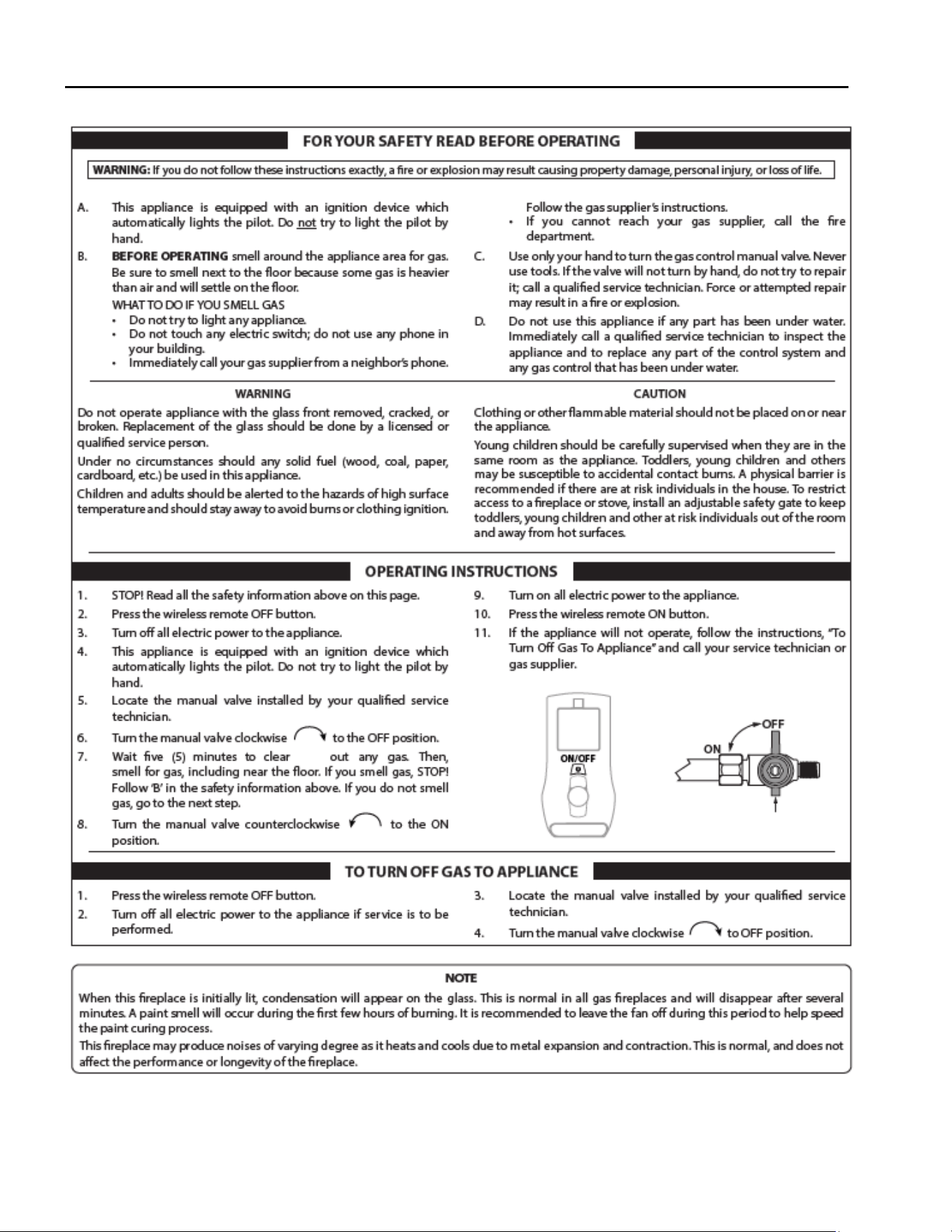
Hussong Mfg. Co, Inc. 53 Rev. 10 - November 2023
SP-34, PFS Report No. 19-553 Starng Serial Number: 23 86710 49
10.0 Operang Instrucons - SP-34-L

Hussong Mfg. Co, Inc. 54 Rev. 10 - November 2023
SP-34, PFS Report No. 19-553 Starng Serial Number: 23 86710 49
10.1 Setup Proame 2 IFC Module
1. Set the main ON/OFF rocker switch in the OFF posi-
on.
2. Install (4) AA baeries (not included) into backup
baery holder on the control module.
3. Install (3) AAA baeries (included in the components
packet) in the remote control baery bay, located at
the base of the remote.
4. Connect the IFC Module to an AC power supply.
10.2 Inialize the Control System
IMPORTANT: Remove all packaging and combusble ma-
terial from the rebox before inializing the control sys-
tem.
NOTE: Performing the next steps will iniate pilot start-
up in manual mode, where the pilot igniter will spark
repeatedly. The pilot will ignite if gas is supplied to the
replace.
1. To access the ON/OFF toggle switch and remote learn
buon on, remove the safety barrier screen by liing
up and out of its slots.
2. Remove the boom frame piece (See Secon 9.2).
Locate the remote sync buon by sliding out the con-
trol module.
3. Press the remote sync buon. The IFC module will
BEEP (3) mes and illuminate an amber LED. This indi-
cates the receiver is ready to synchronize with the
transmier.
4. Within (5) seconds, push the ON/OFF buon on the
remote control. The receiver will BEEP (4) mes to
indicate the transmier’s command is accepted, and
is set to the transmier’s parcular code. The pilot
will automacally ignite.
5. Press the remote control ON/OFF buon again. The
pilot will exnguish, conrming the remote control
command. The control system is now inialized.
6. Set the main ON/OFF rocker switch to ON posion for
remote control operaon of the main burner and re-
place features. Reinstall safety barrier screen.
10.3 Reset the System for Manual Operaon
1. Access the toggle switch and remote learn buon on the
le side of the unit by removing the safety barrier screen
by liing up and out of its slots.
2. Remove the boom frame piece (See Secon 9.2). Locate
the remote sync buon by sliding out the control module.
3. Set the ON/OFF rocker switch to OFF posion.
4. Press and hold the remote sync buon unl it emits (3)
beeps and an amber LED is illuminated.
5. Within (5) seconds, press the remote sync buon again.
This will close synchronizaon with the remote control.
The pilot will automacally light.
• Turn the main burner ON by seng the ON/OFF switch in
ON posion. The main burner will only operate on HI.
• Turn the main burner OFF by seng the ON/OFF switch
in the OFF posion. The pilot will remain lit even if burner
is turned o, provided CPI mode is turned on.
10.4 Automac Safety Turn-o
• This system will execute an automac turn OFF command
for approximately (5) seconds within (24) hours of a con-
nued pilot ame ignion to perform a safety check. This
allows the system to verify correct safety funcons.
• Aer the turn OFF sequence is completed, the IFC module
will re-execute the latest command.
10.5 Backup Baery Operaon
This appliance will operate on the backup baery pack when
electric power is interrupted, or in a power outage. During the
power outage, the appliance burner and ame height adjust-
ment will funcon. The fan and accent light kit will not func-
on.
• The lifespan of the backup baeries depend on various
factors, such as the quality of the baeries, number of
ignions, etc.
• When the backup baery pack is low, the IFC module will
emit a double-beep while receiving an ON/OFF com-
mand. No commands will be accepted aer this alert unl
the back up baeries are replaced. Once replaced, the IFC
module will emit a ‘beep’ as soon as it is powered.

Hussong Mfg. Co, Inc. 55 Rev. 10 - November 2023
SP-34, PFS Report No. 19-553 Starng Serial Number: 23 86710 49
10.6 Control System 7 Day Timeout
• If you have your Proame 2 system set to CPI
(connuous pilot ignion) with 7 consecuve days
without ignion of the main burner, the pilot will turn
o. This a standard safety feature of the SIT Proame
2 system.
• Once you turn CPI on, the 7 day mer will start. If at
any me during the following 7 days your main burn-
er ignites, it will reset the mer back to 7 days.
• See secon 10.9.3 PILOT IGNITION SELECTION for
more informaon.
How to check if your system is set to CPI:
The LCD screen will display the snowake icon.
To select the preferred pilot ignion feature,
1. With the system in the OFF posion, press the mode
key to index the CPI mode icon.
2. Press the up arrow key to acvate CPI.
3. Press the down arrow key to return to IPI. A single
‘beep’ will conrm recepon of the command.
To Turn ON the appliance
1. With the system in the OFF posion, press the remote
control ON/OFF key to turn ON the appliance.
A single ‘beep’ will emit from the IFC module to con-
rm recepon of the command.
The LCD screen will display all acve icons, and the IFC
module will start the ignion sequence.
10.7 IFC Module Ignion Sequence
The IFC module will try (2) mes for ignion, each lasng
approximately (60) seconds, with approximately (35) sec-
onds between each aempt.
1. With the system in OFF posion, press the remote
control ON/OFF key. Approximately (4) seconds aer
this key is depressed, the IFC module will generate
sparks to the pilot hood.
2. First ignion aempt will generate sparks for (60)
seconds.
3. If there is no ame ignion (reccaon) within the
(60) second me frame, the IFC module will stop gen-
erang sparks for approximately (35) seconds.
4. Aer (35) seconds of wait me, the IFC module will
generate sparks for another (60) seconds for the sec-
ond ignion aempt.
5. If there is no posive reccaon aer (60) seconds,
the IFC module will go into a lock out. The red LED will
blink (3) mes, in intervals, unl the system is reset.
10.7.1 Reset IFC Module aer Lockout
10.7.1.1 ON/OFF Rocker Switch
1. Set the ON/OFF rocker switch to the OFF posion.
2. Aer approximately (2) seconds, move the switch to
the ON posion. The ignion sequence will start
again.
10.7.1.2 Remote Control ON/OFF Key
1. Press the remote control ON/OFF key to turn the sys-
tem OFF.
2. Aer approximately (2) seconds, press the ON/OFF
key again. The ignion sequence will start again.
10.7.1.3 Cycling Flame
1. Press the remote control down arrow key during
ame adjustment mode to reduce the ame to OFF
(indicated by OFF displayed on the LCD screen).
2. Aer approximately (2) seconds, press the up arrow
key. The ignion sequence will start again.
10.8 Addional Diagnosc Informaon
Low Baery Condion (<4V) Remote Control:
• Baery Icon will appear on LCD remote control dis-
play.
• Replace baeries.
Low Baery Condion (<4V) Baery Backup:
• The red LED Indicator will blink (1) me in intervals.
• A low double-beep emits from the IFC control module
when it receives an ON/OFF command from the re-
mote control.
• Replace Baeries.
Pilot Flame Error Condion:
• Red LED Indicator will blink (2) mes in intervals. Con-
tact your dealer if this occurs.
System Lock Out Condion:
• Red LED Indicator will blink (3) mes in intervals.
• Verify gas is turned on.
• Verify sensor is not shorted.
• Follow secon 10.2, INITIALIZE THE CONTROL SYS-
TEM.
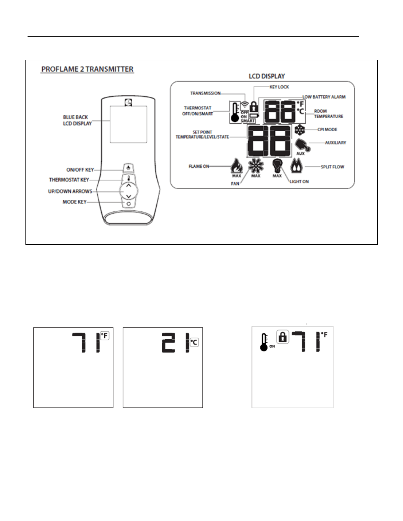
Hussong Mfg. Co, Inc. 56 Rev. 10 - November 2023
SP-34, PFS Report No. 19-553 Starng Serial Number: 23 86710 49
10.9 Remote Control Operaon
10.9.1 Temperature Display
1. With the system in the OFF posion, simultaneously press
the thermostat key and the mode key to change degrees
from °F to °C
2. Visually check the LCD screen to verify either °F or °C is
displayed on the right side of the room temperature dis-
play.
10.9.2 Key Lock
This funcon locks the keys to avoid unsupervised opera-
on. Once acvated, a lock icon will appear on the LCD
screen.
1. Simultaneously press the mode key and the up arrow
key to acvate or deacvate this funcon.
Figure 10.2 - Temperature Display
Figure 10.1 - Remote control overview
Figure 10.3 - Key Lock
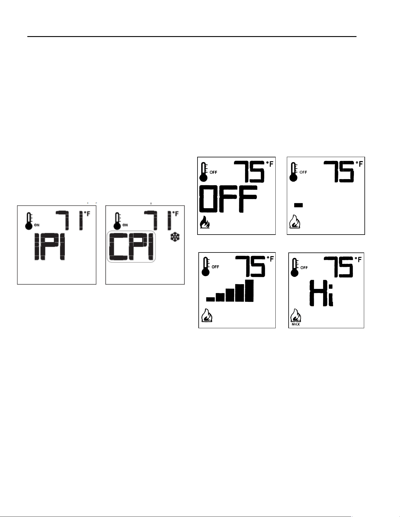
Hussong Mfg. Co, Inc. 57 Rev. 10 - November 2023
SP-34, PFS Report No. 19-553 Starng Serial Number: 23 86710 49
10.9.3 Pilot Ignion Selecon (IPI/CPI)
This system has the opon of a connuous (standing)
pilot. This features allows the system to change from a
spark-to-pilot system to the standing pilot opon. The
standing pilot will keep the rebox warm and establish a
dra in the vent, which allows the main burner to ignite
with less air-ow disrupon.
When the system is OFF, the LCD screen will display the
snowake icon during the setup of either IPI or CPI mode.
To select the preferred pilot ignion feature,
With the system in the OFF posion, press the mode
key to index the CPI mode icon.
Press the up arrow key to acvate CPI.
Press the down arrow key to return to IPI. A single
‘beep’ will conrm recepon of the command.
When the system is ON,
IPI mode: LCD screen will not display the snowake icon
CPI mode: LCD screen will display the snowake icon
10.9.6 Remote Control Flame Adjustment
This control system has (6) ame levels. If the smart thermo-
stat operaon is acvated, then the manual adjustment of the
ame height will be disabled.
Verify the system is in the ON posion and the ame level
is set at maximum.
Press the down arrow key once to reduce ame height by
one level unl the ame is turned o.
Press the up arrow key once to increase ame height by
one step. If the up arrow key is pressed while the system
is on, but the ame is o, the ame will ignite on HI.
A single ‘beep’ will conrm recepon of the command.
Figure 10.4 - Pilot Selecon
10.9.4 Turn ON the Appliance
With the system in the OFF posion, press the remote
control ON/OFF key to turn ON the appliance. A single
‘beep’ will emit from the IFC module to conrm recep-
on of the command.
The LCD screen will display all acve icons, and the IFC mod-
ule will start the ignion sequence.
10.9.5 Turn OFF the appliance
1. With the system in the OFF posion, press the remote
control ON/OFF key to turn ON the appliance. A single
‘beep’ will emit from the IFC module to conrm recep-
on of the command.
The LCD screen will only display the room temperature and
its icon, and the IFC module will turn o the main burner.
Flame O Flame Level 1
Flame Level 5 Flame Level Maximum
Figure 10.5 - Flame Adjustment
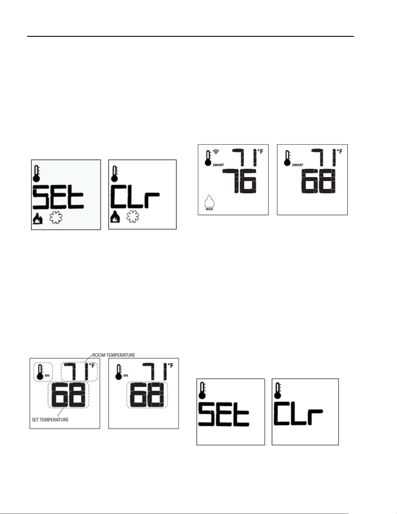
Hussong Mfg. Co, Inc. 58 Rev. 10 - November 2023
SP-34, PFS Report No. 19-553 Starng Serial Number: 23 86710 49
10.9.6.1 Deacvate Flame Modulaon
1. Verify all (3) AAA baeries are installed in the remote
control baery bay.
2. Remove (1) AAA baery.
3. Press and hold the on/o key and the mode key at
the same me.
4. Reinsert (1) AAA baery.
5. While sll holding the on/o key, let go of ONLY the
mode key.
6. Index over to the ame graphic on the LCD screen to
edit. Use the up or down arrow key to choose ‘SEL’ or
‘CLR’. “SEL” means ame modulaon is turned on and
“CLR” means ame modulaon is turned o.
10.9.7.2 Smart Thermostat
The smart thermostat funcon will adjust the ame height
based on the set temperature and the actual room tempera-
ture. The smart thermostat funcon automacally adjusts the
ame down when the room temperature reaches the set
point. To acvate this funcon,
Press the thermostat key unl the ‘SMART’ appears on
LCD screen on the right side of the temperature bulb
graphic.
To adjust the set temperature, press the up or down ar-
row keys unl the desired temperature is displayed on
the LCD screen.
Figure 10.6 - Deacvate Flame Modulaon
10.9.7 Remote Control Thermostat Operaon
10.9.7.1 Room Thermostat
The remote control can operate as a room thermostat.
The thermostat can be set to a desired temperature to
control a room’s comfort level. To acvate this funcon,
1. Press the thermostat key. The LCD screen will display
a temperature bulb graphic, the room temperature
and set temperature.
2. To adjust the set temperature, press the up or down
arrow keys unl the desired temperature is displayed
on the LCD screen.
Figure 10.7 - Thermostat Operaon
Figure 10.8 - Smart Thermostat Operaon
10.9.7.3 Deacvate Remote Control Thermostat
Operaon
The thermostat operaon funcon can be deacvated. The
remote control will sll operate the main burner on and o,
and funcon ame, fan, and light modulaon. To deacvate
this funcon,
Verify all (3) AAA baeries are installed in the remote
control.
Remove (1) AAA baery.
While reinserng the baery, push and hold the thermo-
stat key. You will see “CLR” across the screen. This means
the thermostat funcon is turned o. The temperature
bulb graphic will not be displayed on the LCD screen.
• To reacvate remote thermostat operaon, follow the
same key sequence procedure above. The screen will
then say “SEL” which means the thermostat funcon is
turned on. The temperature bulb graphic will reappear on
the LCD screen.
Figure 10.9 - Deacvate Thermostat Operaon
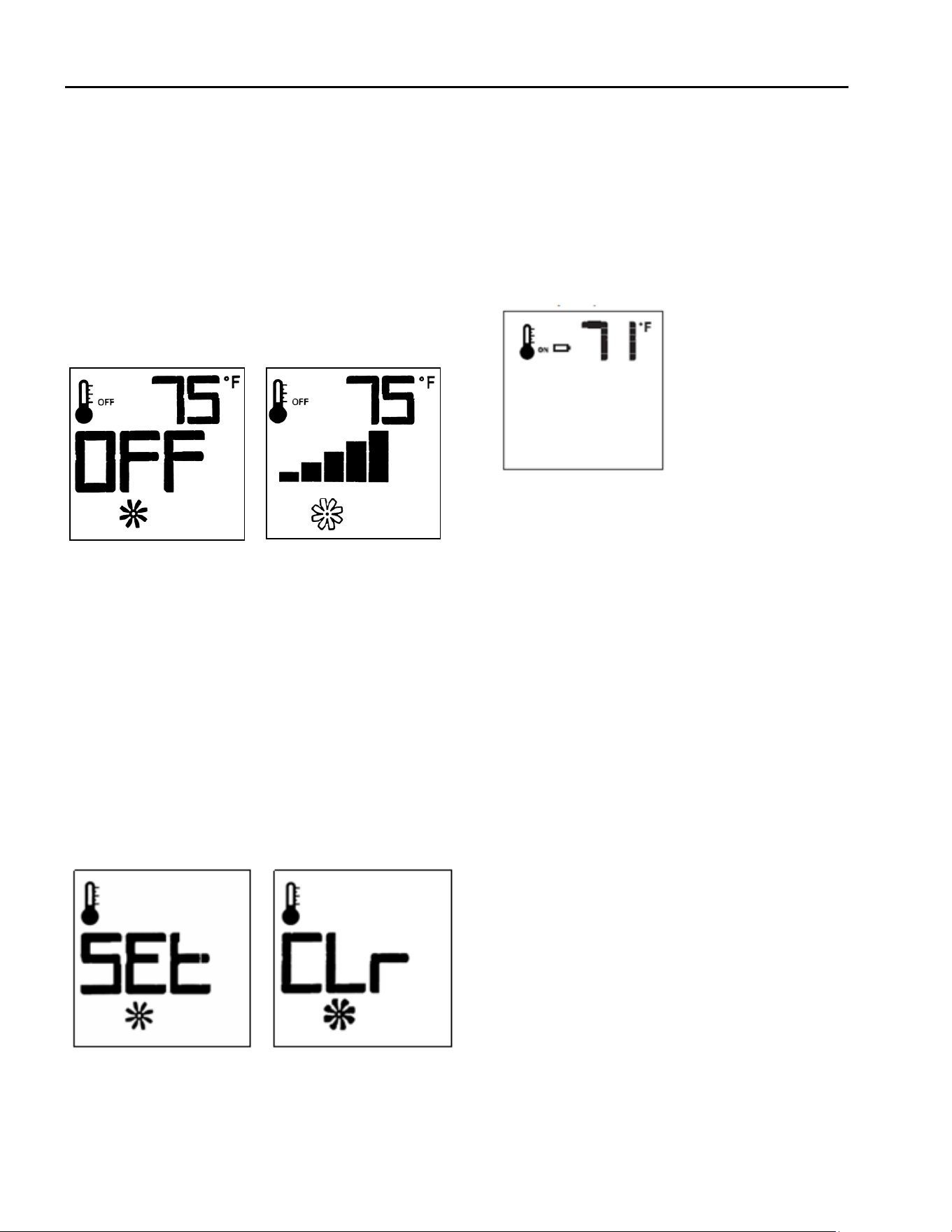
Hussong Mfg. Co, Inc. 59 Rev. 10 - November 2023
SP-34, PFS Report No. 19-553 Starng Serial Number: 23 86710 49
10.9.8 Fan Speed Control
Fan speed can be adjusted through (6) speeds. To acvate
this funcon,
Press the mode key to index to the fan control icon.
Press the up or down arrow keys to turn on, o, or to
adjust fan speed.
Thermostat mode: Fan(s) have a (5) minute delay me
when the replace is lit. This allows me for heat to build
in replace before fan operaon. The fan will connue to
operate for approximately (12) minutes aer the replace
has been turned o.
Manual mode: Fan(s) will operate at previous seng.
There is no delay in start up or stop me.
Figure 10.10 - Fan adjustment
10.9.8.1 Deacvaon Fan Speed Control
Fan speed can be adjusted through (6) speeds. To acvate this
funcon,
1. Verify all (3) AAA baeries are installed in the remote
control baery bay.
2. Remove (1) AAA baery.
3. Press and hold the on/o key and the mode key at the
same me.
4. Reinsert (1) AAA baery.
5. While sll holding the on/o key, let go of ONLY the
mode key.
6. Index over to the fan control icon on the LCD screen to
edit. Use the up or down arrow key to choose ‘SEL’ or
‘CLR’.
Figure 10.11 - Fan Control Deacvaon
10.9.9 Remote Control Low Baery Detecon
Remote control baery lifespan depends on various fac-
tors including baery quality, number of ignions, chang-
es to room thermostat set point, etc.
• When the remote control baeries are low, a baery
icon will appear on the LCD display before all baery
power is lost.
• When the baeries are replaced, this icon will disap-
pear.
Figure 10.12 - Low Baery
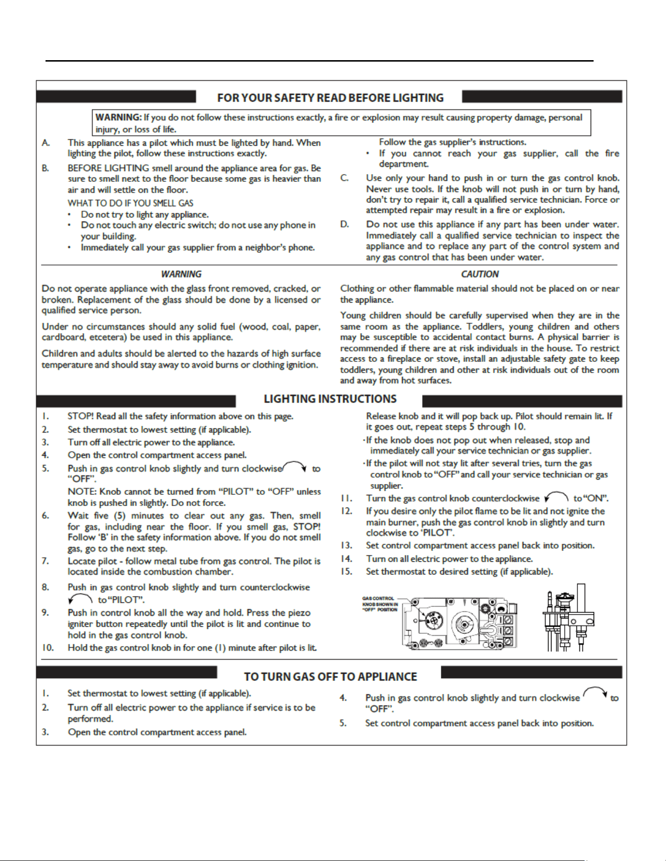
Hussong Mfg. Co, Inc. 60 Rev. 10 - November 2023
SP-34, PFS Report No. 19-553 Starng Serial Number: 23 86710 49
11.0 Operang Instrucons - SP-34-MV
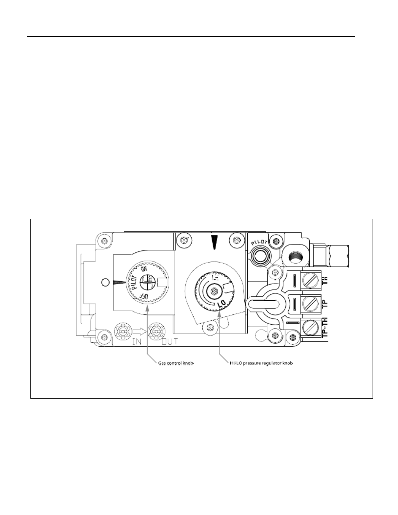
Hussong Mfg. Co, Inc. 61 Rev. 10 - November 2023
SP-34, PFS Report No. 19-553 Starng Serial Number: 23 86710 49
11.1 Flame Height and Heat Output Adjustment
Model #SP-34-MV (millivolt system) is equipped with a manual HI/LO pressure modulator knob, located on the gas valve, for
adjusng main burner ame height and the heat output of the replace.
• Open the control compartment access panel to access the gas valve and the HI/LO pressure regulator knob.
• To adjust, turn the HI/LO knob counterclockwise to LO posion or clockwise to HI posion, unl desired ame appearance
and heat output is achieved.
11.2 7 Day Time-out Pilot-on- Demand Installaons
For regions that require installaons a 7 day me-out (refer to your local dealer to see if this applicable to your installaon),
model #SP-34-MV is ed with a millivolt Pilot-on-Demand gas control valve equipped with a mer set for 7 consecuve days
once the pilot has been ignited. If there is no appliance operaon within the 7 days, the main burner and/or the pilot will turn
o, but the gas control knob will sll be set in its original posion (‘PILOT’ or ‘ON’).
• You must manually cycle the system to reignite operaon.
• This a standard safety feature of the SIT Millivolt Pilot-on-De- mand control system.
• Once you turn the pilot on, the 7 day mer will start. If at any me during the following 7 days your main burner ignites, it
will reset the mer back to 7 days.
To operate your millivolt pilot-on-demand system, open the control compartment access panel to access the gas valve and gas
control knob. Refer to the lighng instrucons on the previous page for lighng procedures and safety informaon.
Figure 11.1 MV Gas Control Valve
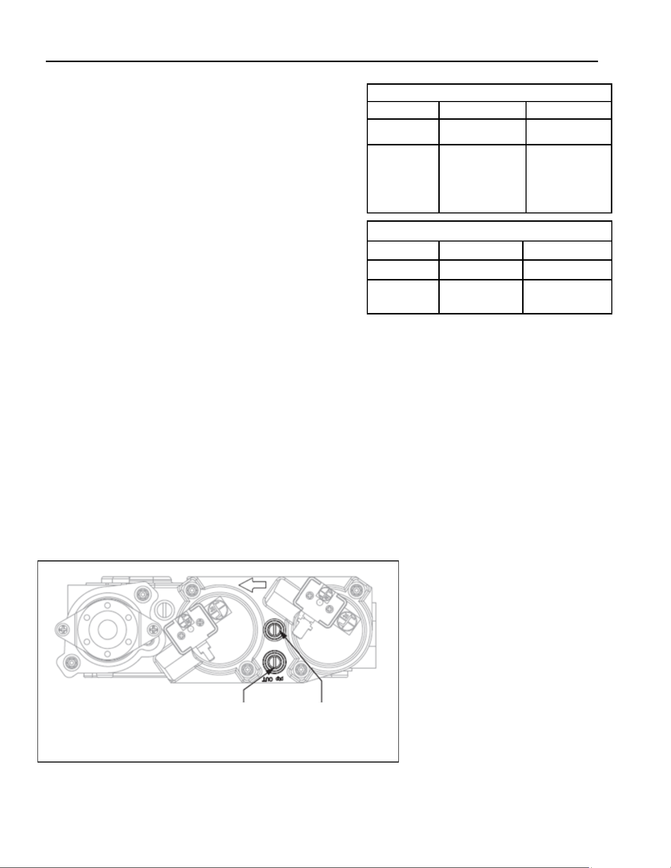
Hussong Mfg. Co, Inc. 62 Rev. 10 - November 2023
SP-34, PFS Report No. 19-553 Starng Serial Number: 23 86710 49
12.0 Pressure Tesng and Burner Adjustments
12.1 Pressure Tesng (SP-34-L)
NOTE: The appliance and its appliance main gas valve
must be disconnected from the gas supply piping system
during any pressure tesng of the system at test pres-
sures in excess of 1/2 psi (3.5 kPa).
IMPORTANT: Pressure check taps for manifold (outgoing)
and inlet (incoming) pressure have been incorporated
into the valve. The pressure tap marked OUT measures
outgoing pressure. The pressure tap marked IN measures
incoming pressure.
12.1.1 Inlet Pressure Test
NOTE: Make sure to apply these incoming pressure test
with all other gas appliances on, or at full capacity, in the
house for proper pressure reading.
IMPORTANT: If the inlet pressure reading is too high or
too low, contact the gas company. Only a qualied gas
service technician should adjust incoming gas pressure.
1. Loosen the inlet (IN) pressure tap by turning screw
counter-clockwise. See (A) in FIGURE 12.1.
2. Aach manometer using a 1/4” (6mm) I.D. hose.
3. Light pilot and burner. Check pressure to ensure it is
between the minimum and maximum recommended
pressure sengs (TABLE 12.1).
4. Turn o burner and pilot.
5. Disconnect hose and ghten the inlet (IN) pressure
tap by turning screw clockwise. Screw should be snug.
Do not over ghten.
6. Relight pilot and burner. Then reaach manometer to
the inlet pressure tap (A) to verify the tap is com-
pletely sealed. Manometer should read no pressure.
Table 12.1 Inlet Pressures
Fuel Natural Gas Propane
Gas Supply Min-Max Min-Max
Inlet Pressure
Tap (A)
5” - 10.0” WC
(1.25 - 2.49 kPa)
7” WC (1.74 kPa)
recommended
11”-13” WC
(2.74 - 3.24 kPa)
Table 12.2 Manifold Pressures
Fuel Natural Gas Propane
Gas Supply Low - High Low - High
Inlet Pressure
Tap (A)
1.6” - 3.5” WC
(0.41 - 0.87 kPa)
6.4” - 10” WC
(1.59 - 2.48 kPa)
Figure 12.1 - Pressure Check Taps
12.1.2 Manifold Pressure Test
1. Light pilot.
2. Loosen manifold (OUT) pressure tap by turning screw
counter-clockwise. See (B) in FIGURE 12.1.
3. Aach manometer to pressure tap using a
1/4” (6mm) I.D. hose.
4. Light burner. Check manometer reading. Refer to
TABLE 12.2.
5. Turn burner and pilot o.
6. Disconnect manometer hose and ghten the manifold
(OUT) pressure tap by turning screw clockwise. Screw
should be snug. Do not over ghten.
7. Aach the manometer to the manifold pressure tap
(B) to verify it is completely sealed. The manometer
should read no pressure when pilot and burner are
on.
B) Manifold Pressure Tap A) Inlet Pressure Tap
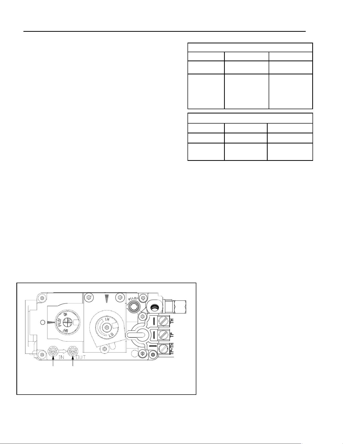
Hussong Mfg. Co, Inc. 63 Rev. 10 - November 2023
SP-34, PFS Report No. 19-553 Starng Serial Number: 23 86710 49
12.2 Pressure Tesng (SP-34-MV)
IMPORTANT: Pressure check taps for manifold (outgoing)
and inlet (incoming) pressure have been incorporated into
the valve. The pressure tap marked OUT measures out-
going pressure. The pressure tap marked IN measures
incoming pressure.
12.2.1 Inlet Pressure Test
NOTE: Make sure to apply the incoming pressure test with
all other gas appliances on, or at full capacity in the house
for a proper pressure reading. If the inlet pressure reading
is too high or too low, contact the gas company. Only a
qualied gas service technician should adjust incoming gas
pressure. A low pressure can cause a delayed ignion.
1. Loosen the inlet (IN) pressure tap by turning screw
counterclockwise. See (A) in Figure 12.2.
2. Aach manometer using 1/4” (6mm) I.D. hose.
3. Light pilot.
4. Turn the gas control knob to ON. Burner should not
light. Note the manometer reading.
5. Press the ON/OFF rocker switch to ON. Check pres-
sure to ensure it is near maximum inlet pressure.
6. Press the ON/OFF rocker switch to OFF.
7. Turn the gas control knob to OFF.
8. Disconnect hose and ghten the inlet (IN) pressure
tap by turning screw clockwise. Screw should be snug.
Do not over ghten.
9. Relight pilot and turn the gas control knob to ON. Re-
aach manometer to the inlet pressure tap (A) to
verify the tap is completely sealed. Manometer
should read no pressure.
Table 12.3 Inlet Pressures
Fuel Natural Gas Propane
Gas Supply Min-Max Min-Max
Inlet Pressure
Tap (A)
5” - 10.0” WC
(1.25 - 2.49 kPa)
7” WC (1.74 kPa)
recommended
11”-13” WC
(2.74 - 3.24 kPa)
Table 12.4 Manifold Pressures
Fuel Natural Gas Propane
Gas Supply Low - High Low - High
Inlet Pressure
Tap (A)
1.6” - 3.5” WC
(0.41 - 0.87 kPa)
6.4” - 10” WC
(1.59 - 2.48 kPa)
Figure 12.2 - Pressure Check Taps
12.2.2 Manifold Pressure Test
1. Light pilot.
2. Loosen manifold (OUT) pressure tap by turning screw
counter-clockwise. See (B) in FIGURE 12.3.
3. Aach manometer to pressure tap using a 1/4” (6mm)
I.D. hose.
4. Turn gas control knob to ON.
5. Press the rocker switch to ON and note manometer read-
ing.
6. Disconnect manometer hose and ghten the manifold
(OUT) pressure tap by turning screw clockwise. Screw
should be snug. Do not over ghten.
7. Aach the manometer to the manifold pressure tap (B)
to verify it is completely sealed. The manometer should
read no pressure when pilot and burner are on.
A) Inlet Pressure Tap B) Manifold Pressure Tap
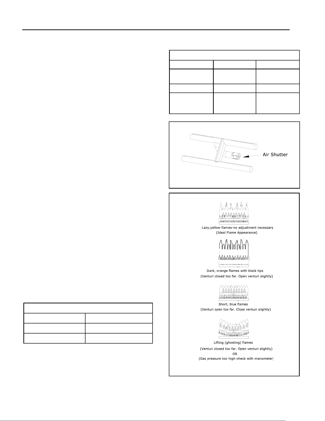
Hussong Mfg. Co, Inc. 64 Rev. 10 - November 2023
SP-34, PFS Report No. 19-553 Starng Serial Number: 23 86710 49
12.3 Flame Appearance Adjustment
WARNING: To avoid property damage or personal injury,
allow the replace ample me to cool before making any
adjustments.
Burner ame appearance and characteriscs are aected by
altude, fuel quality, venng conguraon, and other fac-
tors. Aer installaon, this appliance may need addional
adjustments to achieve opmum ame appearance and
visual aesthecs.
12.3.1 Burner Venturis
WARNING: VENTURI ADJUSTMENT MUST BE DONE BY A
QUALIFIED SERVICE TECHNICIAN.
NOTE: Burner venturi air shuer sengs have been factory
set. Refer to TABLE 12.5.
When this appliance is rst lit, the burner ames will appear
blue. During the rst 15 minutes of operaon, ame appear-
ance will gradually turn to the desired yellow appearance. If
the ames remain blue or become dark orange with evi-
dence of soong (black ps), adjustment of the air shuer
opening may be necessary.
Regardless of venturi orientaon, closing the air shuer will
achieve a desired yellow ame, but may produce soot on
the glass. Opening the air shuer will cause a short, blue
ame that may li o the burner.
12.3.2 Venturi Opening Adjustments
NOTE: If soot is present on the glass, check log posioning
before adjusng the venturi. Logs must not block burner
ports.
1. Open components access cover.
2. Remove the safety barrier and glass frame assembly.
3. Remove log set, lava rock, and panels (if installed).
4. Loosen screw on venturi and adjust as necessary. Re-
ghten screw.
5. Reinstall all components previously removed.
6. Set component access cover back into closed posion.
IMPORTANT: Slight adjustments to the venturi opening will
create dramac results. Adjust at slight increments unl
desired look is achieved. Always burn the replace for at
least 15 minutes and allow the appliance ample me to cool
before making further adjustments.
Table 12.5 Factory Set Venturi Openings
Fuel Air Shuer Sengs
Natural Gas
1/16” (1.5mm) OPEN
Propane
5/8” (16mm) OPEN
Table 12.6 Flame Appearance Venturi Adjustment
Flame Characteriscs Cause Soluon
Dark, orange ame
with black ps
Venturi closed too far Open venturi slightly
Short, blue ames Venturi open too far Close seng slightly
Liing (ghosng)
ames
Gas pressure too high
and/or venturi closed
too far
Check manometer
sengs and/or open
venturi seng slightly
Figure 12.4 - Flame Appearance and Characteriscs
Figure 12.3 - Burner Venturis
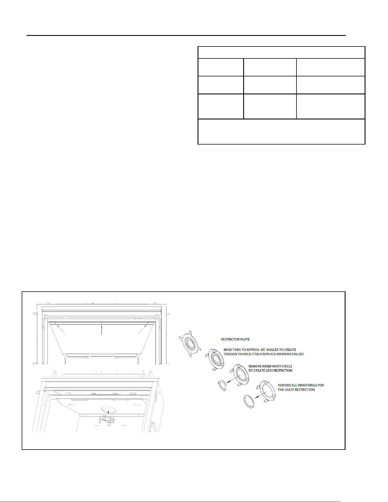
Hussong Mfg. Co, Inc. 65 Rev. 10 - November 2023
SP-34, PFS Report No. 19-553 Starng Serial Number: 23 86710 49
12.3.3 Vent Restricon (aer installaon)
WARNING: To avoid property damage or personal injury,
allow the replace ample me to cool before making any
adjustments.
WARNING: Improper vent installaon may cause the burner
ames to li or “ghost.” Perform a visual check on ame
appearance aer restricon adjustment to ensure proper
performance.
Vercal terminaons may display an acve, compact ame.
If this appearance is not desirable, a restrictor plate may
need to be installed or modied aer vent terminaon in-
stallaon. Access to the vent exit for restricon can be
reached through the replace bae. See Figure 12.5
Refer to TABLE 12.7 and FIGURE 12.4 for ame appearance
adjustments. Allow the replace to burn for 15 minutes
before making any adjustments.
Restrictor Plate Installaon
1. Open the component access cover. Remove the safety
barrier and glass frame assembly.
2. Remove refractory (if installed) and log set.
3. Remove (3) screws at the rebox ceiling securing the
bae. Li the bae out of slots on the rebox back
wall.
4. Bend the tabs on the restrictor (included in replace
components packet) to approximately 80° angles. This
will create tension when the restrictor is inserted into
the exhaust pipe.
5. Insert restrictor into the 4” (102mm) exhaust pipe with
the tabs poinng towards you.
6. Reinstall the replace bae with screws previously
removed and other components.
7. Close the component access cover.
Table 12.7 Restrictor Plate Adjustment Guidelines
Flame Appearance Dra Problem Soluon
Short, ickering Excessive dra and/or
not enough restricon
Add restrictor plate
Liing or ghosng Insucient dra Remove inner ring(s) on re-
strictor plate or remove re-
strictor plate
*If ames connue to li or ghost aer opening the restrictor plate and verify-
ing correct vent installaon, shut o the gas supply and call a qualied service
technician.
Restrictor Plate Modicaon
1. Open the component access cover. Remove the safe-
ty barrier and glass frame assembly.
2. Remove refractory (if installed) and log set.
3. Remove (3) screws securing the replace bae.
4. Remove the restrictor from the 4” (102mm) exhaust
pipe by pulling the restrictor down and out.
5. Make necessary modicaons to achieve desired
ame appearance.
6. Insert restrictor into the 4” (102mm) exhaust pipe
with the tabs poinng towards you.
7. Reinstall the replace bae with (3) screws previous-
ly removed.
8. Reinstall all components previously removed.
Figure 12.5 - Restrictor Installaon
Hussong Mfg. Co, Inc. 66 Rev. 10 - November 2023
SP-34, PFS Report No. 19-553 Starng Serial Number: 23 86710 49
13.0 Troubleshoong
13.1 Electronic Ignion System (SP-34-L)
ATTENTION: Troubleshoong must be performed by a qualied technician.
Before proceeding with the steps in the following troubleshoong guide,
• Verify inlet pressure meets the recommended inlet pres-
sure. If necessary, adjust line pressure regulator.
• Verify the communicaon link is established between the
remote control and the IFC module.
• CAUTION: Label all wires prior to disconnecon when ser-
vicing controls. Wiring errors can cause improper and dan-
gerous operaon. Verify proper operaon aer servicing.
Issue Cause Soluon
Pilot will not light Electrical power interrupted or
disconnected
Restore electrical power to appliance or use baery
back-up
Wiring disconnecon Ensure baeries are fully charged if using baery back-
up as power source.
Use wiring schemac in this manual to determine that
all wiring connecons are secure and correct.
Gas supply turned o Check remote shut-o valves from the appliance. Usu-
ally there is a valve near the main gas line. There may
be more than (1) valve between the appliance and
main gas line.
Pilot will not stay lit No propane in tank Check propane tank. Rell if necessary.
Low gas pressure Consult a plumber or gas supplier
Can be caused by situaon such as a bent line, too nar-
row diameter or pipe, or a low line pressure
Pilot adjustment screw not sealed Seal pilot adjustment screw. Do not over-ghten.
Pilot ame not making contact
with the ame reccaon sen-
sor on the pilot assembly
Verify the pilot envelopes the top of the ame sensor
and extends far enough onto the burner for ignion
Pilot ame always on, or will
not exnguish
Control system set to CPI mode. Set control system to IPI mode.
• Verify proper 120VAC power supply to the control
module.
• Verify the control module back-up baery pack and
the remote control baeries are fresh and installed
with correct polarity.
• Verify all connecons between the wire harnesses
and the system components are proper and posive.
Hussong Mfg. Co, Inc. 67 Rev. 10 - November 2023
SP-34, PFS Report No. 19-553 Starng Serial Number: 23 86710 49
Issue Cause Soluon
Burner ame will not light ON/OFF rocker switch in OFF posion Switch rocker switch to ON posion.
Gas supply turned o Check for mulple shut-os in the supply line.
Verify gas supply is turned on.
Low gas supply Consult with plumber or gas supplier.
Check propane tank. Rell if necessary.
Wiring disconnecon or improper
wiring
Check for faulty or incorrect wiring. Refer to FIG-
URE 9.0, Electrical Informaon.
Plugged burner orice Remove blockage.
Pilot ame Verify the pilot ame is properly directed to ignite
burner. See pilot ame troubleshoong in this
secon.
Remote control not working Replace Baeries.
No call for heat Verify remote control is powered ON and thermo-
stat operaon is turned OFF.
No propane in tank Check propane tank, Rell if necessary. Pilot and burner exnguish
while in operaon
Incorrect glass assembly installaon Refer to secon 8.1, GLASS FRAME ASSEMBLY.
Incorrect vent cap installaon Adjust if necessary.
Vent cap blockage Remove debris if necessary.
Improper pitch on horizontal venng 1/4” (6mm) rise for ever 12” (305mm) of travel is
required on horizontal venng.
Exhaust vent pipe leaking exhaust
gases back into rebox
Check for leaks and repair if necessary.
Excessive dra A restrictor may need to be installed or modied.
Refer to secon 12.3.3 Vent Restricon.
Soot appears on glass Improper log placement Refer to secon 8.4, SP34A LOG SET INSTALLA-
TION.
Improper venturi sengs Venturi air shuers may need to be opened slight-
ly to allow more air into the gas mix. Refer to sec-
on 12.3.1, BURNER VENTURIS.
Incorrect vent cap installaon Adjust if necessary.
Vent cap blockage Remove debris if necessary.
Hussong Mfg. Co, Inc. 68 Rev. 10 - November 2023
SP-34, PFS Report No. 19-553 Starng Serial Number: 23 86710 49
Issue Cause Soluon
Flame burns blue and lis o
burner
Improper venturi seng The venturi air shuer may need to be
close slightly to allow less air into the gas
mix. Refer to secon 12.3.1, BURNER VEN-
TURIS.
Incorrect vent cap installaon Adjust if necessary.
Blockage or leakage of the vent system Check the vent pipes for leaks and the vent
cap for debris. Repair the vent pipes or
remove debris from vent cap, if necessary.
Baery backup baeries or remote control
baeries low
Replace the baeries. No reacon to command
No communicaon between remote con-
trol and control module
Reprogram remote control to IFC module
A maximum number of failed ignions or
ame restoraons has been reached.
Reset IFC module
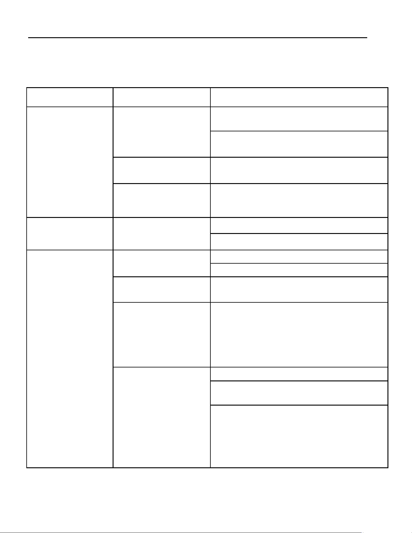
Hussong Mfg. Co, Inc. 69 Rev. 10 - November 2023
SP-34, PFS Report No. 19-553 Starng Serial Number: 23 86710 49
13.2 Millivolt Ignion System (SP-34-MV)
ATTENTION: Troubleshoong must be performed by a qualied technician.
Issue Cause Soluon
No spark from electrode to
pilot when piezo buon is
triggered
Piezo igniter wiring disconnecon Verify piezo igniter is properly grounded. Tighten mounng
fastener, if required.
Check and repair, if necessary, the wire connecons between
the piezo igniter and igniter electrode.
Wiring disconnecon Check the wiring at back of electrode igniter for proper con-
necon
Incorrect electrode posion Verify there is a 1/8” (3mm) gap between the electrode and
pilot. Readjust if necessary. Direct metal contact may cause an
arc below the electrode and along the electrode wire.
Spark igniter will not light
aer repeated triggering of
the piezo buon
No gas Check for mulple shut-o valves in the supply line.
Check propane tank for gas supply. Rell if necessary.
Pilot will not stay lit aer
carefully following lighng
instrucons
Pilot ame does not impinge on
thermocouple
Clean pilot hood.
Adjust pilot ame at gas valve for proper ame impingement.
Loose thermocouple connecon Ensure thermocouple from valve is fully inserted and ght—
hand ght plus 1/4 turn.
Thermocouple reading below 15
millivolts
Disconnect the thermocouple form the valve. Place one milli-
volt meter lead wire on the end of the thermocouple, and the
other millivolt meter lead wire on the thermocouple’s copper
wire. Start the pilot while holding the gas valve control knob in.
If the millivolt reading is less than 15 millivolts, replace ther-
mocouple.
Thermopile not generang
sucient millivolts
Adjust, if necessary, the pilot ame to envelope thermopile.
Check thermopile connecons are properly wired to the gas
control valve. Tighten if necessary.
Measure millivolt producon with a millivolt meter. Turn re-
mote / thermostat / wall switch, or ON/OFF rocker switch to
OFF. Turn the gas valve control to the PILOT posion (pilot
should remain lit). Take millivolt reading at TH-TP and TP ter-
minals on gas valve. Reading should be 350 millivolts, mini-
mum. If reading is less than 350 millivolts, replace thermopile.
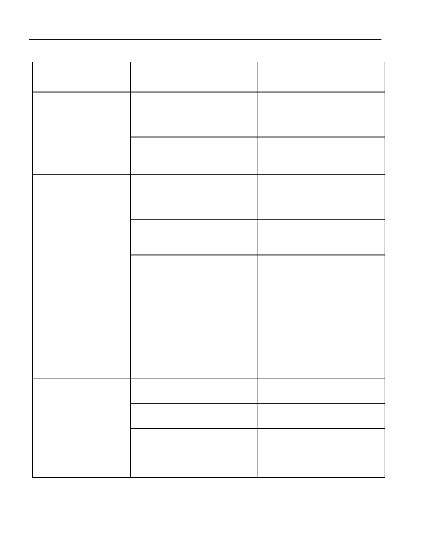
Hussong Mfg. Co, Inc. 70 Rev. 10 - November 2023
SP-34, PFS Report No. 19-553 Starng Serial Number: 23 86710 49
Issue Cause Soluon
Frequent pilot outages Pilot shield not installed Install pilot shield.
Pilot safety dropout Pilot ame is too high or too low. Clean
pilot hood and adjust pilot ame for maxi-
mum ame impingement on thermopile.
Burner will not light Light instrucons not followed Turn gas control knob to ON posion. Turn
the ON/OFF rocker switch to ON posion.
Put wall switch, remote, or thermostat in
heat demand posion .
Plugged main burner orice Remove blockage as necessary.
Switching device is defecve Check remote, thermostat, or wall switch
wires for proper connecon.
Place jumper wires across terminals at
switch. If burner lights, replace the defec-
ve switch, thermostat, or baeries in
remote control as necessary.
If switching device checks out as described
above, place jumper wires across switches
on the gas valve. If the burner lights, the
switching wires are faulty, or connecons
are bad. Replace as necessary.
Thermopile wires loose at valve terminals Tighten if necessary. Burner will not stay lit
Thermopile wires ground out due to
pinched wires
Free pinched wires if necessary.
Improper refractory panel placement (if
installed)
Refractory panels must be ght against
rebox walls. It may be necessary to se-
cure panels with high-temperature seal-
ant, especially around the intake duct.
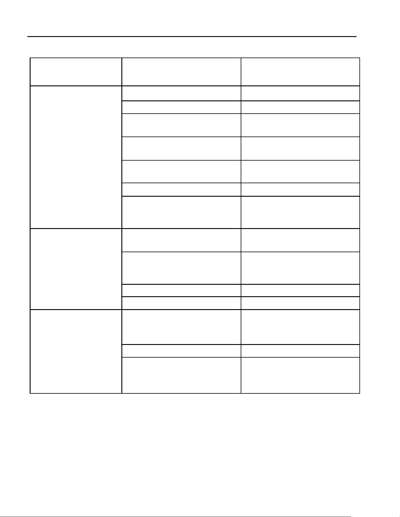
Hussong Mfg. Co, Inc. 71 Rev. 10 - November 2023
SP-34, PFS Report No. 19-553 Starng Serial Number: 23 86710 49
Issue Cause Soluon
Pilot and burner exnguish
while in operaon
No propane in tank Check propane tank. Rell if necessary.
Incorrect glass frame assembly installaon Refer to Secon 8.1 Glass Frame Assembly.
Improper pitch on horizontal venng 1/4” (6mm) rise per 12” (30mm) horizontal
pipe is required.
Defecve thermopile or thermocouple Check thermopile and thermocouple for
proper millivolts.
Inner vent pipe leaking exhaust gas back
into the rebox
Check for leaks and repair if necessary.
Vent cap blockage Remove debris if necessary
Excessive dra A restrictor plate may need to be installed
or modied, Refer to Secon 12.3.3 Vent
Restricon (Aer Installaon).
Glass Soong Improper log placement Refer to Secon 8.4 #SP34-50A Log Set
Installaon.
Improper venturi seng Venturi may need to be opened slightly to
allow more air into gas mix. Refer to Sec-
on 12.3.1 Burner Venturi.
Incorrect vent cap installaon Adjust if necessary.
Vent cap blockage Remove debris if necessary.
Improper venturi seng Venturi may need to be opened slightly to
allow more air into the gas mix. Refer to
Secon 12.3.1 Burner Venturi.
Flame burns blue and lis o
burner
Incorrect vent cap installaon Adjust if necessary.
Blockage or leakage of the vent system Check the vent pipe for leaks, and the vent
cap for debris. Repair vent pipe or remove
debris from vent cap if necessary.

Hussong Mfg. Co, Inc. 72 Rev. 10 - November 2023
SP-34, PFS Report No. 19-553 Starng Serial Number: 23 86710 49
14.0 Maintenance
ATTENTION: Installaon and repair should only done by a
qualied service person. The appliance should be inspect-
ed before use and at least annually by a professional ser-
vice person. More frequent cleaning might be required
due to excessive lint from carpeng, bedding material, et
cetera. It is imperave that control compartments, burn-
ers, and circulang air passageways of the appliance be
kept clean. Use a vacuum to clean all components.
WARNING: The appliance area must be kept clear and free
from combusble materials, gasoline and other amma-
ble vapors and liquids.
14.1 Firebox
Performed by: Qualied Service Person
Frequency: Annually
Acon:
• Vacuum and clean any debris in the rebox that is not
supposed to be there.
• Inspect and operate the boom latch assembly. Verify
the assembly is free from obstrucon to operate. The
handles must have spring tension but be able to move
forward freely
14.2 Fan (if applicable)
CAUTION: Label all wires prior to disconnecon when ser-
vicing controls. Wiring errors can cause improper and dan-
gerous operaon. Verify proper operaon aer servicing.
Performed by: Qualied Service Person
Frequency: Annually
Acon:
• Disconnect the fan from electrical current and vacuum.
• The bearings are sealed and require no oiling.
14.2.1 Fan Kit Removal
Disconnect electrical power.
Remove the safety barrier screen and glass valance.
Remove oponal panel set and log set.
Remove the control board - refer to Secon 8.5. As you
remove the control board disconnect the fan kit wiring
from the control module
Aer the control board is removed you can reach
through the control board opening to remove the fan
kit to the boom of the replace.
Remove the fan kit and service.
Reinstall in reverse order. Reinstall all previously re-
moved components
14.3 Vent System
NOTE: If the vent-air intake system is disassembled for any
reason, reinstall per instrucons provided with installaon.
For natural dra vent installaon, refer to secon 7.0, VENT-
ING.
Performed by: Qualied Service Person
Frequency: Annually
Acon:
• Examinaon of the vent system is required.
• Inspect the condion of vent and vent terminal for
soong or obstrucon and correct if present.
• The ow of combuson and venlaon air must not be
obstructed.
14.4 Glass Assembly
CAUTION: Do not operate appliance with the glass assembly
removed, cracked, or broken. Use protecve gloves to handle
any broken or damaged glass assembly components.
WARNING: Do not use substute materials.
WARNING: Avoid striking or slamming glass assembly. Avoid
abrasive cleaner. DO NOT clean glass while it is hot.
IMPORTANT: Any safety screen, guard, or barrier removed for
servicing the appliance must be replaced prior to operang
the appliance.
Performed by: Homeowner
Frequency: Annually
Acon:
• Prepare a work area large enough to accommodate the
glass assembly on a at, stable surface.
• Remove safety screen and glass frame assembly.
• Clean glass window with a suitable replace glass cleaner
using a so cloth. Abrasive cleaners must not be used. Be
careful not to scratch the glass when cleaning.
• Reinstall glass assembly and safety screen. Do not oper-
ate replace without safety screen.
Performed by: Qualied Service Person
Frequency: Annually
Acon:
• Clean glass window with a suitable replace glass cleaner
using a so cloth. Abrasive cleaners must not be used. Be
careful not to scratch the glass when cleaning.
• Inspect the glass for cracks, scratches, and nicks.
• Verify the glass assembly is properly intact and not dam-
aged.
• Replace the glass and the assembly #701-016T as neces-
sary.
• Only Hussong Mfg. Co., Inc. will supply the replacement
of glass assembly as a complete unit.
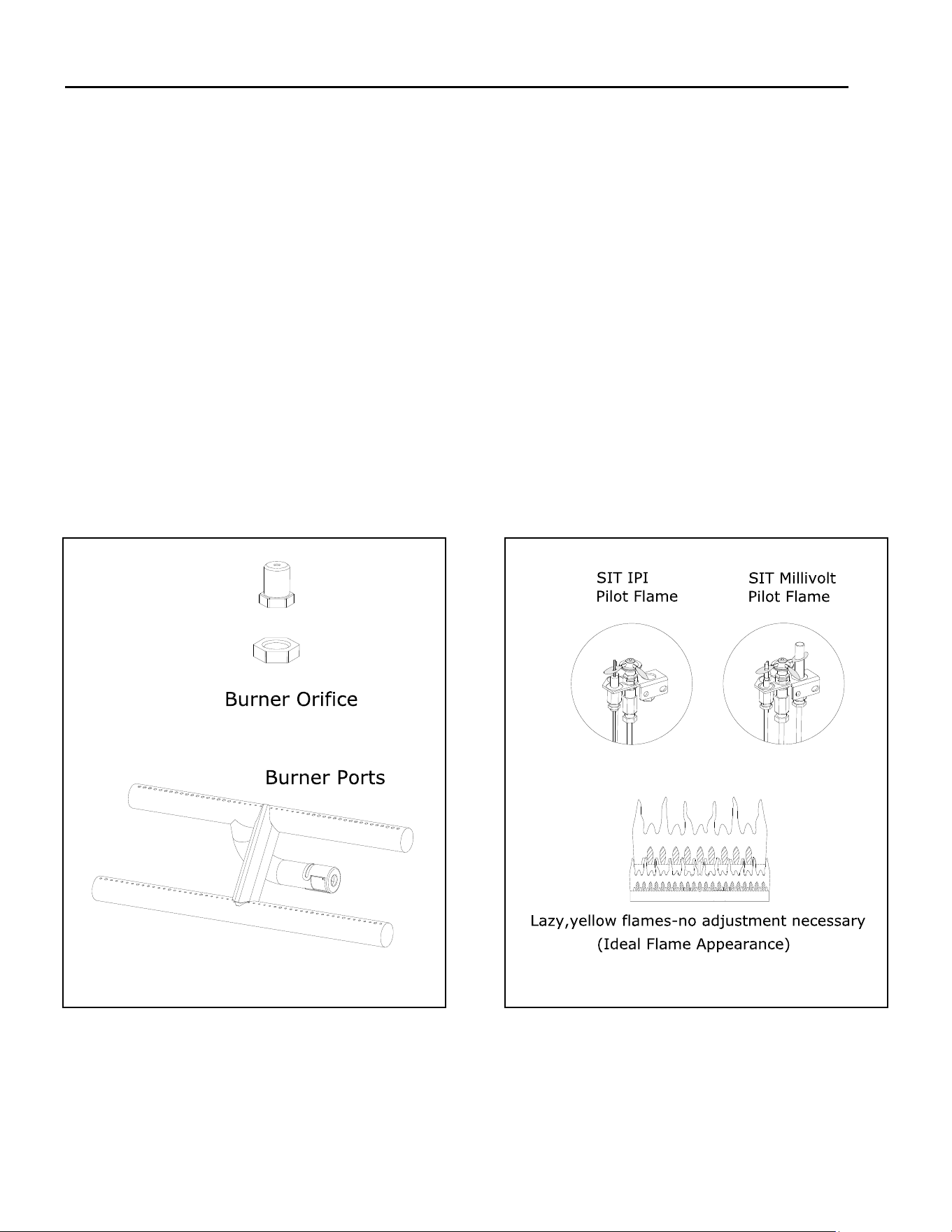
Hussong Mfg. Co, Inc. 73 Rev. 10 - November 2023
SP-34, PFS Report No. 19-553 Starng Serial Number: 23 86710 49
14.5 Burner and Pilot System
The burner assembly may be removed for easier access to the control compartment. See Secon 8.5 Control Board Removal
and Installaon for instrucons.
Verify gas supply is turned on and lled. Consult with plumber or gas supplier as necessary.
Performed by: Qualied Service Person
Frequency: Annually
Acon:
• Vacuum all components of the burner system.
• Check all accessible gas-carrying tubes, connecons, pipes and other components for leaks.
• Inspect the operaon of the ame safety system Pilot or Flame reccaon device. Visually check pilot light when in op-
eraon.
• Inspect and ensure the lighng of the main burner occurs within (4) seconds of the main gas valve opening. Check for
faulty or incorrect wiring and correct or replace as necessary. Inspect primary air openings (burner ports) for blockage,
especially near the pilot.
• Visually check burner ame paern when in operaon. Flames should be steady, not liing or oang.
• Test and measure the ame failure response me of the ame safety system. It must de-energize the safety shuto in no
more than (30) seconds.
Figure 14.1 - Burner System Figure 14.2 - Correct pilot / burner ame appearance
Hussong Mfg. Co, Inc. 74 Rev. 10 - November 2023
SP-34, PFS Report No. 19-553 Starng Serial Number: 23 86710 49
Replacement parts are available through your local dealer. Contact your local
dealer for availability and pricing. The following warning is for replacement
parts for this appliance.
⚠ WARNING: This product can expose you to chemicals including Lead,
which is [are] known to the State of California to cause cancer, birth defects
or other reproducve harm. For more informaon, visit
www.P65Warnings.ca.gov.
15.0 Replacement Parts List
SP-34-L Control Board and Parts
S.I.T. Complete Board Assembly -
Natural Gas
SP34L-130
S.I.T. Conversion Kit - Natural Gas NCK-SP34L-S30
S.I.T. Complete Board Assembly -
Propane
SP34L-131
S.I.T. Conversion Kit - Propane LCK-SP34L-S30
S.I.T. IPI Gas Valve - Natural Gas 700-660
Natural Gas - Valve Stepper Motor
(30% Turndown)
700-503
S.I.T. IPI Gas Valve - Propane 700-660-1
Propane - Valve Stepper Motor (30%
turndown)
700-503-1
Proame 2 IFC Module 700-652
S.I.T. IPI Pilot Assembly - Natural Gas 700-551
IFC Wire Harness Assembly 700-653
S.I.T. IPI Pilot Assembly - Propane 700-551-1
Main Line Wire Harness 700-654
Burner Orice - #46 - Natural Gas 700-246
ON/OFF Wire Harness 700-656
Burner Orice - #55 - Propane 700-255
Fan Receptacle / Light Kit Wire
Harness
700-657
18” Black Flex Tube 700-213B
Pilot Orice - Natural Gas #62 700-166
7” Flare x Brazed Fing 700-223F
Pilot Orice - Propane #35 700-168
Burner Tube SP34-351A
S.I.T. Transmier (Remote Control) 700-408
Pilot Shield SP34-043A
SIT IPI Pilot Hood 700-598
P.O. BOX 557 204 INDUSTRIAL PARK DRIVE
LAKEFIELD, MINNESOTA USA 56150-0577
Hussong Mfg. Co, Inc. 75 Rev. 10 - November 2023
SP-34, PFS Report No. 19-553 Starng Serial Number: 23 86710 49
SP-34-MV Control Board and Parts
S.I.T. Complete Board Assembly -
Natural Gas
SP34-770A
Pilot Orice - Natural Gas 700-165
S.I.T. Complete Board Assembly -
Propane
SP34-771A
Pilot Orice - Propane 700-095
S.I.T. MV Gas Valve - Natural Gas 700-086N
SIT Millivolt Pilot Hood 700-098
S.I.T. MV Gas Valve - Natural Gas (7-
day meout)
700-086N-7
SIT Millivolt Quick Change Screw 900-QCS
S.I.T. MV Gas Valve - Propane 700-087A
18” Flexible Gas Line - Black 700-213B
S.I.T. MV Gas Valve - Propane (7-day
meout)
700-087A-7
Flexible Gas Line - Valve to Burner
Connecon
700-226F
ON/OFF Rocker Switch 700-023
Natural Gas Burner Orice #46 700-246
S.I.T. Pilot Assembly - Natural Gas 700-088
Propane Burner Orice #55 700-255
S.I.T. Pilot Assembly - Propane 700-089
Conversion Kit - Natural Gas OCK-S46A
Push Buon Ignitor 700-032
Conversion Kit - Propane OCK-S55A
Flexible Pilot Tubing 700-091
Burner Tube SP34-351A
Millivolt Generator 700-092
Pilot Shield SP34-043A
Thermocouple 700-093
Hussong Mfg. Co, Inc. 76 Rev. 10 - November 2023
SP-34, PFS Report No. 19-553 Starng Serial Number: 23 86710 49
Glass and Glass Parts
Glass with Gasket - 30” x 20 1/2” 701-016T
1 1/8” Glass Gasket with Adhesive 900-006
Replacement Valance SP34-005
Safety Barrier
31” x 21.875” Safety Screen (with
brackets)
SP34-ES2
Addional Components
4” (102mm) Restrictor Plate 900-085
Manual Gas Shut-o Valve 700-203
Upper Hood SP34-200
Component Access Cover SP34-201
Vent Heat Shield Assembly SP34-HHS
Fan Kit
Fan Kit (SP34-L) (Standard) SP-028-IPI
Fan Kit (SP34-MV) (Oponal) SP-028
Log Set
6 Piece Log Set SP34-50A
Log #1 SP34-1A
Log #2 SP34-2A
Log #3 SP34-3A
Log #4 SP34-4A
Log #5 SP34-5A
Log #6 SP34-6A
1/2” Lava Rock 600-702
Rock Wool Embers 900-REMB
Safety Barrier Overlays
Prairie Design Overlay SP34-POL
Arched Prairie Design Overlay SP34-APOL

Hussong Mfg. Co, Inc. 77 Rev. 10 - November 2023
SP-34, PFS Report No. 19-553 Starng Serial Number: 23 86710 49
Limited Lifeme Warranty
Warranty Coverage
Hussong Manufacturing Company, Inc. (Hussong Mfg.)
warrants this Kozy Heat gas appliance from the date of
purchase to the original purchaser, that it is free of defects
in materials and workmanship at the me of manufacture.
Registering your replace warranty does not require any
documents to be sent in to Hussong Mfg. Please retain
your proof of purchase reecng the date of purchase
along with the serial number and model of your replace
for any future warranty claims.
If a defect is noted within the warranty period, the cus-
tomer should contact their authorized dealer for service
within 30 days.
30 Days: Parts & Labor*
• Paint
• Light bulbs
• Gasket material
• Glass media and media dam
Year 1: Parts & Labor*
All parts and material except the items listed in the 30 day
warranty and any exclusions or limitaons that may apply
*Hussong Mfg. will issue labor reimbursement to an author-
ized dealer only. Hussong Mfg. will not be liable for charges
occurred as a result of any service performed by a non-
authorized service provider, without pre-authorizaon.
Years 2 through Lifeme: Parts Only
• Firebox
• Heat Exchanger
• Logs
• Burner tube or pan
• Outer shell
• Heat shield(s)
• Front Viewing Glass (thermal shock only)
• Refractory Firebox liner (excluding enamel and glass pan-
els)
EXCLUSIONS AND LIMITATIONS
1. This appliance must be installed by a licensed, authorized service technician or contractor. It must be installed, operated
and maintained at all mes in accordance with the instrucons in the owner’s manual or the warranty is void.
2. This warranty is nontransferable and is made to the original purchaser only.
3. This warranty excludes standard wear and tear of the appliance which is considered normal usage over me.
4. Discoloraon and some minor expansion, contracon or movement of certain parts, resulng in noise, is normal and not a
defect.
5. Warranty is automacally voided if the appliance’s serial number and/or tesng label is removed or if the appliance is al-
tered or tampered with in any way.
6. Warranty is void if the appliance is subject to submersion in water or prolonged periods of dampness or condensaon. Any
damage to any part of the appliance due to water or weather damage which is the result of, but not limited to, improper
chimney/venng installaon will also render this warranty void.
7. This warranty does not cover installaon and operaonal related problems such as environmental condions, nearby
trees, buildings, hilltops, mountains, inadequate venng or venlaon, excessive osets, negave air pressures caused by
any mechanical systems.
8. Chimney components and other Non-Hussong Mfg. accessories used in conjuncon with the installaon of this appliance
are not covered under this warranty.
9. Damage to plated surfaces or accessories, if applicable, caused by scratches, ngerprints, melted items or other external
sources le on the surfaces from the use of cleaners is not covered under this warranty.

Hussong Mfg. Co, Inc. 78 Rev. 10 - November 2023
SP-34, PFS Report No. 19-553 Starng Serial Number: 23 86710 49
Limited Lifeme Warranty
EXCLUSIONS AND LIMITATIONS (connued)
10. It is expressly agreed and understood that this warranty is Hussong Mfg.’s sole obligaon and purchaser’s exclusive reme-
dy for defecve replace equipment. Hussong Mfg. is free of liability for any damages caused by this appliance, as well as
inconvenience expenses
and materials. Incidental or consequenal damages are not covered by this warranty. In some states, the exclusion of
incidental or consequenal damage may not apply. Hussong Mfg. shall not be held to implied warranes and this warran-
ty shall replace all previous warranes.
11. This limited lifeme warranty is the only warranty supplied by Hussong Mfg. Any warranes extended to the purchaser
by the dealer/distributor, whether expressed or implied, are hereby disclaimed and the purchaser’s recourse is expressly
limited to the warranes set forth herein.
12. Any part repaired or replaced during the limited warranty period will be warranted under the terms of the limited war-
ranty for a period not to exceed the remaining term of the original limited warranty.
13. Any replacement part repaired aer the warranty period will include a 90 day parts coverage
14. Hussong Mfg. may require the defecve part to be returned using a pre-authorized RGA number or a photo of the defec-
ve component. Failure to provide either can result in a denied claim.
15. This warranty does not cover the appliances ability to heat a desired space, as there are many factors that can impact the
heang performance in each home. Consideraon should be implied to the appliance’s locaon, room size, home design,
environmental condions, insulaon, and ghtness of the home.
16. Hussong Mfg. reserves the right to make changes at any me, without noce, in design, material, specicaons, and price
es. Hussong Mfg. reserves the right to disconnue models and products.
July 2018