Loading ...
Loading ...
Loading ...
7
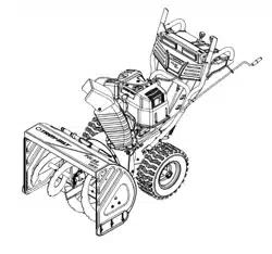
Routing Chute Tilt Cables
• If not already routed, slip the cables that run from
beneath the handle panel to the chute assembly
through the cable guide located on top of the
engine housing. See Figure 6.
Figure 6
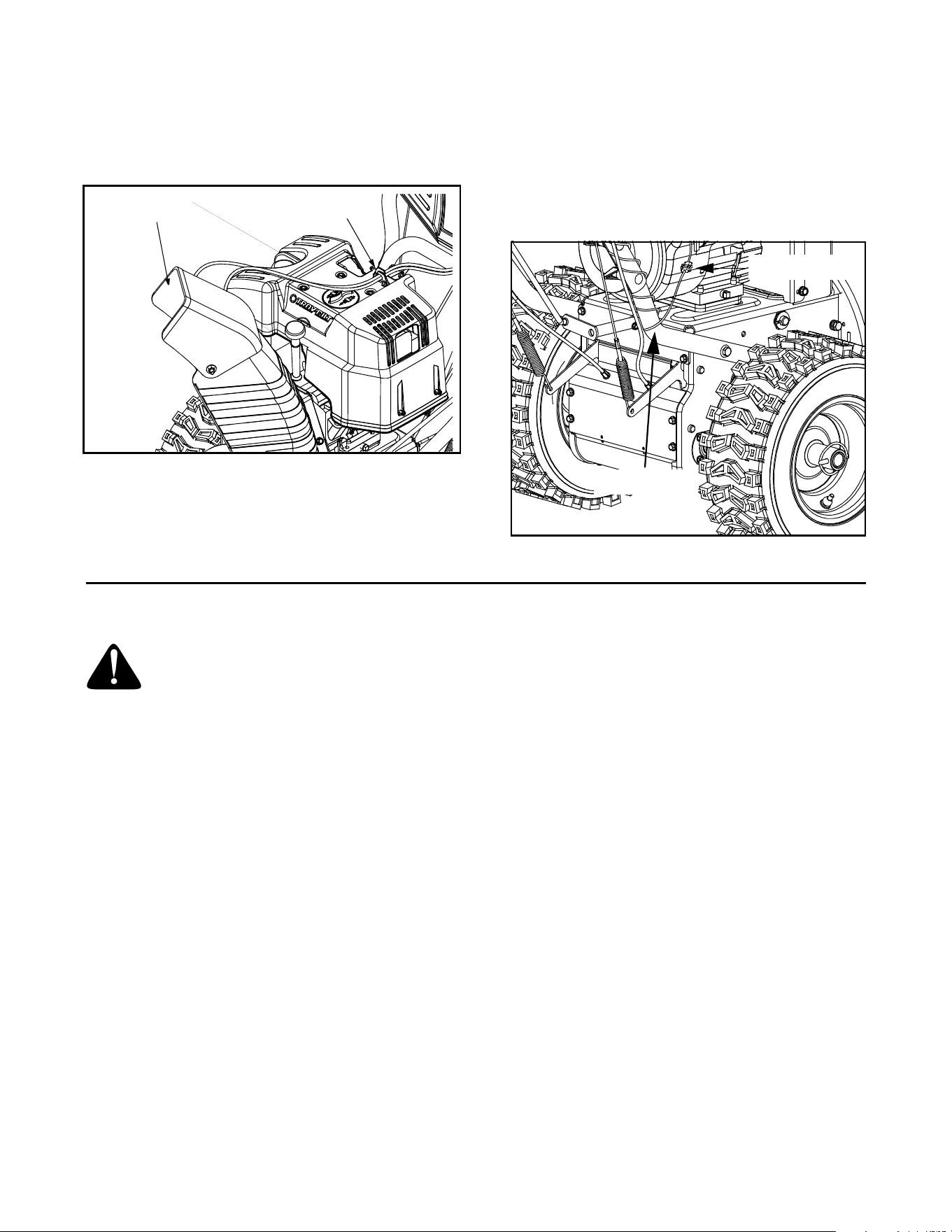
Connecting Alternator Lead
• If not already routed, unwrap the headlight wire
which is attached to the headlights, beneath the
handle panel. Wind the wire around the lower right
handle until excess slack is removed.
• Plug the wire from the headlight into the alternator
lead located on the right side of the engine,
beneath the fuel tank. See Figure 7.
Figure 7
SECTION 3: KNOW YOUR SNOW THROWER
WARNING: Read, understand, and follow
all instructions and warnings on the machine
and in this manual before operating.
Throttle Control
The throttle control is located on the engine. It regulates
the speed of the engine and also stops the engine. See
Figure 8.
Fuel Shut-Off Valve (Optional Equipment)
On models so equipped, the fuel shut-off valve, located
under fuel tank, controls fuel-flow from the fuel tank to
the engine. See Figure 8.
Safety Ignition Key
The ignition key must be inserted and snapped in place
in order for the engine to start. Remove the ignition key
to prevent unauthorized use of equipment.Do NOT
“turn” the ignition key in an attempt to start the engine.
Skid Shoes
The space between the shave plate and the ground can
be adjusted by positioning the skid shoes. Refer to Skid
Shoe Adjustment on page 13.
Shift Lever
The shift lever is located in the center of the handle
panel and is used to determine ground speed and
direction of travel. It can be moved into any of eight
positions. See Figure 8.
IMPORTANT:
Always release drive control before
changing speeds.
Forward
Your snow thrower has six forward (F) speeds, with
position number one (1) being the slowest speed.
Reverse
Your snow thrower has two reverse (R) speeds,
with position number one (1) being the slower
speed.
Drive Control / Auger Control Lock
The drive control is located on the right handle.
Squeeze the drive control to engage the wheel drive.
Release to stop. See Figure 8.
The drive control also locks the auger control, so you
can operate the chute directional control without
interrupting the snow throwing process. If the auger
control is engaged simultaneously with the drive
control, the operator can release the auger control (on
the left handle) and the augers will remain engaged.
Release both controls to stop the augers and wheel
drive.
IMPORTANT:
ALWAYS release the drive control before
moving the shift lever. Failure to do so will result in
premature wear to the drive system’s friction wheel.
Cable Guide
Discharge Chute
Lamp Wire
Alternator Lead
Loading ...
Loading ...
Loading ...