Loading ...
Loading ...
Loading ...
15
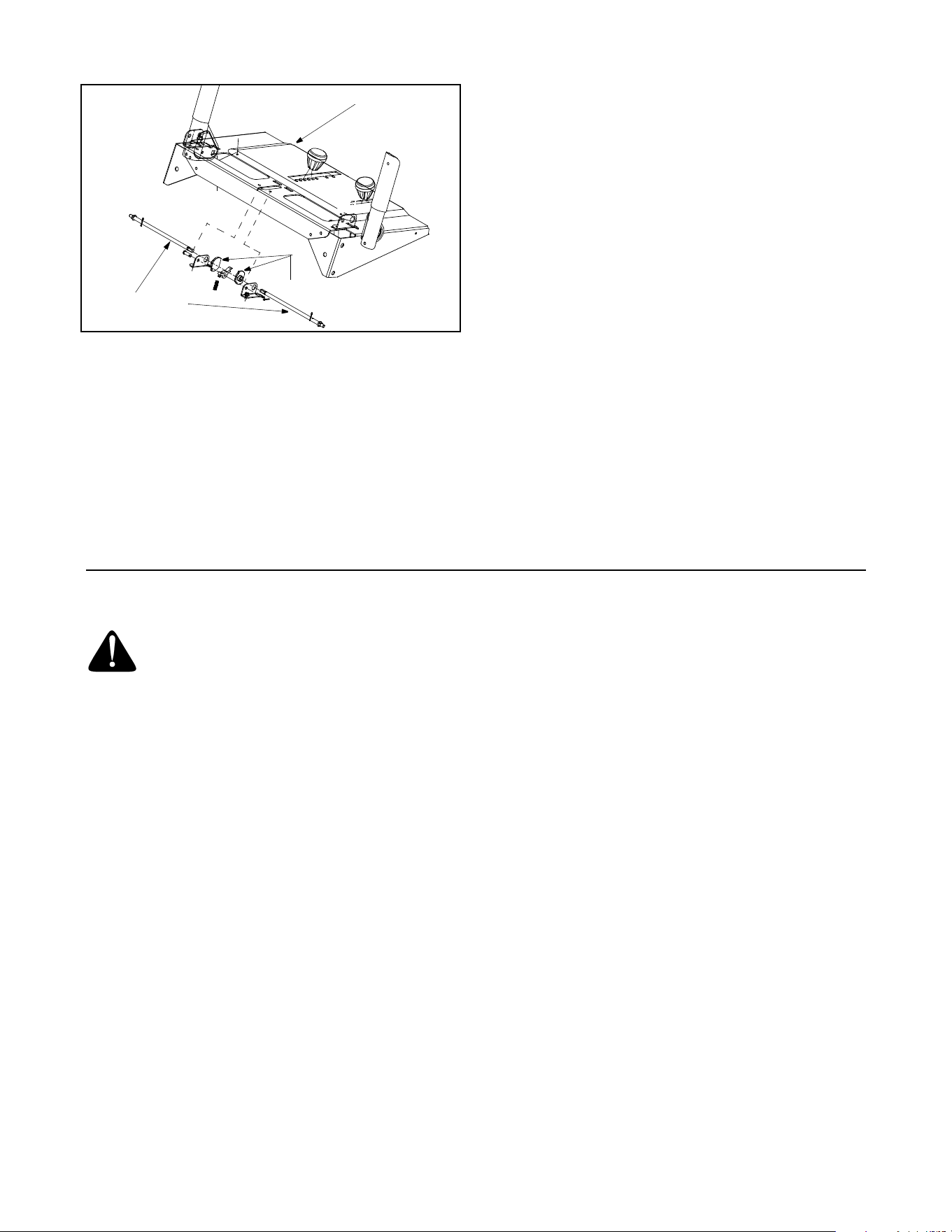
Figure 16
IMPORTANT:
Be careful not to allow grease to get on the
drive plate or friction wheel.
Drive Control / Auger Control Lock
The cams on the ends of the control rods which
interlock the drive and auger controls must be
lubricated at least once a season or every 25 hours of
operation using a multi-purpose automotive grease.
The cams can be accessed beneath the handle panel.
See Figure 16.
Engine
Refer to the separate engine manual packed with your
unit for all engine lubrication instructions.
Bonded Friction Wheel
Follow the instructions below to check the condition of
the bonded friction wheel every 25 hours of operation.
• Remove the six self-tapping screws from the frame
cover underneath the snow thrower.
• Visually inspect the bonded friction wheel for
excessive wear, cracks, or loose fit on the friction
wheel drive hub.
• Also engage the drive control and check if the
friction wheel is making contact with the friction
plate. Refer to Figure 11.
• If it does not make contact, adjust the drive cable
and recheck the friction wheel.
• Replace bonded friction wheel if necessary. Refer
to instructions in Service Section on Page 17.
SECTION 7: SERVICING YOUR SNOW THROWER
WARNING: Before servicing, repairing, or
inspecting, disengage all controls and stop
engine. Wait until all moving parts have come
to a complete stop. Disconnect spark plug
wire and ground it against the engine to
prevent unintended starting. Always wear
safety glasses during operation or while
performing any adjustments or repairs.
Augers
The augers are secured to the spiral shaft with two
shear bolts and flange lock nuts. If you hit a foreign
object or ice jam, the snow thrower is designed so that
the bolts may shear. See Figure 17.
If the augers do not turn, check if the bolts have
sheared. Two replacement shear bolts and flange lock
nuts have been provided with the snow thrower. Refer
to Hardware Pack on page 5.
IMPORTANT:
NEVER replace the auger shear bolts with
standard hex bolts. Any damage to the auger gearbox
or other components, as a result of doing so, will NOT
be covered by your snow thrower’s warranty.
Shave Plate and Skid Shoes
The shave plate and skid shoes on the bottom of the
snow thrower are subject to wear. They should be
checked periodically and replaced when necessary.
NOTE: The skid shoes on this machine have two wear
edges. When one side wears out, they can be rotated
180° to use the other edge.
• Remove the six carriage bolts (three per side), and
flange lock nuts which secure the skid shoes to the
snow thrower on either side. See .
• Reassemble new skid shoes with the hardware
removed earlier. Make certain the skid shoes are
adjusted to be level. Refer to .
• To remove the shave plate, remove the carriage
bolts, and flange lock nuts which secure the shave
plate to the snow thrower housing. See Figure 17.
Lube Cams Here
Handle Panel
Control Rods
Loading ...
Loading ...
Loading ...