Loading ...
Loading ...
Loading ...
5
SECTION 2: ASSEMBLING YOUR SNOW THROWER
NOTE: All references to right or left side of the snow
thrower are determined from behind the unit in the
operating position. The “operator’s position” is defined
as standing directly behind the snow thrower, facing the
handle panel.
Hardware Pack
Figure 1
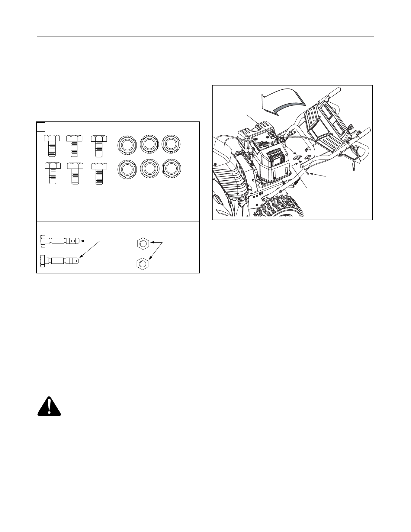
• The augers are secured to the auger shaft with two
shear bolts and flange lock nuts. If you hit a foreign
object or ice jam, the snow thrower is designed so
that the bolts may shear. Two replacement shear
bolts and nuts are provided for your convenience.
Store in a safe place until needed. See Figure 1.
IMPORTANT:
NEVER replace the auger shear bolts with
standard hex bolts. Any damage to the auger gearbox
or other components from standard hex bolts will not be
covered by your snow thrower’s warranty.
Assembling Handle
WARNING: Disconnect the spark plug
wire and ground it against the engine to
prevent unintended starting.
IMPORTANT:
Make any adjustments, as instructed on
Page 11, before operating your snow thrower. Failure
to follow these instructions may cause damage to the
snow thrower.
• Remove the lower plastic wing nut, cupped
washer, and carriage bolt from each side of the
lower handle. See Figure 2.
Figure 2
NOTE: Before proceeding, look at the lower rear of the
snow thrower frame to be sure the spring (found at the
end of each cable) is attached to its actuator bracket
See Figure 3.
• Pivot the upper handle assembly forward until it
locks over the lower handle. See Figure 2.
• Secure the upper handle and lower handle with the
two plastic wing nuts, bell washers and carriage
bolts previously removed from the lower hole.
• Firmly tighten all four wing nuts to secure the upper
handle to the lower handle.
• Slide the shift rod connector down over the end of
the lower shift rod. Tap the connector until it locks
over the lower shift rod. See Figure 3.
NOTE: If the connector is not properly assembled, the
shift rod will pivot and you will not be able to change
speeds or change directions.
Shear Bolts
Flange Lock
Nuts
B
A
ATTACHING THE CHUTE ASSEMBLY
Chute Flange Keepers
731-0851 (3) Not Shown
REPLACEMENT SHEAR BOLTS
Hex Screws
1/4-20 x 1.00”
(710-0597)
Flange Lock Nuts
1/4-20 Thread
(712-04064)
Wing Nut
Carriage Bolt
Bell Washer
Loading ...
Loading ...
Loading ...