
714 English Instruction Sheet
Page
1
®
714
Thermocouple Calibrator
Instruction Sheet
Introduction
The Fluke 714 Thermocouple Calibrator is a precise source and
measurement tool for calibrating thermocouple instruments. The
calibrator sources or measures in units of °C, °F, or mV, through
a thermocouple minijack.
Your calibrator is supplied with a Flex-Stand holster, an
installed 9 V alkaline battery, and this instruction sheet. Sets of
thermocouple miniplugs are available from Fluke. (Accessories
Fluke-700TC1 and Fluke-700TC2 TC Miniplug Kits.)
If the calibrator is damaged or something is missing, contact the
place of purchase immediately. Contact your Fluke distributor for
information about accessories. To order replacement parts or
spares, see “Replacement Parts.”
The following tables list the thermocouple types supported by the
calibrator, the standards and scales used for each type, the
thermocouple properties, and calibrator resolution. Full calibrator
specifications are listed at the end of this instruction sheet.
Note
Since mV input and output units are available, you can
use the calibrator for any thermocouple type by making
manual calculations or referring to tables.
PN 650306 July 1997 Rev. 1, 10/97
1997 Fluke Corporation. All rights reserved. Printed in U.S.A.
All product names are trademarks of their respective companies.
1.888.610.7664 sales@GlobalTestSupply.com
Fluke-Direct
.com
714 English Instruction Sheet
Page
2
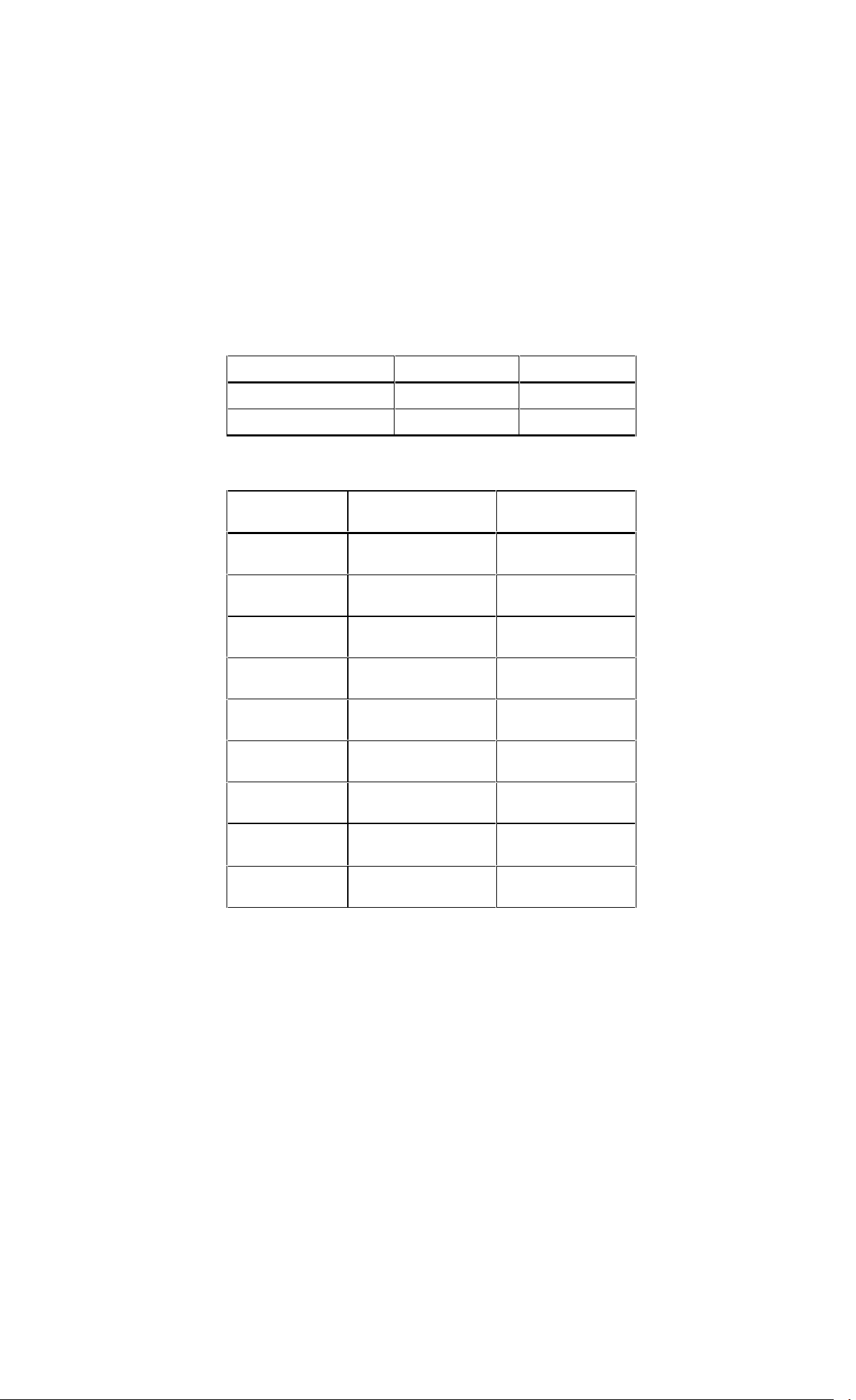
Thermocouple Standards and Scales
Thermocouple Type Standard Scale
J, K, T, E, R, S, B NIST 175 ITS-90
L (J-DIN), U (T-DIN) DIN 43710 IPTS-68
Thermocouple Properties
Thermocouple
Type
Temperature
Ranges
Display Resolution
J -200 to 1200°C,
-328 to 2192°F
0.1°C or °F
K -200 to 1370°C
-328 to 2498°F
0.1°C or °F
T -200 to 400°C
-328 to 752°F
0.1°C or °F
E -200 to 950°C
-328 to 1742°F
0.1°C or °F
R -20 to 1750°C
-4 to 3182°F
1°C or °F
S -20 to 1750°C
-4 to 3182°F
1°C or °F
B 600 to 1800°C
1112 to 3272°F
1°C or °F
L -200 to 900°C
-328 to 1652°F
0.1°C or °F
U -200 to 600°C
-328 to 1112°F
0.1°C or °F
1.888.610.7664 sales@GlobalTestSupply.com
Fluke-Direct
.com
714 English Instruction Sheet
Page
3
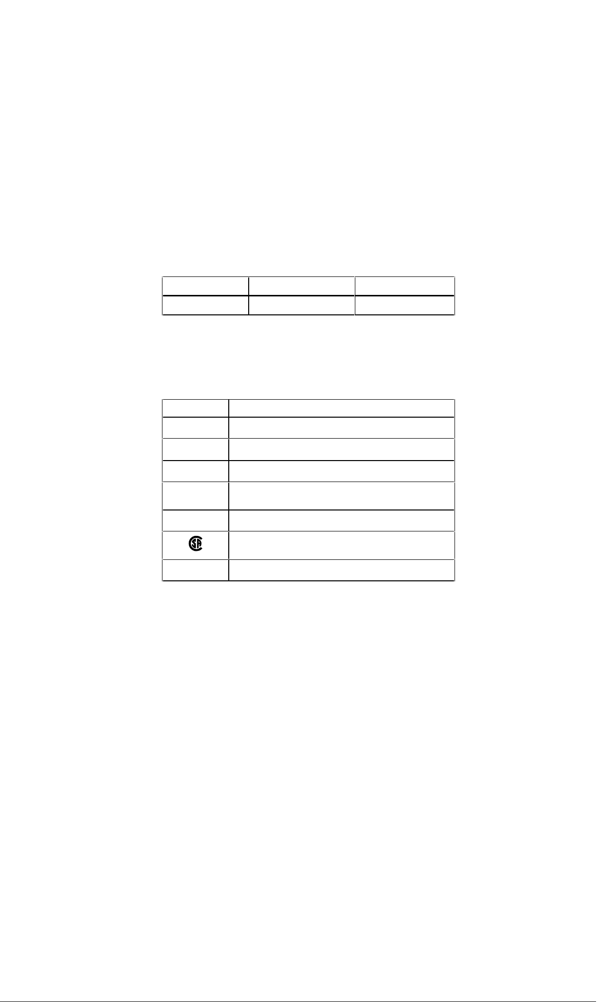
Millivolt Range and Resolution
Mode Range Display Resolution
mV -10 to 75 mV 0.01 mV
Explanation of International Symbols
The following symbols are used on the calibrator or in this
instruction sheet. The table below explains their meaning.
International Symbols
Symbol Meaning
J
Earth ground
I
Fuse
M
Battery
W
Refer to this instruction sheet for information about
this feature.
T
Double insulated
Conforms to relevant Canadian Standards
Association directives.
P
Conforms to European Union directives
1.888.610.7664 sales@GlobalTestSupply.com
Fluke-Direct
.com

714 English Instruction Sheet
Page
4
Safety Information
W Warning
To avoid possible electric shock or personal injury:
• Never apply more than 30 V between the TC
terminals, or between either TC terminal and
earth ground.
• Make sure the battery door is closed and
latched before you operate the calibrator.
• Remove an attached thermocouple miniplug
from the calibrator before you open the battery
door.
• Do not operate the calibrator if it is damaged.
• Do not operate the calibrator around explosive
gas, vapor, or dust.
When servicing the calibrator, use only specified replacement
parts.
Turning the Calibrator On
Press the green O pushbutton to turn the calibrator on and off.
1.888.610.7664 sales@GlobalTestSupply.com
Fluke-Direct
.com
714 English Instruction Sheet
Page
5
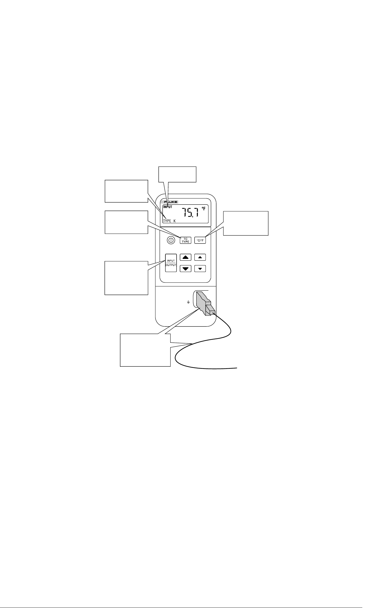
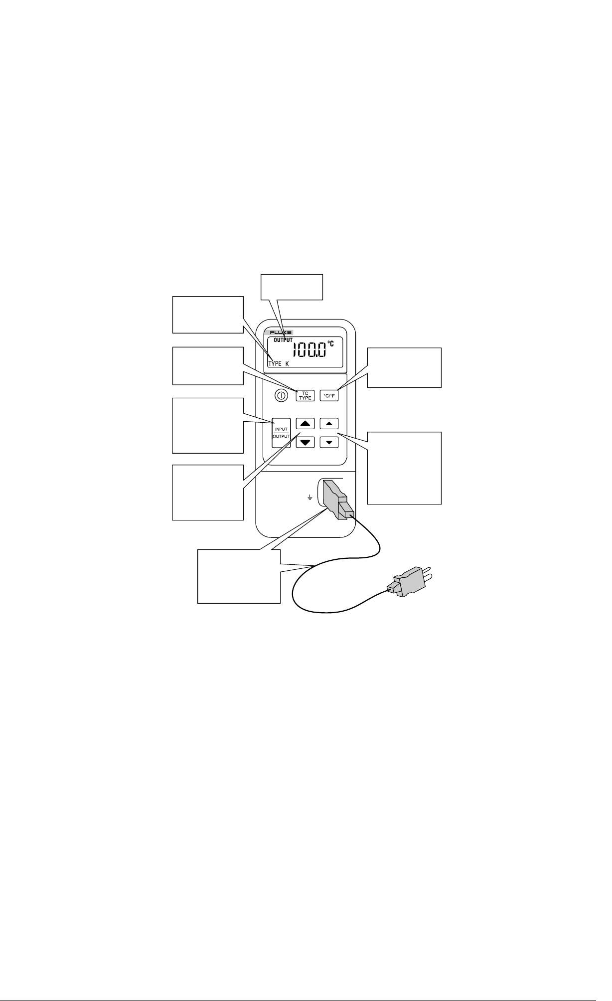
Measuring a Thermocouple
714
THERMOCOUPLE
CALIBRATOR
TC
30V
MAX
Press to toggle
°C or °F
Press so that
INPUT is on
the display
Shows TC type
selected
INPUT
TC wire and
miniplug of same
type as selected
Press to select
TC type or mV
ke01f.eps
1.888.610.7664 sales@GlobalTestSupply.com
Fluke-Direct
.com
714 English Instruction Sheet
Page
6
Simulating a Thermocouple
714
THERMOCOUPLE
CALIBRATOR
TC
30V
MAX
Press to toggle
°C or °F
TC wire and
miniplug of same
type as selected
Press so that
OUTPUT is on
the display
Press to scroll
up/down 0.1°
(or 0.01 mV).
Hold down to
scroll faster
Press to step
up/down 50°
(or 10 mV)
Press to select
TC type or mV
Shows TC type
selected
OUTPUT
ke02f.eps
1.888.610.7664 sales@GlobalTestSupply.com
Fluke-Direct
.com

714 English Instruction Sheet
Page
7
Maintenance
For maintenance procedures not described in this sheet, contact
a Fluke Service Center.
In Case of Difficulty
• Check the battery and thermocouple test wiring. Replace as
necessary.
• Review this sheet to make sure you are using the calibrator
correctly.
If the calibrator needs repair, contact a Fluke Service Center. If
the calibrator is under warranty, see the warranty statement for
terms. If the warranty has lapsed, the calibrator will be repaired
and returned for a fixed fee. Contact a Fluke Service Center for
information and price.
Cleaning
Periodically wipe the case with a damp cloth and detergent; do
not use abrasives or solvents.
Calibration
Calibrate your calibrator once a year to ensure that it performs
according to its specifications. A calibration manual is available
(PN 686540). Call 1-800-526-4731 from the USA and Canada. In
other countries, contact a Fluke Service Center.
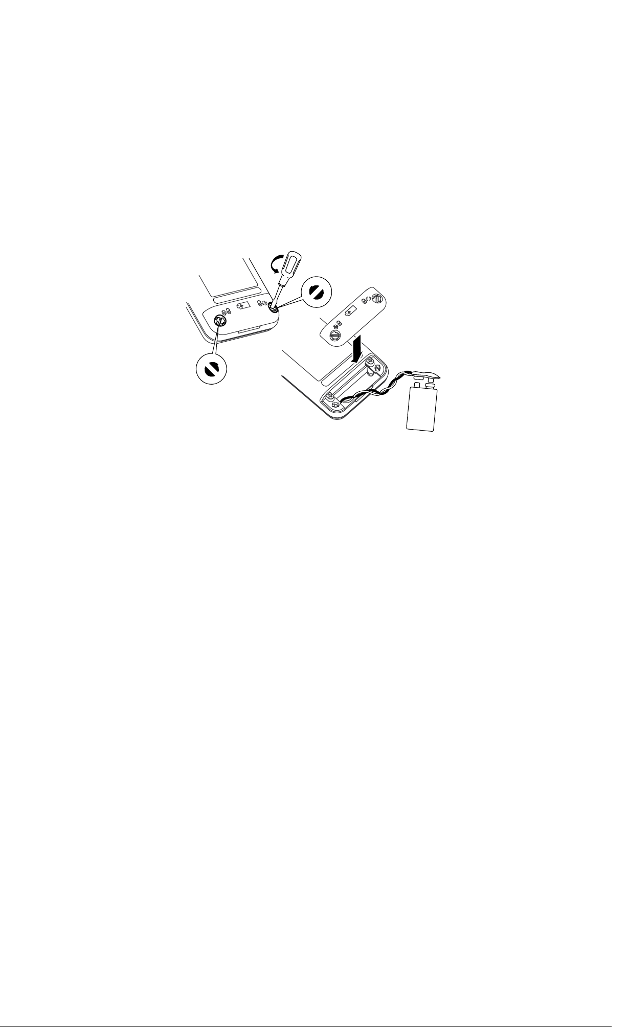
Replacing the Battery
When the M symbol appears on the display, replace the
battery with a 9 V alkaline battery.
1.888.610.7664 sales@GlobalTestSupply.com
Fluke-Direct
.com
714 English Instruction Sheet
Page
8
it07f.eps
Replacing the Fuse
! Warning
To avoid personal injury or damage to the
calibrator, use only a 0.125A 250V fast fuse,
Littelfuse
®
2AG.
Fuse F1 is probably blown if in the input mode, the calibrator
always reads OL, even with a thermocouple connected.
1.888.610.7664 sales@GlobalTestSupply.com
Fluke-Direct
.com

714 English Instruction Sheet
Page
9
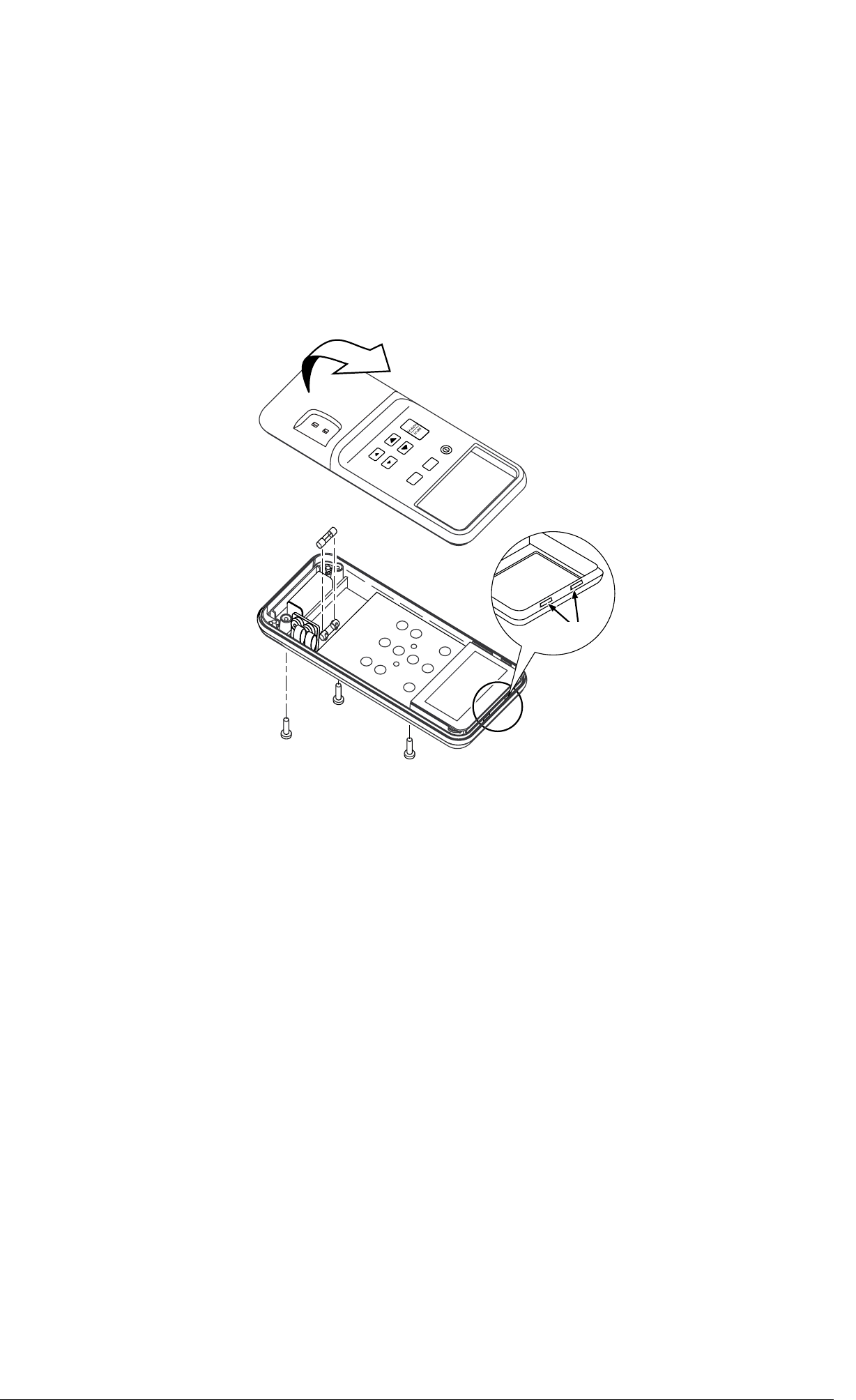
Replace the fuse as follows:
1. Remove the test leads and turn the calibrator off.
2. Remove the battery door.
3. Remove the three Phillips-head screws from the case
bottom and turn the case over.
4. Gently lift the top cover from the end nearest the input/output
terminals until it unsnaps from the bottom cover.
5. Replace the fuse with a 0.125 A 250 V fast fuse, Littelfuse
®
2AG.
6. Fit the top and bottom covers together, engaging the two
snaps. Make sure that the gasket is properly seated.
Reinstall the three screws.
7. Replace the battery door.
1.888.610.7664 sales@GlobalTestSupply.com
Fluke-Direct
.com
714 English Instruction Sheet
Page
10
F1
Snaps
ke03f.eps
1.888.610.7664 sales@GlobalTestSupply.com
Fluke-Direct
.com
714 English Instruction Sheet
Page
11
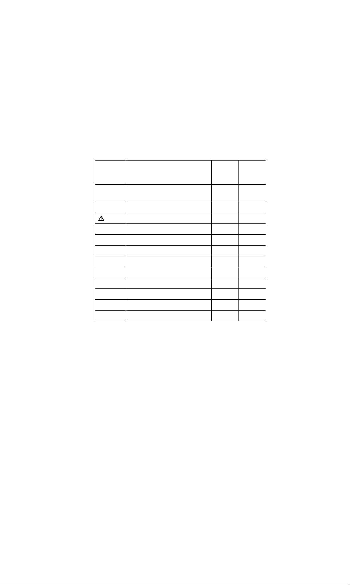
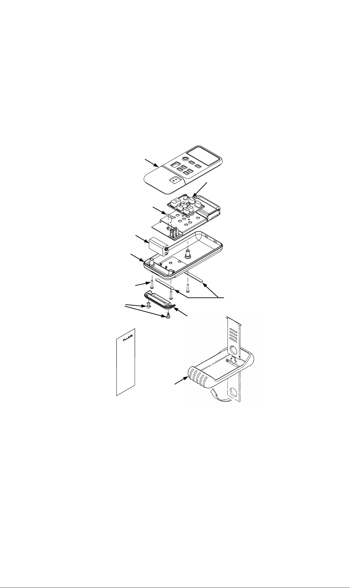
Replacement Parts and Accessories
Replacement Parts
Item Description PN or
Model
no.
Qty.
BT1 9V battery, ANSI/NEDA 1604A or
IEC 6LR61
614487 1
CG81Y Holster, Yellow CG81Y 1
!
F1 Fuse, 125 mA, 250V fast 686527 1
MP85 Case top 620234 1
MP86 Case bottom 620168 1
H2, 3, 4 Case screw 832246 3
MP89, 90 Non-skid foot 824466 2
MP92 Battery door 619947 1
H5, 6 Battery door fasteners 948609 2
S1 Keypad 687076 1
− 714 Instruction Sheet 560306 1
− 71X Series Calibration Manual 686540 Option
1.888.610.7664 sales@GlobalTestSupply.com
Fluke-Direct
.com
714 English Instruction Sheet
Page
12
F1
H2, 3, 4
BT1
H5, 6
MP85
MP86
Holster
S1
MP92
Instruction
Sheet
MP89, 90
ke04c.eps
1.888.610.7664 sales@GlobalTestSupply.com
Fluke-Direct
.com
714 English Instruction Sheet
Page
13
Specifications
Specifications are based on a one year calibration cycle and
apply for ambient temperature from +18°C to +28°C unless
stated otherwise. “Counts” means number of increments or
decrements of the least significant digit.
Temperature Measure and Thermocouple Simulate
TC Type Resolution Error Reference
Junction
Error
J, K, T, E, L, U 0.1°C or °F ±(0.3°C + 10 µV) ±0.2°C
B, R, S 1°C or °F ±(0.3°C + 10 µV) ±0.2°C
Maximum input voltage: 30 V
Millivolt Measure and Source
Range Resolution Accuracy
-10 mV to 75 mV 0.01 mV ±(0.025% + 1 count)
Maximum input voltage: 30 V
1.888.610.7664 sales@GlobalTestSupply.com
Fluke-Direct
.com

714 English Instruction Sheet
Page
14
General Specifications
Maximum voltage applied between any terminal and earth
ground or between any two terminals: 30 V
Storage temperature: -40°C to 60°C
Operating temperature: -10°C to 55°C
Operating altitude: 3000 meters maximum
Temperature coefficient: 0.05 x specified accuracy per °C for
temperature ranges -10°C to 18°C and 28°C to 55°C
Relative humidity: 95% up to 30°C, 75% up to 40°C, 45% up to
50°C, and 35% up to 55°C
Vibration: Random 2 g, 5 Hz to 500 Hz
Shock: 1 meter drop test
Safety: Certified as compliant to CAN/CSA C22.2 No.
1010.1:1992. Complies with ANSI/ISA S82.01-1994.
Power requirements: Single 9 V battery (ANSI/NEDA 1604A or
IEC 6LR61)
Size: 32 mm H x 87 mm W x 187 mm L (1.25 in H x 3.41 in W x
7.35 in L);
With holster and Flex-Stand: 52 mm H x 98 mm W x 201 mm L
(2.06 in H x 3.86 in W x 7.93 in L)
Weight: 332 g (11.7 oz);
With holster and Flex-Stand: 584 g (20.6 oz)
1.888.610.7664 sales@GlobalTestSupply.com
Fluke-Direct
.com

714 English Instruction Sheet
Page
15
LIMITED WARRANTY & LIMITATION OF LIABILITY
This Fluke product will be free from defects in material and workmanship
for three years from the date of purchase. This warranty does not cover
fuses, disposable batteries or damage from accident, neglect, misuse or
abnormal conditions of operation or handling. Resellers are not
authorized to extend any other warranty on Fluke’s behalf. To obtain
service during the warranty period, send your defective calibrator to the
nearest Fluke Authorized Service Center with a description of the
problem.
THIS WARRANTY IS YOUR ONLY REMEDY. NO OTHER
WARRANTIES, SUCH AS FITNESS FOR A PARTICULAR PURPOSE,
ARE EXPRESSED OR IMPLIED. FLUKE IS NOT LIABLE FOR ANY
SPECIAL, INDIRECT, INCIDENTAL OR CONSEQUENTIAL DAMAGES
OR LOSSES, ARISING FROM ANY CAUSE OR THEORY. Since some
states or countries do not allow the exclusion or limitation of an implied
warranty or of incidental or consequential damages, this limitation of
liability may not apply to you.
1.888.610.7664 sales@GlobalTestSupply.com
Fluke-Direct
.com
