
®
718Ex 30G/100G/300G
Pressure Calibrator
Users Manual
May 2004 Rev. 2, 5/09
© 2004-2009 Fluke Corporation. All rights reserved. Specifications are subject to change without notice.
All product names are trademarks of their respective companies.
1.888.610.7664 sales@GlobalTestSupply.com
Fluke-Direct
.com

LIMITED WARRANTY AND LIMITATION OF LIABILITY
Each Fluke product is warranted to be free from defects in material and workmanship under normal use and service. The warranty period is
three years (one year for pump assembly) and begins on the date of shipment. Parts, product repairs, and services are warranted for 90
days. This warranty extends only to the original buyer or end-user customer of a Fluke authorized reseller, and does not apply to fuses, dis-
posable batteries, or to any product which, in Fluke's opinion, has been misused, altered, neglected, contaminated, or damaged by accident
or abnormal conditions of operation or handling. Fluke warrants that software will operate substantially in accordance with its functional
specifications for 90 days and that it has been properly recorded on non-defective media. Fluke does not warrant that software will be error
free or operate without interruption.
Fluke authorized resellers shall extend this warranty on new and unused products to end-user customers only but have no authority to ex-
tend a greater or different warranty on behalf of Fluke. Warranty support is available only if product is purchased through a Fluke authorized
sales outlet or Buyer has paid the applicable international price. Fluke reserves the right to invoice Buyer for importation costs of re-
pair/replacement parts when product purchased in one country is submitted for repair in another country.
Fluke's warranty obligation is limited, at Fluke's option, to refund of the purchase price, free of charge repair, or replacement of a defective
product which is returned to a Fluke authorized service center within the warranty period.
To obtain warranty service, contact your nearest Fluke authorized service center to obtain return authorization information, then send the
product to that service center, with a description of the difficulty, postage and insurance prepaid (FOB Destination). Fluke assumes no risk
for damage in transit. Following warranty repair, the product will be returned to Buyer, transportation prepaid (FOB Destination). If Fluke
determines that failure was caused by neglect, misuse, contamination, alteration, accident, or abnormal condition of operation or handling,
including overvoltage failures caused by use outside the product’s specified rating, or normal wear and tear of mechanical components,
Fluke will provide an estimate of repair costs and obtain authorization before commencing the work. Following repair, the product will be
returned to the Buyer transportation prepaid and the Buyer will be billed for the repair and return transportation charges (FOB Shipping
Point).
THIS WARRANTY IS BUYER'S SOLE AND EXCLUSIVE REMEDY AND IS IN LIEU OF ALL OTHER WARRANTIES, EXPRESS OR IM-
PLIED, INCLUDING BUT NOT LIMITED TO ANY IMPLIED WARRANTY OF MERCHANTABILITY OR FITNESS FOR A PARTICULAR
PURPOSE. FLUKE SHALL NOT BE LIABLE FOR ANY SPECIAL, INDIRECT, INCIDENTAL, OR CONSEQUENTIAL DAMAGES OR
LOSSES, INCLUDING LOSS OF DATA, ARISING FROM ANY CAUSE OR THEORY.
Since some countries or states do not allow limitation of the term of an implied warranty, or exclusion or limitation of incidental or consequen-
tial damages, the limitations and exclusions of this warranty may not apply to every buyer. If any provision of this Warranty is held invalid or
unenforceable by a court or other decision-maker of competent jurisdiction, such holding will not affect the validity or enforceability of any
other provision.
1.888.610.7664 sales@GlobalTestSupply.com
Fluke-Direct
.com

i
Table of Contents
Title Page
Introduction..................................................................................................................... 1
How to Contact Fluke ..................................................................................................... 2
Safety Information .......................................................................................................... 2
Faults and Damage ................................................................................................... 7
Safety Regulations..................................................................................................... 8
Certification Information............................................................................................. 9
Getting Acquainted with the Calibrator ........................................................................... 9
Power Saver .............................................................................................................. 11
Zeroing with Absolute Pressure Modules ....................................................................... 11
Calibrating a P/I Transmitter........................................................................................... 13
Using the Internal Pump ............................................................................................ 13
Using an External Pump ............................................................................................ 17
External Fluke Pressure Module Compatibility ............................................................... 19
Cleaning the Pump Valve Assembly............................................................................... 20
Switch Test..................................................................................................................... 20
Maintenance................................................................................................................... 21
In Case of Difficulty.................................................................................................... 21
Cleaning .................................................................................................................... 22
1.888.610.7664 sales@GlobalTestSupply.com
Fluke-Direct
.com

718Ex 30G/100G/300G
Users Manual
ii
Calibration................................................................................................................. 22
Replacing the Battery................................................................................................ 22
Approved Batteries.................................................................................................... 23
Parts and Accessories ................................................................................................... 24
Specifications................................................................................................................. 25
Pressure Sensor Input .............................................................................................. 25
Pressure Sensor Range and Resolution ................................................................... 25
Pressure Module Input .............................................................................................. 26
DC mA Input ............................................................................................................. 26
General Specifications .............................................................................................. 26
Product Compliance Markings .................................................................................. 27
1.888.610.7664 sales@GlobalTestSupply.com
Fluke-Direct
.com

iii
List of Tables
Table Title Page
1. International Electrical Symbols .................................................................. 3
2. Pushbutton Functions.................................................................................. 10
3. Pump Features ............................................................................................ 12
4. Recommended Pressure Modules .............................................................. 17
5. Fluke Pressure Module Compatibility .......................................................... 19
6. Replacement Parts and Accessories........................................................... 24
1.888.610.7664 sales@GlobalTestSupply.com
Fluke-Direct
.com

v
List of Figures
Figure Title Page
1. Connection Technique................................................................................. 7
2. Front Panel Features................................................................................... 9
3. Pump Features ............................................................................................ 12
4. Internal Pressure Sensor with Internal Pump .............................................. 15
5. Pressure Module with Internal Pump........................................................... 16
6. Pressure Module with External Pump.......................................................... 18
7. Battery Replacement ................................................................................... 22
1.888.610.7664 sales@GlobalTestSupply.com
Fluke-Direct
.com

1
718Ex 30G/100G/300G
Pressure Calibrator
Introduction
XWWarning
Read Safety Information before using the
Calibrator.
The Fluke Model 718Ex 30G, 718Ex 100G, and 718Ex
300G Pressure Calibrators (hereafter called Calibrator)
can do the following:
Calibrate P/I (pressure to current) transmitters.
• Measure pressure via a 1/8-inch NPT pressure fitting
and an internal pressure sensor or via Fluke 700PEx
Series Pressure Modules.
• Measure current up to 24 mA.
• Simultaneously display pressure and current
measurements.
• Perform switch testing.
The Calibrator is for use ONLY in Ex-hazardous areas.
The Calibrator makes 5-digit pressure readings in the
following units: psi, inH
2
O at 4 °C, inH
2
O at 20 °C, kPa,
cmH
2
O at 4 °C, cmH
2
O at 20 °C, bar, mbar, kg/cm
2
, inHg,
and mmHg. Full-scale pressure sensor input is as follows:
• Model 718Ex 30G: 30 psi (206.85 kPa, 2.0685 bar).
OL appears at 33 psi.
• Model 718Ex 100G: 100 psi (689.5 kPa, 6.895 bar).
OL appears at 120 psi.
• Model 718EX 300G: 300 psi (2068 kPa, 20.68 bar).
OL appears at 360 psi.
The Calibrator measures pressure sensor inputs in the
units shown under Pressure Sensor Range and
Resolution.
For Pressure Modules, full-scale readings for all pressure
ranges can be made in psi, kPa, and inHg units. To avoid
display overflow, full-scale readings are limited to
1.888.610.7664 sales@GlobalTestSupply.com
Fluke-Direct
.com

718Ex 30G/100G/300G
Users Manual
2
1000 psi in cmH
2
O, mbar, and mmHg units, and 3000 psi
in inH
2
O units. Pressures of at least 15 psi must be
measured for meaningful readings in bar and kg/cm
2
units.
The Calibrator is supplied with:
• a holster
• one installed 9 V alkaline battery
• one set of TL75 test leads
• one set of AC72A alligator clips
• a Control Drawing
• a CD-Rom
If the Calibrator is damaged or something is missing,
contact the place of purchase immediately. Contact a
Fluke distributor for information about accessories. See
Contacting Fluke. To order replacement parts or spares,
see Parts and Accessories.
A Wa
rning identifies conditions and actions that pose
hazard(s) to the user; a Caution identifies conditions and
actions that may damage the Calibrator or the equipment
under test.
Safety and electrical symbols used in this manual and on
the Calibrator are displayed in Table 1.
1.888.610.7664 sales@GlobalTestSupply.com
Fluke-Direct
.com

Pressure Calibrator
Safety Information
3
Table 1. International Electrical Symbols
Symbol Meaning
+
Power ON/OFF
J
Earth ground
( Conforms to ATEX requirements.
M
Battery
X
Hazardous Voltage
W
Risk of Danger. Important information. Refer to manual.
T
Double insulated
)
Conforms to relevant Canadian and US Standards.
P
Conforms to relevant European Union directives.
f
Pressure
~
Do not dispose of this product as unsorted municipal waste. Go to Fluke’s website for recycling
information.
;
Conforms to relevant Australian standards.
1.888.610.7664 sales@GlobalTestSupply.com
Fluke-Direct
.com

718Ex 30G/100G/300G
Users Manual
4
XW Warning
To avoid electric shock, injury, or damage to the Calibrator:
• Use the Calibrator only as described in this User Manual and the Fluke 718Ex CCD (Concept Control
Drawing) or the protection provided by the Calibrator may be impaired.
• Inspect the Calibrator before use. Do not use it if it appears damaged.
• Check the test leads for continuity, damaged insulation, or exposed metal. Replace damaged test leads.
• When using probes, keep fingers behind the finger guards on the probes
• Never apply more than 30.0 V between the input terminals, or between any terminal and earth ground.
• Applying more than 30.0 V to the input terminals invalidates the Calibrator’s Ex Approval and may
result in permanent damage to the unit so it can no longer be used.
• Use the proper terminals, mode, and range for the measuring or sourcing application.
• To prevent damage to the unit under test, be sure the Calibrator is in the correct mode before
connecting the test leads.
• When making connections, connect the COM test probe before the live test probe. When
disconnecting, disconnect the live probe before the COM probe.
• Never use the Calibrator with the red holster removed.
• Never open the Calibrator case. Opening the case invalidates the Calibrator’s Ex Approval.
• Make sure the battery door is closed before using the Calibrator.
• Replace the battery as soon as the B (low battery) symbol appears to avoid false readings that can
lead to electric shock. Remove the Calibrator from the Ex-hazardous area before opening the battery
door.
1.888.610.7664 sales@GlobalTestSupply.com
Fluke-Direct
.com

Pressure Calibrator
Safety Information
5
• Remove test leads from the Calibrator before opening the battery door.
• This equipment is specified for use in measurement category I (CAT I) pollution degree 2 environments
and should not be used in CAT II, CAT III, or CAT IV environments. Voltage transients should not
exceed 300 volts for the CAT I applications where this product is used. Measurement transients are
defined in IEC1010-1 as 2 µs rise time with a 50 μs duration at 50 % of the maximum amplitude height.
• Measurement Category I (CAT I) is defined for measurements performed on circuits not directly
connected to the mains.
• Turn off circuit power before connecting the Calibrator mA and COM terminals in the circuit. Place
Calibrator in series with the circuit.
• When servicing the Calibrator, use only specified replacement parts. Do not open the Calibrator case.
Opening the case invalidates the Calibrator’s Ex Approval.
• Do not allow water inside the case.
• Do not use in a damp or wet environment.
• When using the Calibrator’s internal pressure sensor, do not connect a pressure module at the
Calibrator to avoid misleading readings. If both a pressure module and the internal pressure sensor are
connected, the Calibrator displays ONLY the pressure module measurement. To avoid misleading
readings, disconnect the pressure module connector at the Calibrator.
• To avoid a violent release of pressure in a pressurized system, shut off the valve and slowly bleed off
the pressure before attaching or detaching the internal pressure sensor or pressure module fitting to
the pressure line.
• To avoid overpressure damage, do not apply pressure to the internal pressure sensor input that
exceeds the following:
1.888.610.7664 sales@GlobalTestSupply.com
Fluke-Direct
.com

718Ex 30G/100G/300G
Users Manual
6
• Model 718Ex 30G: 30.000 psi, 206.85 kPa, or 2.0685 bar. OL appears at 33 psi.
• Model 718Ex 100G: 100.00 psi, 689.5 kPa, or 6.895 bar. OL appears at 120 psi.
• Model 718EX 300G: 300.00 psi, 2068 kPa, or 20.68 bar. OL appears at 360 psi.
• When measuring the pressure of potentially hazardous gases, care must be taken to minimize the
possibility of leakage:
• Confirm that all pressure connections are properly sealed.
• Confirm that the Pressure/Vacuum Release Control is in the closed position (fully clockwise) and
the Pressure/Vacuum switch is in the + position (fully clockwise).
• If the Calibrator has been dropped or subjected to rough handling, remove the Calibrator to a safe
area and check for leaks to confirm the integrity of the internal pneumatic components.
• Do not use a Model 718Ex (including 718Ex 300G) to measure potentially hazardous gases at pressure
greater than 100 psi (6.9 bar).
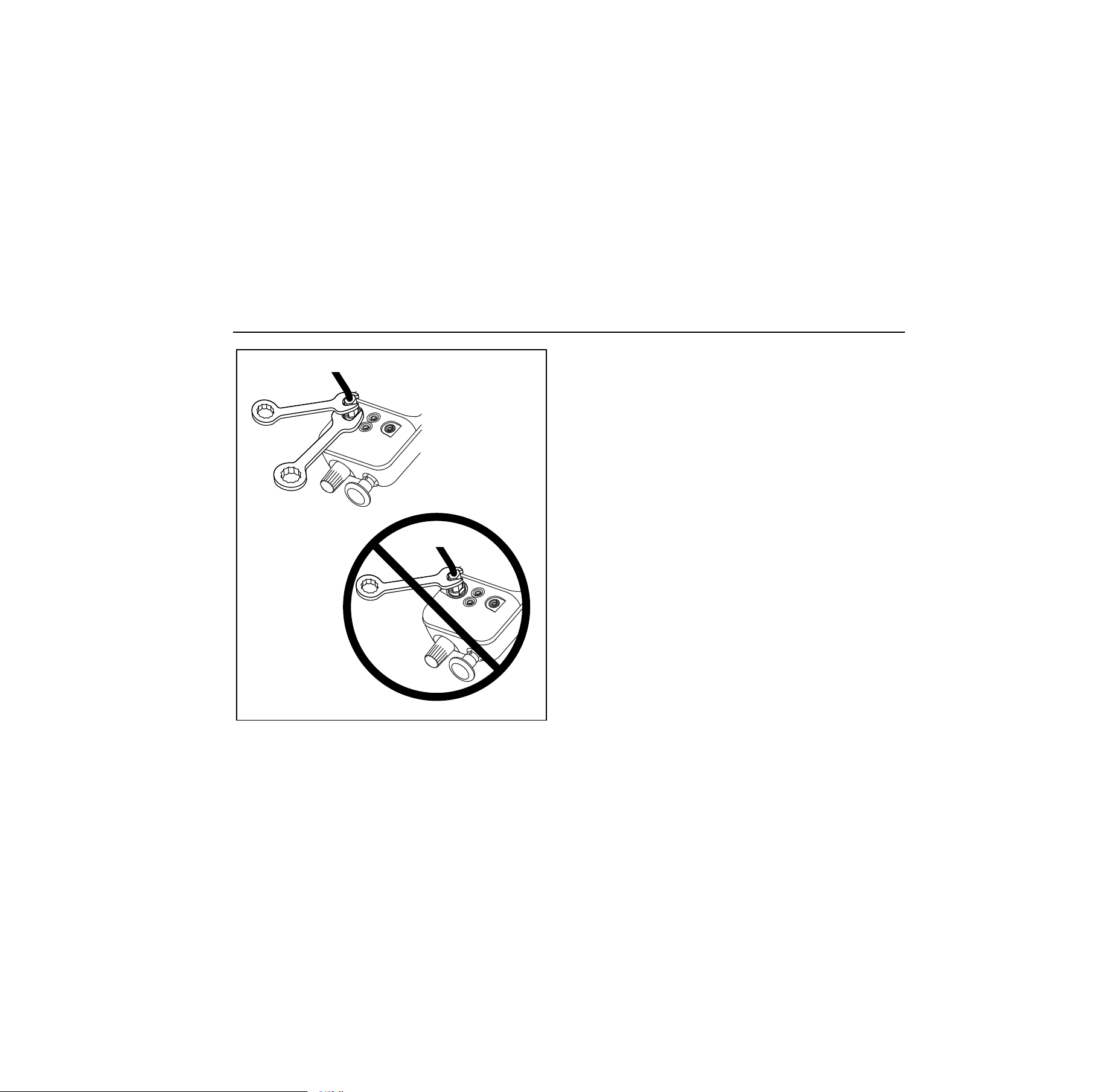
W Caution
To avoid mechanically damaging the Calibrator:
• Do not apply torque between the pressure fitting and the Calibrator case. See Figure 1 for the proper
use of tools.
• To avoid damage to the pump, use with dry air and non-corrosive gases only.
1.888.610.7664 sales@GlobalTestSupply.com
Fluke-Direct
.com
Pressure Calibrator
Safety Information
7
Hold in
fixed
position
wh001f.eps
Figure 1. Connection Technique
Faults and Damage
Applying a voltage greater than 30 V to the input of the
Calibrator invalidates its Ex Approval and may impair its
safe operation in an Ex-hazardous area.
If there is any reason to suspect that the safe operation of
the Calibrator has been affected, it must be immediately
withdrawn from use, and precautionary measures must be
taken to prevent any further use of the Calibrator in an Ex-
hazardous area.
Fully observe all instructions, warnings, and cautions
contained in this manual. In case of doubt due to
translation and/or printing errors, refer to the original
English users manual.
1.888.610.7664 sales@GlobalTestSupply.com
Fluke-Direct
.com

718Ex 30G/100G/300G
Users Manual
8
The safety features and integrity of the unit may be
compromised by any of the following:
• External damage to the housing
• Internal damage to the Calibrator
• Exposure to excessive loads
• Incorrect storage of the unit
• Damage sustained in transit
• Correct certification is illegible
• Using the product with the red holster removed
• Functioning errors occur
• Permitted limitations are exceeded
• Functioning errors or obvious measurement
inaccuracies occur which prevent further
measurement by the Calibrator
• Opening the case
Safety Regulations
The use of the Calibrator meets the requirements of the
regulations providing that the user observes and applies
the requirements as stated in the regulations and that
improper and incorrect use of the unit is avoided.
• Use must be restricted to the specified application
parameters.
• Do not open the Calibrator.
• Do not remove or install the battery within the
Ex-hazardous area.
• Do not carry additional batteries within the
Ex-hazardous area.
• Use only type-tested batteries. The use of any other
batteries will invalidate the Ex-certification and present
a safety risk.
• Do not use the Calibrator in an Ex-hazardous area
unless it is completely and securely fitted in its
accompanying red holster.
• Only use the Calibrator in circuits with compatible
entity parameters.
1.888.610.7664 sales@GlobalTestSupply.com
Fluke-Direct
.com
Pressure Calibrator
Getting Acquainted with the Calibrator
9
Certification Information
E
( II 1 G EEx ia IIC T4
Permitted for Zone 0 Equipment Group II, gas group
IIC hazardous atmospheres, temperature class T4
F
Class I Div. 1 Groups A-D T4 Intrinsically
Safe AEx ia IIC T4
Permitted for Division 1 hazardous atmospheres, Gas
Groups A-D, temperature class T4
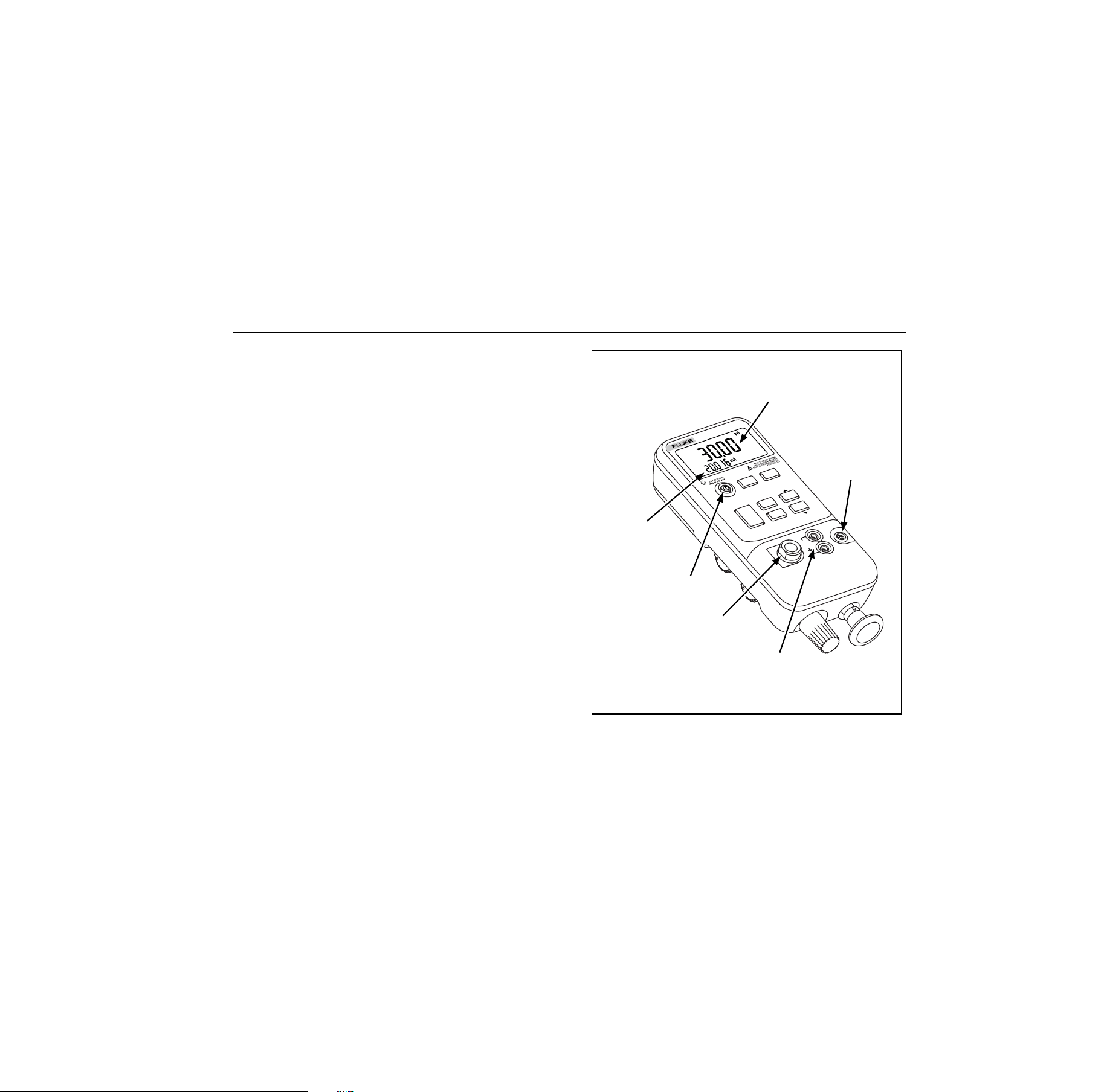
Getting Acquainted with the Calibrator
Press
O
to turn the Calibrator on and off. The Calibrator
displays pressure and current measurements
simultaneously. See Figure 2.
The upper part of the display shows the applied pressure
or vacuum. Vacuum is shown as a negative value. Press
U
to select a different unit. When cycling the power off
and on, the Calibrator retains the unit last used.
The lower part of the display shows the current (up to
24 mA) applied to the current (mA) inputs.
Pushbutton operation is described in Table 2. Pump
features are shown in Figure 3 and described in Table 3.
LR110460
AEx ia IIC T4
I.S. Class 1
Div 1 Group A-D
)
Current mA
measurement
Pressure
measurement
Pressure
module input
Pressure
sensor input
Current
input
On/Off Button
HO
LD
COM
mA
30V
24mA
MAX
RANGE
UNITS
ZERO
DAMP
MIN
MAX
CLR
SWITCH
TEST
HOLD
BAROM
ETRIC ADJ.
718Ex 100G
PRESSURE
CALIBRATOR
FLUKE 700PEx
ONLY
100psi 689kPa
200psi 1379kPa
MAX
alz005f.eps
Figure 2. Front Panel Features
1.888.610.7664 sales@GlobalTestSupply.com
Fluke-Direct
.com

718Ex 30G/100G/300G
Users Manual
10
Table 2. Pushbutton Functions
Pushbutton Description
U
Press to select a different pressure unit. All units are available when the pressure sensor input is used. For
higher pressure module inputs, inappropriate (out-of-range) units are not available.
D
Turns pressure reading damping on and off. With damping on, the Calibrator averages several
measurements before displaying a reading.
Z
Press to zero the pressure display. Vent pressure to atmosphere before pressing this pushbutton. For an
Absolute Pressure Module, see Zeroing with Absolute Pressure Modules.
N
Press to read the minimum pressure and current readings since power was turned on or
c
was pressed.
Press again to read the maximum pressure and current readings since power was turned on or
c
was
pressed.
S Use for pressure switch test. See Switch Test.
c
Press to clear the MIN, MAX, and switch test memories
h
Press
h
to freeze the display. The
g
symbol appears on the display. Press
h
again to resume
normal operation.
1.888.610.7664 sales@GlobalTestSupply.com
Fluke-Direct
.com

Pressure Calibrator
Zeroing with Absolute Pressure Modules
11
Power Saver
The Calibrator automatically turns off after 30 minutes of
inactivity. To reduce this time or disable this feature:
1. With the Calibrator OFF, press O.
P.S. xx is displayed, where xx is the turn-off time in
minutes. OFF means the power saver is disabled.
2. Press
h to decrease or c to increase the turn-off
time.
3. To disable, press
h until the display shows OFF.
The Calibrator resumes normal operation after 2 seconds.
Zeroing with Absolute Pressure Modules
For zeroing, adjust the Calibrator to read a known
pressure. This can be barometric pressure, if it is
accurately known. An accurate pressure standard can also
apply a pressure within range for any Absolute Pressure
Module. Adjust the Calibrator reading as follows:
1. Press and hold
Z.
2. Press
h to increase or h to decrease the
Calibrator reading to equal the applied pressure.
3. Release
Z to exit the zeroing procedure.
Press the
U button to convert to any convenient
measurement display unit.
1.888.610.7664 sales@GlobalTestSupply.com
Fluke-Direct
.com
718Ex 30G/100G/300G
Users Manual
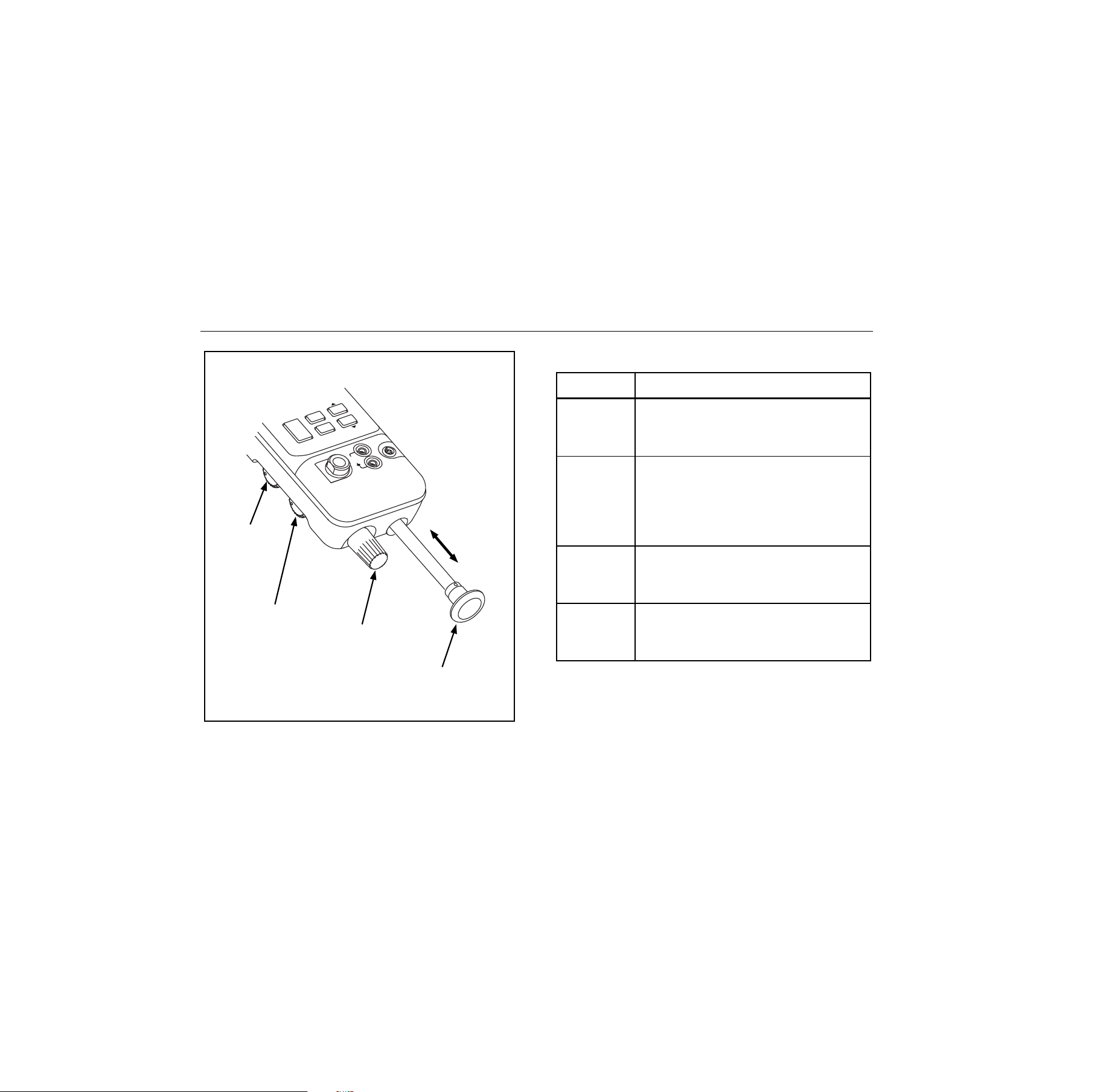
12
Pressure/
Vacuum
Switch
Fine
Adjustment
Knob
Internal Pump
Pressure/Vacuum
Release
Control
C
O
M
m
A
30V
2
4
m
A
M
A
X
R
A
N
G
E
Z
E
R
O
C
LR
H
O
LD
B
A
R
O
M
E
T
R
IC
A
D
J
.
M
IN
M
A
X
SWITCH
TEST
FLU
KE
700P
E
x
O
N
LY
10
0psi 689kP
a
20
0psi 1
379kP
a
M
A
X
alz009f.eps
Figure 3. Pump Features
Table 3. Pump Features
Item Description
Pressure
Vacuum
Switch
Rotate forward (clockwise) for pressure,
backward (counter-clockwise) for
vacuum.
Pressure
Vacuum
Release
Control
Rotate fully backward (counter-
clockwise) to release all pressure or
vacuum. (Rotate slightly for partial
release.) Rotate fully forward (clockwise)
to close valve.
Fine
Adjustment
Knob
Rotate either direction for precise
adjustment of applied pressure or
vacuum. Full rotation is about 30 turns.
Internal
Pump
Increase pressure on the inward stroke.
In vacuum mode, decrease pressure on
the outward stroke.
1.888.610.7664 sales@GlobalTestSupply.com
Fluke-Direct
.com

Pressure Calibrator
Calibrating a P/I Transmitter
13
Calibrating a P/I Transmitter
To calibrate a P/I (pressure to current) transmitter, apply a
pressure to the transmitter and measure the transmitter’s
current loop output. Pressure can be applied with the
Calibrator’s internal pump or with an external pump.
XW Warning
To avoid a violent release of pressure or vacuum,
always depressurize the system slowly using the
pressure/vacuum release control before detaching
any pressure line.
When measuring the pressure of potentially
hazardous gases, care must be taken to
minimize the possibility of leakage:
• Confirm that all pressure connections are
properly sealed.
• Confirm that the Pressure/Vacuum
Release Control is in the closed position
(fully clockwise) and the
Pressure/Vacuum switch is in the +
position (fully clockwise).
• If the Calibrator has been dropped or
subjected to rough handling, remove the
Calibrator to a safe area and check for
leaks to confirm the integrity of the
internal pneumatic components.
Using the Internal Pump
The internal pump can provide 30 psi (2.0685 bar) for
Model 718Ex 30G, 100 psi (6.895 bar) for Model 718Ex
100G, or 300 psi (20.68 bar) for Model 718Ex 300G.
The preferred use for the internal pump is shown in Figure
4, where the Calibrator displays pressure measured with
the internal sensor and provided by the internal pump.
The internal pump can also be used with certain Fluke
700PEx Series Pressure Modules. In this case, pressure
measured by the pressure module is displayed by the
Calibrator. Appropriate pressure modules for each
Calibrator model are identified in Table 4. Figure 5 shows
the internal pump being used with a pressure module.
XW Warning
If both a pressure module and the internal
sensor are connected, the Calibrator displays
ONLY the pressure module measurement.
1.888.610.7664 sales@GlobalTestSupply.com
Fluke-Direct
.com

718Ex 30G/100G/300G
Users Manual
14
To use the Calibrator’s internal pump, refer to Figure 3 and
perform the following steps:
1. Depressurize the line before connecting the
Calibrator.
2. Connect the pressure transmitter under test to the
Calibrator internal sensor as shown in Figure 4 (for
internal pressure sensor measurements) or Figure 5
(for pressure module measurements.)
Note
To avoid leaks, use Teflon tape or similar sealant
on all pressure connections.
3. Make sure the pressure/vacuum switch on the
Calibrator is in the desired position. Forward
(clockwise) is for pressure; backward (counter-
clockwise) is for vacuum.
4. Turn the pressure/vacuum release control backward
(counter-clockwise) to vent pressure/vacuum from the
pump.
5. Press Zto zero the pressure display.
6. Turn the fine adjustment knob to mid-range.
7. Turn the pressure/vacuum release control forward
(clockwise) to close the release valve.
8. Work the pump handle in and out to apply
incrementally larger pressure/vacuum changes.
Shorten the stroke to apply smaller increments of
pressure/vacuum change.
9. To make very small pressure/vacuum changes, use
the fine adjustment knob.
Note
This knob adjusts a small internal reservoir to
vary the total volume. With larger external
pressure/vacuum volumes, this control will adjust
pressure or vacuum within a smaller range.
10. Depressurize the system before disconnecting the
pressure line.
1.888.610.7664 sales@GlobalTestSupply.com
Fluke-Direct
.com
Pressure Calibrator
Calibrating a P/I Transmitter
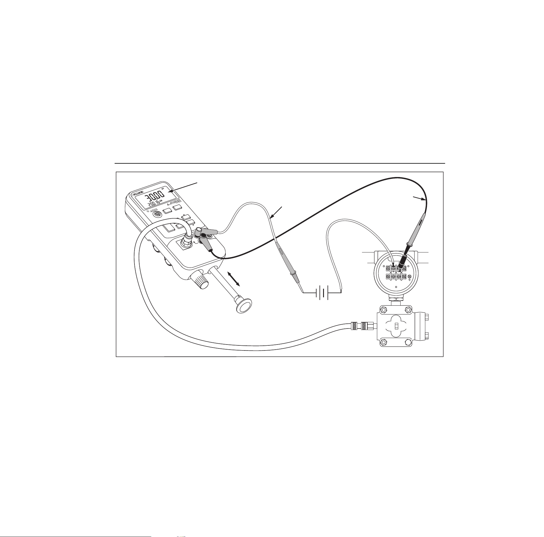
15
FLUKE 700PEx
ONLY
mA
30V
MAX
100psi 689kPa
RANGE
200psi 1379kPa
MAX
LR110460
AEx ia IIC T4
I.S. Class 1
Div 1 Group A-D
)
SIGN AL
TEST
+
–
HOLD
UNITS
ZERO
DAMP
MIN
MAX
CLR
MAX
HOLD
BAROMETRIC ADJ.
718Ex 100G
PRESSURE
CALIBRATOR
Red
Black
Internal Pressure Sensor Reading
External
Loop Supply
alz002f.eps
Figure 4. Internal Pressure Sensor with Internal Pump
1.888.610.7664 sales@GlobalTestSupply.com
Fluke-Direct
.com
718Ex 30G/100G/300G
Users Manual
16
SIGN AL
TEST
+
–
FLUKE 700PEx
O
N
LY
mA
30
V
MAX
100psi 68
9kPa
RANGE
200psi 1379kPa
MAX
LR110460
AEx ia IIC T4
I.S. Class 1
Div 1 Gro
u
p A-D
)
HOLD
U
N
ITS
ZERO
DAMP
MIN
MAX
CLR
MAX
HOLD
BAROMETRIC ADJ.
718Ex 100G
PRESSURE
CALIBRATOR
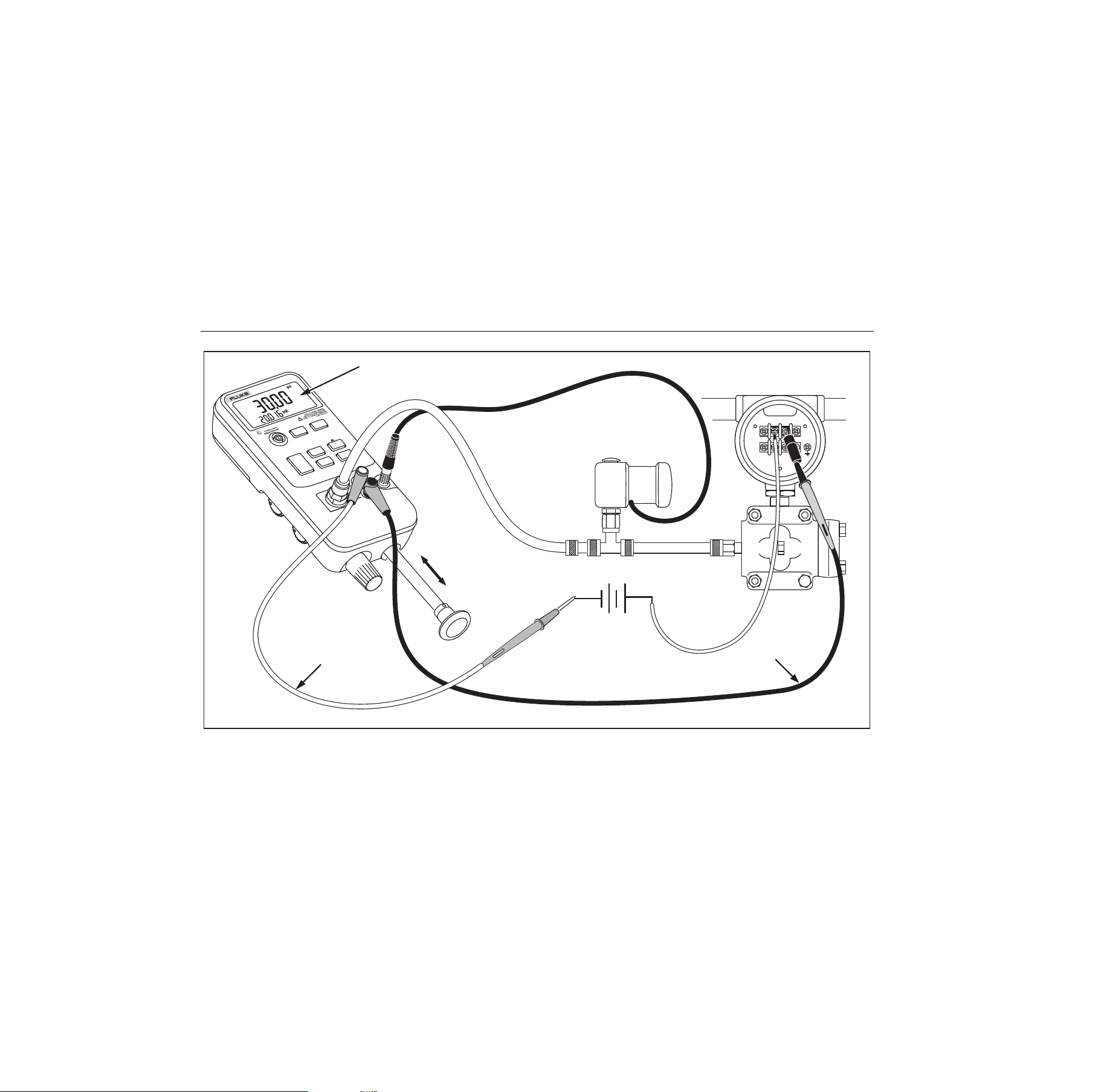
Pressure Module
Black
Pressure Module Reading
Red
External
Loop Supply
alz010f.eps
Figure 5. Pressure Module with Internal Pump
1.888.610.7664 sales@GlobalTestSupply.com
Fluke-Direct
.com

Pressure Calibrator
Calibrating a P/I Transmitter
17
Table 4. Recommended Pressure Modules
External
Pump
Internal Pump
Pressure
Module
718Ex
30G/100G/
300G
718Ex
30G
718Ex
100G
718Ex
300G
700P01Ex X X X X
700P24Ex X X X X
700P05Ex X X X X
700P06Ex X X X
700P27Ex X X
700P09Ex X
700PA4Ex X X X X
700P29Ex X
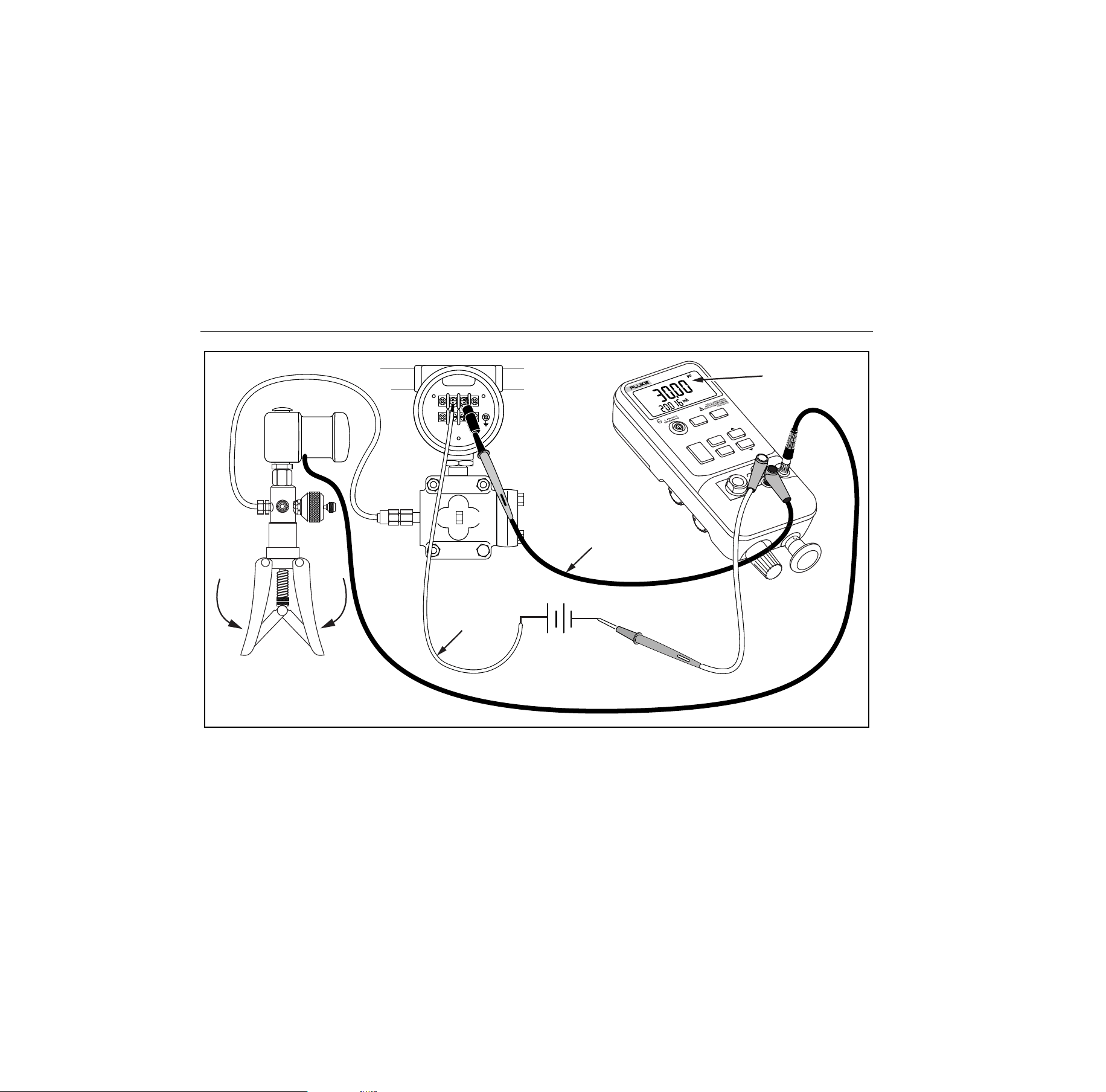
Using an External Pump
XW Warning
To avoid damage to the Calibrator and possible
release of pressure, do not connect the internal
sensor to an external pressure source that
exceeds 30 psi for Model 718Ex 30G, 100 psi for
Model 718Ex 100G, or 300 psi for Model 718Ex
300G.
To develop higher pressure or vacuum, use an external
pump. Use a Fluke 700PEx Pressure Module connected to
the pressure module input on the Calibrator. Pressure
modules are listed in Table 4. Make overall connections as
shown in Figure 6.
Refer to setup and operating instructions included with the
pressure module and pump.
1.888.610.7664 sales@GlobalTestSupply.com
Fluke-Direct
.com
718Ex 30G/100G/300G
Users Manual
18
FLUKE 700PEx
ONLY
mA
3
0
V
M
A
X
100psi 689kPa
R
A
N
G
E
200psi 1379kPa
MAX
SIGNAL
TEST
+
–
Pressure Module
Red
Black
H
OLD
Pressure
Module Reading
UNITS
Z
E
R
O
DAMP
CLR
HOLD
B
ARO
M
ETR
IC
AD
J.
718Ex 100G
PRESSURE
CALIBRATOR
MIN
MAX
SWITCH
TEST
1
LR
11
046
0
A
E
x ia IIC
T
4
I.S
. C
lass 1
D
iv 1 G
roup
A
-D
)
External
Loop Supply
alz006f.eps
Figure 6. Pressure Module with External Pump
1.888.610.7664 sales@GlobalTestSupply.com
Fluke-Direct
.com
Pressure Calibrator
External Fluke Pressure Module Compatibility
19
External Fluke Pressure Module
Compatibility
If inappropriate units are selected, the output of Fluke
700PEx pressure modules can cause the Calibrator
display to overflow (OL), or display values that are too low
to be read. Refer to Table 5 for appropriate unit and range
compatibility.
Table 5. Fluke Pressure Module Compatibility
Pressure Unit Module Compatibility
psi Available on all pressure ranges
inH
2
0 All ranges through 3000 psi
cmH
2
0 All ranges through 1000 psi
bar 15 psi and above
mbar All ranges through 1000 psi
kPa Available on all pressure ranges
inHg Available on all pressure ranges
mmHg All ranges through 1000 psi
kg/cm
2
15 psi and above
1.888.610.7664 sales@GlobalTestSupply.com
Fluke-Direct
.com

718Ex 30G/100G/300G
Users Manual
20
Cleaning the Pump Valve Assembly
1. Using a small screwdriver, remove the two valve
retention caps located in the oval-shaped opening on
the back side of the Calibrator.
2. Gently remove the spring and o-ring assembly.
3. Set aside the valve assemblies in a safe area and
clean out the valve body using a cotton swab soaked
in IPA (isopropyl alcohol).
4. Repeat this process several times using a new cotton
swab each time until there is no remaining residue.
5. Pump the unit several times and check again for
residue.
6. Clean the o-ring assembly and the o-ring on the
retention caps with IPA and inspect the o-rings closely
for any cuts, nicks, or wear. Replace if needed.
7. Inspect the springs for wear or loss of tension. They
should be approximately 8.6 mm long in the relaxed
state. If they are shorter than that, they may not allow
the o-ring to seat properly. Replace if needed.
8. Once all parts have been cleaned and inspected,
reinstall the o-ring and spring assemblies into the
valve body.
9. Reinstall the retention caps and gently tighten the
cap.
10. Seal the output of the Calibrator and pump up the unit
to at least 50 % its rated pressure.
11. Release the pressure and repeat several times to
ensure that the o-rings seat properly.
The Calibrator is now ready to use.
Switch Test
To perform a switch test, follow these steps:
Note
This example used a normally closed switch. The
procedure is the same for an open switch but the
display reads OPEN instead of CLOSE.
1. Connect the Calibrator mA and COM terminals to the
switch using the pressure switch terminals and
connect the pump from the Calibrator to the pressure
switch. The polarity of the terminals does not matter.
2. Make sure the vent on the pump is open and zero the
Calibrator if necessary. Close the vent after zeroing
the Calibrator.
1.888.610.7664 sales@GlobalTestSupply.com
Fluke-Direct
.com

Pressure Calibrator
Maintenance
21
3. Press
S
to enter pressure switch test mode. The
Calibrator will display CLOSE instead of a mA
measurement.
4. Apply pressure with the pump slowly until the switch
opens.
Note
In the switch test mode, the display update rate is
increased to help capture changing pressure
inputs. Even with this enhanced sample rate,
pressuring the device under test should be done
slowly to ensure accurate readings.
5. OPEN is displayed once the switch is open. Bleed the
pump slowly until the pressure switch closes. RCL
appears on the display.
6. Press
S to read the pressure values for when the
switch opened, for when it closed, and for the
deadband.
7. Hold
Sfor three seconds to exit the switch test or
press
c to reset the switch test.
Maintenance
XW Warning
To avoid possible electric shock, personal
injury, or sudden release of pressure, review
Safety Information before proceeding.
For maintenance procedures not described in this manual,
or if the Calibrator needs repair, contact a Fluke Service
Center. See Contacting Fluke.
In Case of Difficulty
• After removing the Calibrator from the Ex-hazardous
area, check the battery, test leads, pressure module,
and pressure tubing. Follow replacement and
connection instructions properly.
• Review this manual and control drawing to make sure
the Calibrator is used correctly.
If the Calibrator needs repair, and the Calibrator is under
warranty, see the warranty statement for terms. If the
warranty has lapsed, the Calibrator can be repaired and
returned for a fixed fee.
1.888.610.7664 sales@GlobalTestSupply.com
Fluke-Direct
.com
718Ex 30G/100G/300G
Users Manual
22
Cleaning
Periodically wipe the case with a damp cloth; do not use
abrasives or solvents.
Calibration
Fluke recommends that the Calibrator be calibrated once
yearly to ensure that it performs according to its
specifications. A calibration manual is available.
Call 1-800-526-4731 from the U.S.A. and Canada. In other
countries, contact a Fluke Service Center.
Replacing the Battery
XW Warning
• To avoid false readings, which could lead to
possible electric shock or personal injury,
replace the battery as soon as the battery
indicator
B
appears.
• Remove the Calibrator from the Ex-hazardous
area before opening the battery door.
• Use only the battery types listed in the
Approved Battery Table.
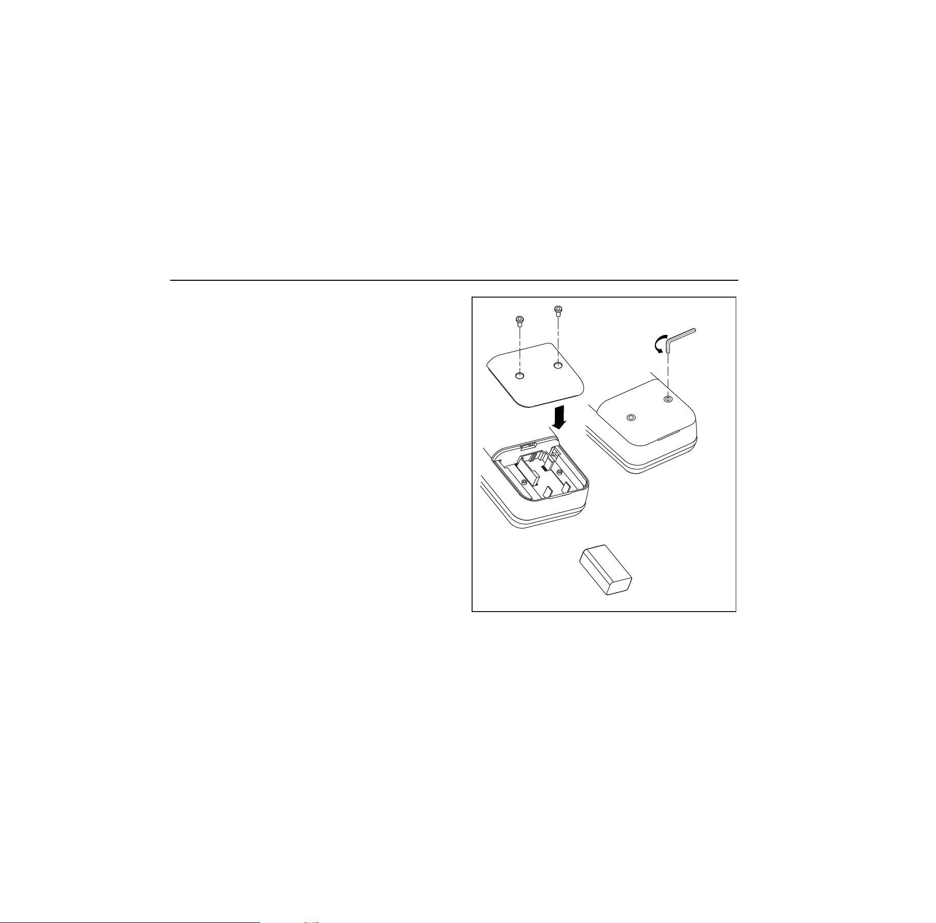
When
B
appears on the display, replace the 9 V
alkaline battery. Refer to Figure 7.
Hex Head
Wrench
alz008f.eps
Figure 7. Battery Replacement
1.888.610.7664 sales@GlobalTestSupply.com
Fluke-Direct
.com

Pressure Calibrator
Maintenance
23
Approved Batteries
Battery Manufacturer Type
Alkaline, 9 volt Duracell 6LR61/MN1604
Alkaline Ultra, 9 volt Duracell 6LR61/MX1604
Alkaline Energizer, 9 volt Eveready 6LR61/522
Alkaline Power Line Industrial Battery, 9 volt Panasonic 6LR61.9V
1.888.610.7664 sales@GlobalTestSupply.com
Fluke-Direct
.com
718Ex 30G/100G/300G
Users Manual
24
Parts and Accessories
Refer to Table 6 for a list of replacement parts and accessories.
Table 6. Replacement Parts and Accessories
Model No. Description Part Qty
AC72 Alligator clips (Black) 1670652 1
AC72 Alligator clips (Red) 1670641 1
BT1 9 V battery, ANSI/NEDA 1604A or IEC 6LR61 822270 or see Battery Table 1
Holster Holster, Red 2096118 1
- Battery Door Assembly 2117013 1
- Test lead set 855742 1
- 718Ex CD-ROM (contains Users Manual) 2097427 1
- 71X Series Calibration Manual 686540 Opt
- 718Ex Control Drawing 2117024 1
1.888.610.7664 sales@GlobalTestSupply.com
Fluke-Direct
.com
Pressure Calibrator
Specifications
25
Specifications
Specifications are based on a one year calibration cycle
and apply for ambient temperature from +18 °C to +28 °C
unless stated otherwise. Counts are the number of
increments or decrements of the least significant digit.
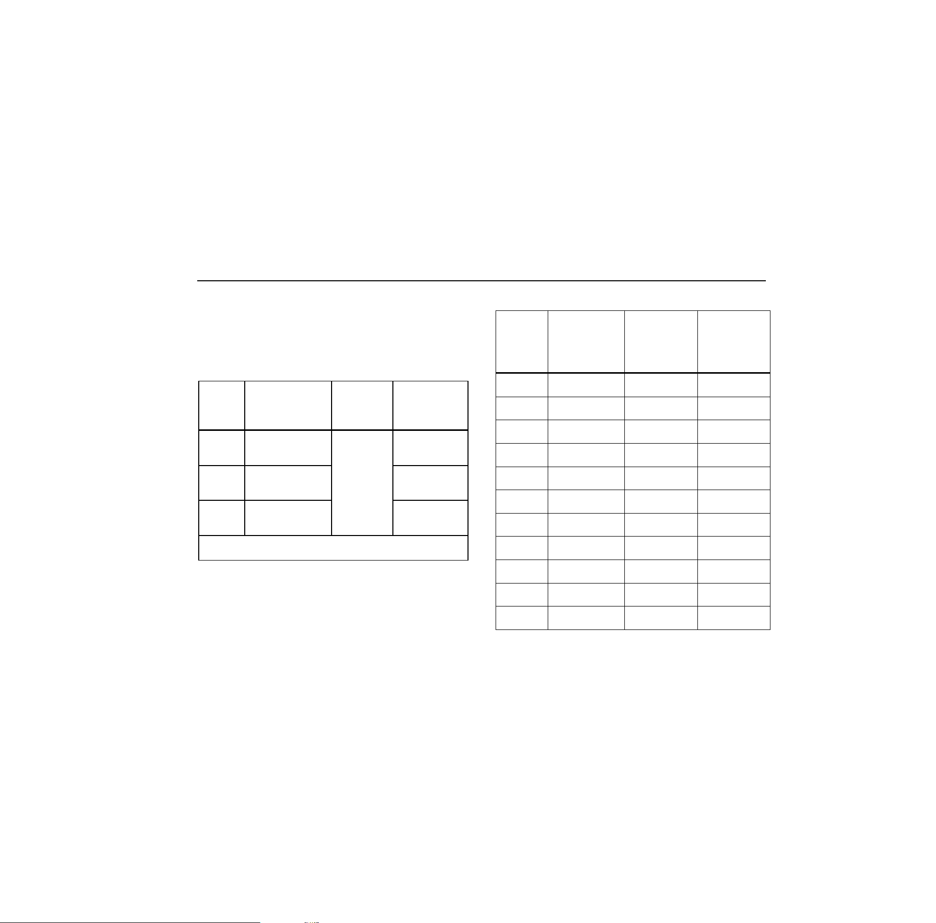
Pressure Sensor Input
Model Range Accuracy
Max Non-
destructive
Pressure
30G
-12 to 30 psi
(-83 to 207 kPa)
60 psi
(413 kPa)
100G
-12 to 100 psi
(-83 to 690 kPa)
200 psi
(1.4 mPa)
300G
-12 to 300 psi
(-83 to 2068 kPa)
±0.05 %
of range
375 psi
(2.6 mPa)
Temperature coefficient: 0.01 % of range per
°
C for temperature
ranges -10
°
C to 18
°
C and 28
°
C to 55
°
C
Pressure Sensor Range and Resolution
Displayed
Pressure
Units
Model 718Ex
30G Range and
Resolution
Model 718Ex
100G Range
and
Resolution
Model 718Ex
300G Range
and
Resolution
psi
-12.000 to
30.000 psi
-12.00 to
100.00 psi
-12.00 to
300.00 psi
inH
2
O at
4 °C
-332.16 to
830.40 inH
2
O
-332.2 to
2768.0 inH
2
O
-332.2 to
8304 inH
2
O
inH
2
O at
20 °C
-332.75 to
831.87 inH
2
O
-332.8 to
2772.9 inH
2
O
-332.8 to
8318.7 inH
2
O
cmH
2
O at
4 °C
-843.6 to
2109.0 cmH
2
O
-843.6 to
7030.0 cmH
2
O
-843.6 to
21090 cmH
2
O
cmH
2
O at
20 °C
-845.2 to
2113.0 cmH
2
O
-845.2 to
7043.0 cmH
2
O
-845.2 to
21129 cmH
2
O
bar
-0.8274 to
2.0685 bar
-0.8274 to
6.8950 bar
-0.8274 to
20.685 bar
mbar
-827.4 to
2068.5 mbar
-827.4 to
6895.0 mbar
-827.4 to
20685 mbar
kPa
-82.74 to
206.85 kPa
-82.74 to
689.50 kPa
-82.74 to
2068.5 kPa
inHg
-24.432 to
61.080 inHg
-24.43 to
203.60 inHg
-24.43 to
610.8 inHg
mmHg
-620.6 to
1551.4 mmHg
-620.6 to
5171.5 mmHg
-620.6 to
15514.5 mmHg
kg/cm
2
-0.8437 to
2.1090 kg/cm
2
-0.8437 to
7.0306 kg/cm
2
-0.8437 to
21.0918 kg/cm
2
1.888.610.7664 sales@GlobalTestSupply.com
Fluke-Direct
.com

718Ex 30G/100G/300G
Users Manual
26
Pressure Module Input
Range Resolution Accuracy
(determined by Pressure Module)
DC mA Input
Range Resolution
Accuracy, ±(% of
Reading + Counts)
24 mA 0.001 mA 0.02 + 2
Temperature coefficient: 0.005 % of range per
°
C for
temperature ranges -10
°
C to 18
°
C and 28
°
C to 55
°
C
General Specifications
Maximum voltage applied between either mA terminal and earth ground or between the mA terminals: 30 V
Pressure sensor media: Non-corrosive gasses only
Storage temperature: -40 °C to 71 °C
Operating temperature: -10 °C to 55 °C
Relative humidity: 95 % up to 30 °C, 75 % up to 40 °C, 45 % up to 50 °C, and 35 % up to 55 °C
EMC: Complies with EN61326, Criteria C
Pollution Degree 2
1.888.610.7664 sales@GlobalTestSupply.com
Fluke-Direct
.com
Pressure Calibrator
Specifications
27
Product Compliance Markings
E
( II 1 G EEx ia IIC T4
Kema 04ATEX1061 X
F
Class I Div. 1 Groups A-D T4
AEx ia IIC T4
Ta = -10 °C +55 °C
; Conforms to relevant Australian standards.
Manufactured by Martel Electronics Inc., 1F Commons Drive, Londonderry, NH USA
Additional Safety Information: Complies with CAN/CSA C22.2 No. 1010.2:1995. Complies with ANSI/ISA S82.01-1995.
Complies with IEC 61010-1-95 CAT I, 30 V
Entity Parameters:
Vi, Ui Ii Pi Ci Li
30 V 250 mA 1.88 W 0 μF 0 mH
Co Lo
Vo, Uo Io Po
IIC IIB IIA IIC IIB IIA
7.14 V 1.09 mA 1.9 mW 13.5 μF 240 μF 1000 μF 1.0 H 3.0 H 8.0 H
Power requirements: See Approved Batteries.
Size: 66 mm H x 94 mm W x 216 mm L (2.60 in H x 3.70 in W x 8.5 in L)
Weight: 992 g (35 oz)
1.888.610.7664 sales@GlobalTestSupply.com
Fluke-Direct
.com