
January 2014
© 2014 Fluke Corporation. All rights reserved. Specifications are subject to change without notice.
All product names are trademarks of their respective companies.
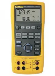
714B
Thermocouple Calibrator
Users Manual
1.888.610.7664 sales@GlobalTestSupply.com
Fluke-Direct
.com

LIMITED WARRANTY AND LIMITATION OF LIABILITY
This Fluke product will be free from defects in material and workmanship for three years from the date of purchase. This
warranty does not cover fuses, disposable batteries, or damage from accident, neglect, misuse, alteration, contamination, or
abnormal conditions of operation or handling. Resellers are not authorized to extend any other warranty on Fluke’s behalf.
To obtain service during the warranty period, contact your nearest Fluke authorized service center to obtain return
authorization information, then send the product to that Service Center with a description of the problem.
THIS WARRANTY IS YOUR ONLY REMEDY. NO OTHER WARRANTIES, SUCH AS FITNESS FOR A PARTICULAR
PURPOSE, ARE EXPRESSED OR IMPLIED. FLUKE IS NOT LIABLE FOR ANY SPECIAL, INDIRECT, INCIDENTAL OR
CONSEQUENTIAL DAMAGES OR LOSSES, ARISING FROM ANY CAUSE OR THEORY. Since some states or countries
do not allow the exclusion or limitation of an implied warranty or of incidental or consequential damages, this limitation of
liability may not apply to you.
11/99
1.888.610.7664 sales@GlobalTestSupply.com
Fluke-Direct
.com

i
Table of Contents
Title Page
Introduction .................................................................................................................... 1
How to Contact Fluke ..................................................................................................... 1
Safety Information .......................................................................................................... 3
Safe Working Practices .................................................................................................. 3
Standard Equipment....................................................................................................... 5
Input and Output Terminals ............................................................................................ 7
Keys ............................................................................................................................... 9
Display ........................................................................................................................... 11
Auto Power-Off ............................................................................................................... 13
Auto Backlight-Off .......................................................................................................... 13
Display Contrast Adjustment .......................................................................................... 13
Magnet Mounting and Hanging Strap ............................................................................. 14
Measure mA Current ...................................................................................................... 15
Measure Temperature .................................................................................................... 15
Use Thermocouples .................................................................................................. 15
Set Temperature Unit ................................................................................................ 15
Simulate Thermocouples ................................................................................................ 19
Scale mA Channel to Temperature ................................................................................ 21
Set 0 % and 100 % Output Parameters ......................................................................... 21
1.888.610.7664 sales@GlobalTestSupply.com
Fluke-Direct
.com

714B
Users Manual
ii
Step and Ramp Modes .................................................................................................. 22
Auto Storage of Settings ................................................................................................ 22
Replace the Batteries .................................................................................................... 23
Maintenance .................................................................................................................. 24
Clean the Product ..................................................................................................... 24
Service Center Calibration or Repair ........................................................................ 24
Replacement Parts ................................................................................................... 25
Specifications ................................................................................................................ 27
Thermocouple mV Input ............................................................................................ 27
Thermocouple mV Output ......................................................................................... 27
Thermocouple mA Input ............................................................................................ 27
Thermocouple Input and Output ............................................................................... 28
General Specifications ................................................................................................... 31
1.888.610.7664 sales@GlobalTestSupply.com
Fluke-Direct
.com

iii
List of Tables
Table Title Page
1. Summary of Source and Measure Functions ........................................................................ 2
2. International Symbols ............................................................................................................ 4
3. Input/Output Terminals and Connectors ................................................................................ 8
4. Key Functions ........................................................................................................................ 10
5. Elements on the Display ........................................................................................................ 12
6. Thermocouple Types Accepted ............................................................................................. 16
7. Replacement Parts ................................................................................................................ 25
1.888.610.7664 sales@GlobalTestSupply.com
Fluke-Direct
.com

v
List of Figures
Figure Title Page
1. Standard Equipment .............................................................................................................. 6
2. Input/Output Terminals and Connectors ................................................................................ 7
3. Keys ...................................................................................................................................... 9
4. Elements of a Typical Display ............................................................................................... 11
5. Magnet Mounting with Hanging Strap ................................................................................... 14
6. Measure Temperature with a Thermocouple ......................................................................... 18
7. Connections for Simulating a Thermocouple ......................................................................... 20
8. Replace the Batteries ............................................................................................................ 23
9. Replacement Parts ................................................................................................................ 26
1.888.610.7664 sales@GlobalTestSupply.com
Fluke-Direct
.com

714B
Users Manual
2
Table 1. Summary of Source and Measure Functions
Function Measure Source
Thermocouple and mV Types E, J, K, T, B, R, S, L, U, N, C, BP, XK, G, D, P, M and mV
Other functions Step, Ramp
1.888.610.7664 sales@GlobalTestSupply.com
Fluke-Direct
.com

Thermocouple Calibrator
Safety Information
3
Safety Information
A Warning identifies conditions and procedures that are
dangerous to the user. A Caution identifies conditions and
procedures that can cause damage to the Product or the
equipment under test.
International electrical symbols used on the Product and in
this manual are explained in Table 2.
Safe Working Practices
Review the safety information and comply with the safe
working practices.
Warning
To prevent possible electrical shock, fire, or
personal injury:
• Carefully read all instructions.
• Read all safety Information before you
use the Product.
• Use the Product only as specified, or the
protection supplied by the Product can
be compromised.
• Do not use the Product around explosive
gas, vapor, or in damp or wet
environments.
• Never apply more than 30 V between any
two terminals, or between any terminal
and earth ground.
• Do not connect any test leads to voltages
above 30 V when used with the product,
even if ratings above 30 V appear on the
test leads.
• Do not use and disable the Product if it is
damaged.
• The battery door must be closed and
locked before you operate the Product.
• Remove all probes, test leads, and
accessories before the battery door is
opened.
• Remove the input signals before you
clean the Product.
• Have an approved technician repair the
Product.
• Replace the batteries when the low
battery indicator shows to prevent
incorrect measurements.
For safe operation and maintenance of the
Product:
• Repair the Product before use if the
battery leaks.
• Remove the batteries if the Product is not
used for an extended period of time, or if
stored in temperatures above 50 °C. If the
batteries are not removed, battery
leakage can damage the Product.
1.888.610.7664 sales@GlobalTestSupply.com
Fluke-Direct
.com

714B
Users Manual
4
Table 2. International Electrical Symbols
Earth Ground Battery
Conforms to relevant Australian
Standards.
Risk of danger. Important information. See Manual.
Inspected and licensed by TÜV Product
Services.
Conforms to European Union directives.
CAT II
MEASUREMENT CATEGORY II is
applicable to test and measuring circuits
connected directly to utilization points
(socket outlets and similar points) of the
low voltage MAINS installation.
CAT III
MEASUREMENT CATEGORY III is applicable to test and
measuring circuits connected to the distribution part of the
building’s low-voltage MAINS installation.
CAT IV
MEASUREMENT CATEGORY IV is
applicable to test and measuring circuits
connected at the source of the building’s
low voltage MAINS installation.
Conforms to relevant North American Safety Standards.
This product complies with the WEEE Directive (2002/96/EC) marking requirements. The affixed label indicates that you
must not discard this electrical/electronic product in domestic household waste. Product Category: With reference to the
equipment types in the WEEE Directive Annex I, this product is classed as category 9 "Monitoring and Control
Instrumentation" product. Do not dispose of this product as unsorted municipal waste. Go to Fluke’s website for recycling
information.
1.888.610.7664 sales@GlobalTestSupply.com
Fluke-Direct
.com

Thermocouple Calibrator
Standard Equipment
5
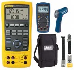
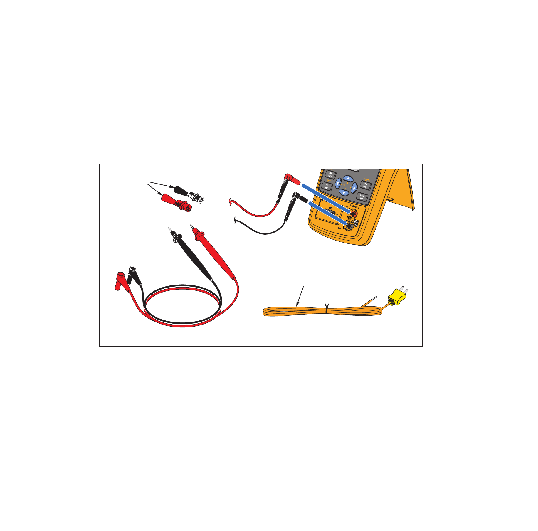
Standard Equipment
The items listed below and shown in Figure 1 are
included with your Product. If the Product is damaged or
something is missing, contact the place of purchase
immediately. To order replacement parts or spares, see
the user-replaceable parts list in Table 7.
• AC175 alligator clips (1 set)
• TL75 test leads (1 set)
• TC Cap for TC hole
• Mini standard TC plugs (with 80cm TC wire)
package (Including Type K)
• 4 AA alkaline batteries
• Magnet Strap TPAK
• 712B/714B Safety Sheet
• 714B Quick Reference Guide
• 714B Users Manual (available on Fluke’s website)
1.888.610.7664 sales@GlobalTestSupply.com
Fluke-Direct
.com
714B
Users Manual
6
TC Plugkit
K Type
AC175
Alligator Clips
TL75
Test Leads
hrk01.eps
Figure 1. Standard Equipment
1.888.610.7664 sales@GlobalTestSupply.com
Fluke-Direct
.com
Thermocouple Calibrator
Input and Output Terminals
7
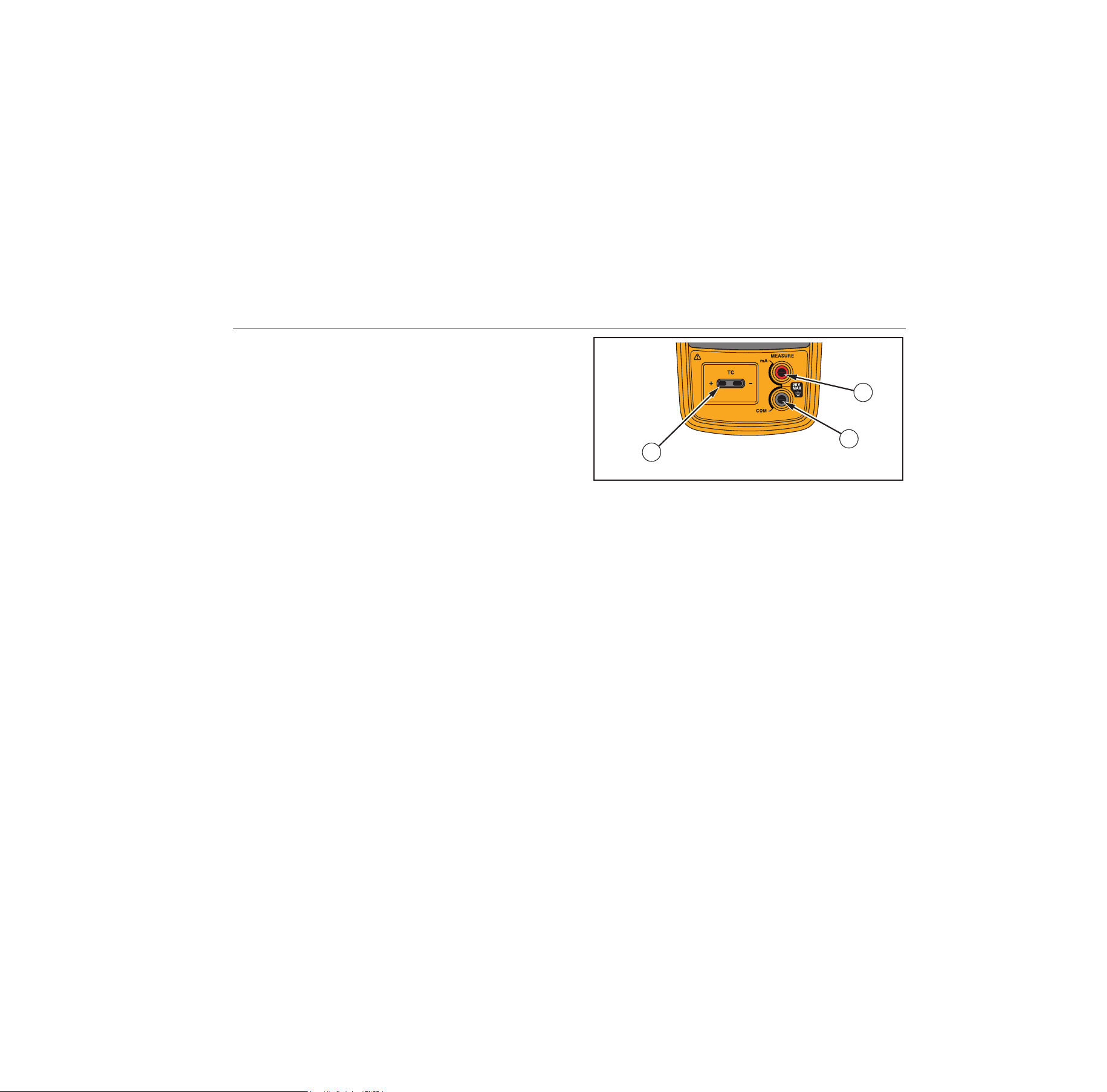
Input and Output Terminals
Figure 2 shows the input and output terminals on the
Product. Table 3 explains their use.
1
2
3
hrk02.eps
Figure 2. Input/Output Terminals and Connectors
1.888.610.7664 sales@GlobalTestSupply.com
Fluke-Direct
.com

714B
Users Manual
8
Table 3. Input/Output Terminals and Connectors
No. Name Description
,
MEASURE mA
terminals
Input terminals for measuring current.
TC input/output
Terminal for measuring or simulating thermocouples. This terminal accepts a
miniature polarized thermocouple plug with flat, in-line blades spaced 7.9 mm
(0.312 in) center to center.
1.888.610.7664 sales@GlobalTestSupply.com
Fluke-Direct
.com
Thermocouple Calibrator
Keys
9
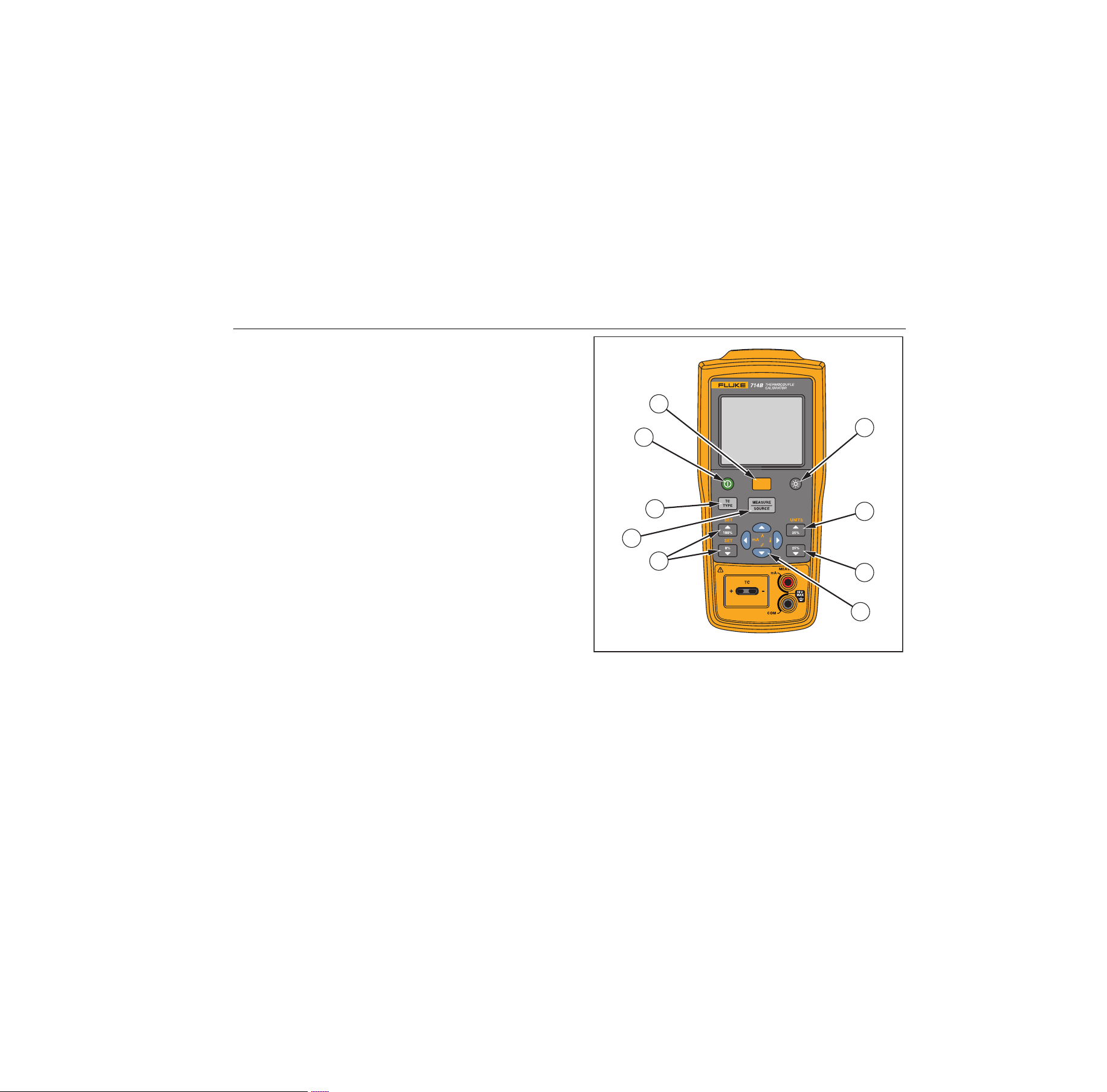
Keys
The Product has keys for different purposes. Some keys
have secondary functions that are available when SHIFT
already shows on the display.
Figure 3 shows the Product keys and Table 4 explains
their use.
1
8
9
2
3
6
3
4
5
7
hrk03.eps
Figure 3. Keys
1.888.610.7664 sales@GlobalTestSupply.com
Fluke-Direct
.com

714B
Users Manual
10
Table 4. Key Functions
No. Name Description
Turns the power on or off.
Shifts to secondary function when pushed before other keys (Shift mode).
Turns backlight on or off.
Increments output by 25 % of span. Secondary function: toggles between temperature units (°C or
°F.).
Decreases output by 25 % of span.
Up/down arrow increases or decreases the source level. Cycles through different options.
Secondary functions: Enters Ramp or Step mode.
Left/right arrow cycles through and highlights the field to be edited.
In contrast adjustment mode; left- lightens contrast, right- darkens contrast.
Secondary functions: Left arrow enters mA measurement; right arrow enters temperature
measurement.
Sets a source value to 100 % or 0 % of span.
Secondary function: enables automatic value span of 100 % or 0 %.
Shifts between Measure and Source modes.
Selects TC (thermocouple) measurement and sourcing function.
1.888.610.7664 sales@GlobalTestSupply.com
Fluke-Direct
.com
Thermocouple Calibrator
Display
11
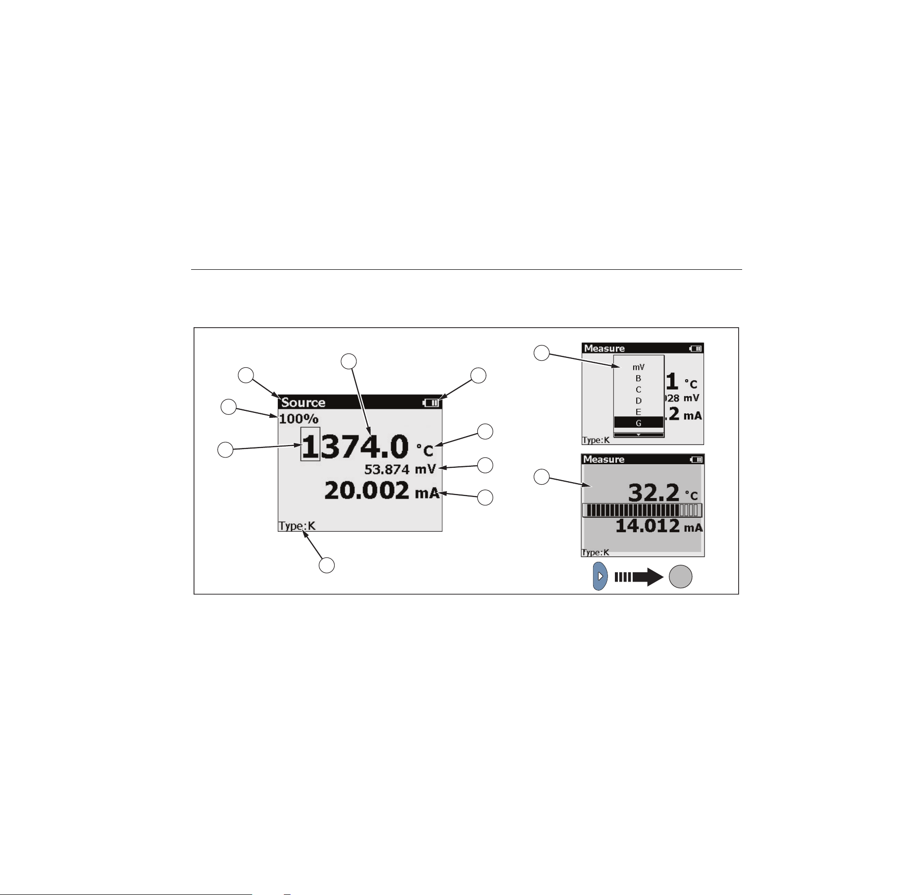
Display
Figure 4 shows the elements of a typical display. Figure 5
describes the elements.
8
9
1
2
3
4
5
6
7
10
11
hrk15.eps
Figure 4. Elements of a Typical Display
1.888.610.7664 sales@GlobalTestSupply.com
Fluke-Direct
.com

714B
Users Manual
12
Table 5. Elements on the Display
Item
No.
Description
100 % of value span
Source or Measure mode
Temperature reading
Battery usage status
Unit of temperature
mV reading
mA reading
Selected TC type
Selected digit that can be edited
TC type list
Display contrast bar
1.888.610.7664 sales@GlobalTestSupply.com
Fluke-Direct
.com

Thermocouple Calibrator
Auto Power-Off
13
Auto Power-Off
The Product provides an auto power-off function to save
power. When the auto power-off mode is enabled, the
Product automatically powers off after 15 minutes of
inactivity.
To enable the auto power-off mode:
1. Push .
2. When SHIFT shows on the display, push .
3. In the displayed setting list, highlight the Auto
poweroff option, and then use to select this option.
To disable the the auto power-off mode:
1. Push .
2. When SHIFT shows on the display, push .
3. In the displayed setting list, highlight the Auto
poweroff option, and then use to deselect this
option.
Auto Backlight-Off
The Product provides an auto backlight-off function to
save power. When the auto backlight-off mode is enabled,
the backlight automatically turns off after 2 minutes of
inactivity.
To enable the auto backlight-off mode:
1. Push .
2. When SHIFT shows on the display, push .
3. In the displayed setting list, highlight the Auto
backlight off option, and then use to select this
option.
To disable the the auto backlight-off mode:
1. Push .
2. When SHIFT shows on the display, push .
3. In the displayed setting list, highlight the Auto
backlight off option, and then use to deselect this
option.
Display Contrast Adjustment
The Product allows you to adjust the display contrast.
To adjust the display contrast:
1. Push until Measure shows on the display.
2. Push to darken contrast, or to lighten contrast.
1.888.610.7664 sales@GlobalTestSupply.com
Fluke-Direct
.com
714B
Users Manual
14
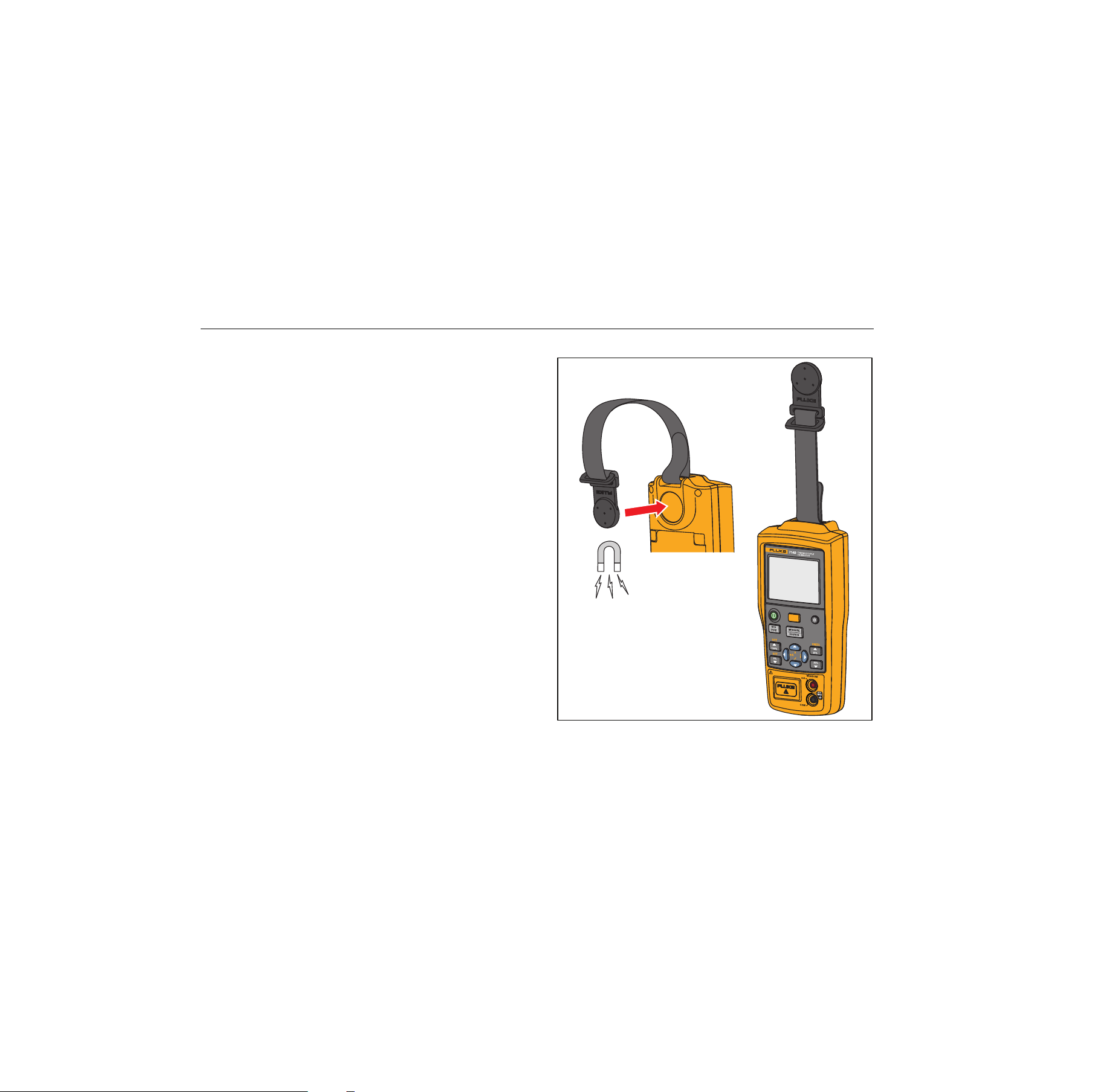
Magnet Mounting and Hanging Strap
The Product has a magnet on the rear of the unit. It is
removable. This magnet enables users to mount the
Product on metal environment and free their hands.
In addition, this Product has a hanging strap on the
magnet. Besides its hanging purpose, the strap connects
the magnet and the Product to avoid losing the magnet.
This strap is also removable.
Figure 5 shows the magnet mounting of the Product with
the hanging strap.
hrk16.eps
Figure 5. Magnet Mounting with Hanging Strap
1.888.610.7664 sales@GlobalTestSupply.com
Fluke-Direct
.com

Thermocouple Calibrator
Measure mA Current
15
Measure mA Current
Caution
To prevent impact to the measurement
function, do not use the Product to measure
current near strong magnetic fields.
To measure mA current, connect the Product to the
transmitter current terminals, as shown in Figure 7.
Measure Temperature
Use Thermocouples
The Product supports 17 standard thermocouples,
including types E, N, J, K, T, B, R, S, L, U, C, BP, XK, G,
D, P, or M. Table 6 summarizes the ranges and
characteristics of the supported thermocouples.
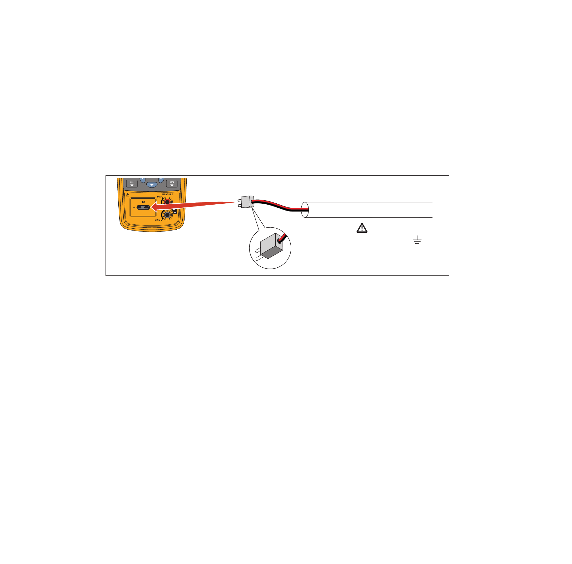
To measure temperature using a thermocouple, proceed
as follows:
1. Attach the thermocouple leads to the appropriate TC
miniplug, then to the TC input/output as shown in
Figure 6.
Note
One pin is wider than the other. Do not try to
force a miniplug in the wrong polarization.If the
Product and the thermocouple plug are at
different temperatures, wait one minute or more
for the connector temperature to stabilize after
you plug the miniplug into the TC input/output.
2. If necessary, push
for MEASURE mode.
3. Push
for the TC display. If desired, continue
pushing this key to select the desired thermocouple
type.
Set Temperature Unit
The Product allows you to select the temperature unit °C
or °F.
Push to switch to shift mode, and push to set the
temperature unit to °C or °F.
The default temperature unit is °C.
1.888.610.7664 sales@GlobalTestSupply.com
Fluke-Direct
.com

714B
Users Manual
16
Table 6. Thermocouple Types Accepted
Type
Positive Lead
Material
Specified Range
(°C)
Positive Lead (H) Color
Negative Lead
Material
ANSI* IEC**
E Chromel -250 to 1000 Purple Violet Constantan
N Ni-Cr-Si -200 to 1300 Orange Pink Ni-Si-Mg
J Iron -210 to 1200 White Black Constantan
K Chromel -200 to 1372 Yellow Green Alumel
T Copper -250 to 400 Blue Brown Constantan
B Platinum - 30 % Rhodium 600 to 1820 Gray Platinum - 6 % Rhodium
R Platinum - 13 % Rhodium -20 to 1767 Black Orange Platinum
S Platinum - 10 % Rhodium -20 to 1767 Black Orange Platinum
C
Tungsten – 5 % Rhenium 0 to 2316 White None Tungsten - 26 % Rhenium
L Iron
-200 to 900
Constantan
U Copper
-200 to 400
Constantan
BP 90.5 % Ni - 9.5 % Cr
0 to 2500
GOST
56 % Cu - 44 % Ni
Violet or Black
XK 95 % W - 5 % Re
-200 to 800
Red or Pink 80 % W - 20 % Re
1.888.610.7664 sales@GlobalTestSupply.com
Fluke-Direct
.com

Thermocouple Calibrator
Measure Temperature
17
Table 6. Thermocouple Types Accepted (cont.)
G Tungsten 100 to 2315 White Tungsten - 26 % Rhenium
D
Tungsten - 3 % Rhenium 0 to 2315 White Tungsten - 25 % Rhenium
P
Platinel 5355 0 to 1395 Platinel 7674
M
Nickel – 18 % Molybdenum -50 to 1410 Nickel - 0.8 % Cobalt
*American National Standards Institute (ANSI) device negative lead (L) is always red.
**International Electrotechnical Commission (IEC) device negative lead (L) is always white.
1.888.610.7664 sales@GlobalTestSupply.com
Fluke-Direct
.com
714B
Users Manual
18
Warning
30 V maximum to
TC Miniplug
Process Temperature
hrk14.eps
Figure 6. Measure Temperature with a Thermocouple
1.888.610.7664 sales@GlobalTestSupply.com
Fluke-Direct
.com

Thermocouple Calibrator
Simulate Thermocouples
19
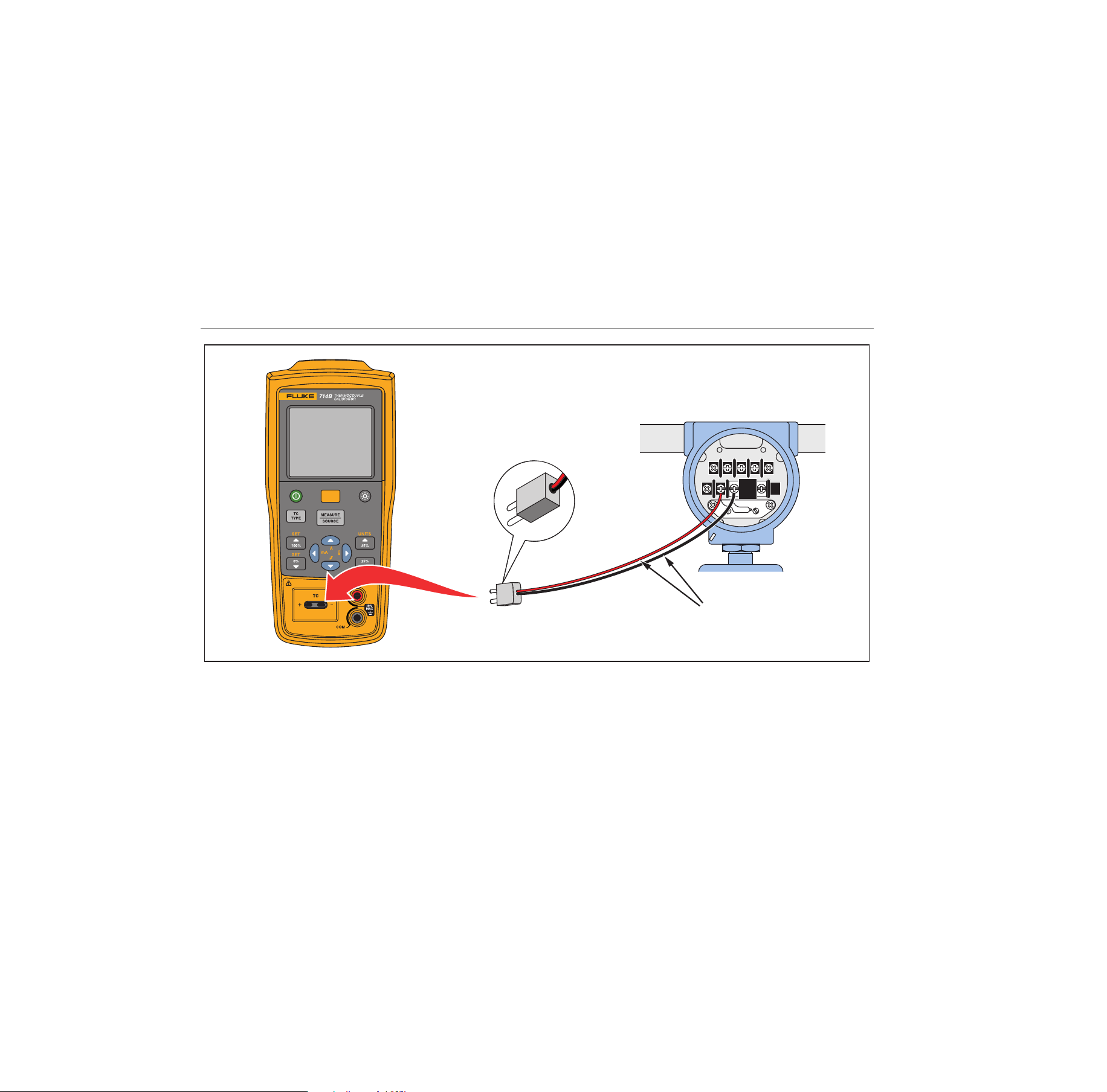
Simulate Thermocouples
Connect the Product TC input/output to the instrument
under test with thermocouple wire and the appropriate
thermocouple mini-connector (polarized thermocouple
plug with flat, in-line blades spaced 7.9 mm [0.312 in]
center to center).
Note
One pin is wider than the other. Do not try to
force a miniplug in the wrong polarization. Figure
8 shows this connection.
Proceed as follows to simulate a thermocouple:
1. Attach the thermocouple leads to the appropriate TC
miniplug, then to the TC input/output as shown in
Figure 7.
2. If necessary, push
for Source mode.
3. Push
for the TC display. If desired, continue
pushing this key to select the desired thermocouple
type or mV.
4. Enter the value you want by pushing
and .
Push and to select a different digit to edit.
1.888.610.7664 sales@GlobalTestSupply.com
Fluke-Direct
.com
714B
Users Manual
20
TEST DC PWR
+–+–
–+
TC Miniplug
Color depends
on type of TC
hrk10.eps
Figure 7. Connections for Simulating a Thermocouple
1.888.610.7664 sales@GlobalTestSupply.com
Fluke-Direct
.com

Thermocouple Calibrator
Scale mA Channel to Temperature
21
Scale mA Channel to Temperature
The Product provides a function to convert mA current
channel reading to temperature reading.
To scale mA channel to temperature:
1. Push .
2. Push .
The temperature reading shows on the display.
To switch back to mA channel:
1. Push .
2. Push .
The mA current reading shows on the display.
Note
Temperature at 4 mA = Span check 0 %
Temperature at 20 mA = Span check 100 %
Set 0 % and 100 % Output Parameters
You must set the 0 % and 100 % points before you can
use the step and ramp functions or use mA/temperature
conversion. Proceed as follows:
1. If necessary, push for Source mode.
2. Use the arrow keys to enter the value for 0 %.
3. Push and then to set the 0 % value.
4. Use the arrow keys to enter the value for 100 %.
5. Push and then to set the 100 % value.
6. Use , , , or to adjust the value.
Note
This function is only available when Source
mode is selected.
1.888.610.7664 sales@GlobalTestSupply.com
Fluke-Direct
.com

714B
Users Manual
22
Step and Ramp Modes
The Product allows you to set Step and Ramp modes for
easier check of points within the linear range in Source
mode.
To set the Step or Ramp mode:
1. Push .
2. Use and to select Step mode or Ramp mode.
The or icon shows on the Product display
accordingly.
Note
This function is only available when Source
mode is selected.
Auto Storage of Settings
The Product automatically stores the latest settings,
including the temperature unit, the linear range of mA
converting to temperature, and sensor type.
Every time you turn on the Product, it automatically
applies the last settings.
1.888.610.7664 sales@GlobalTestSupply.com
Fluke-Direct
.com
Thermocouple Calibrator
Replace the Batteries
23
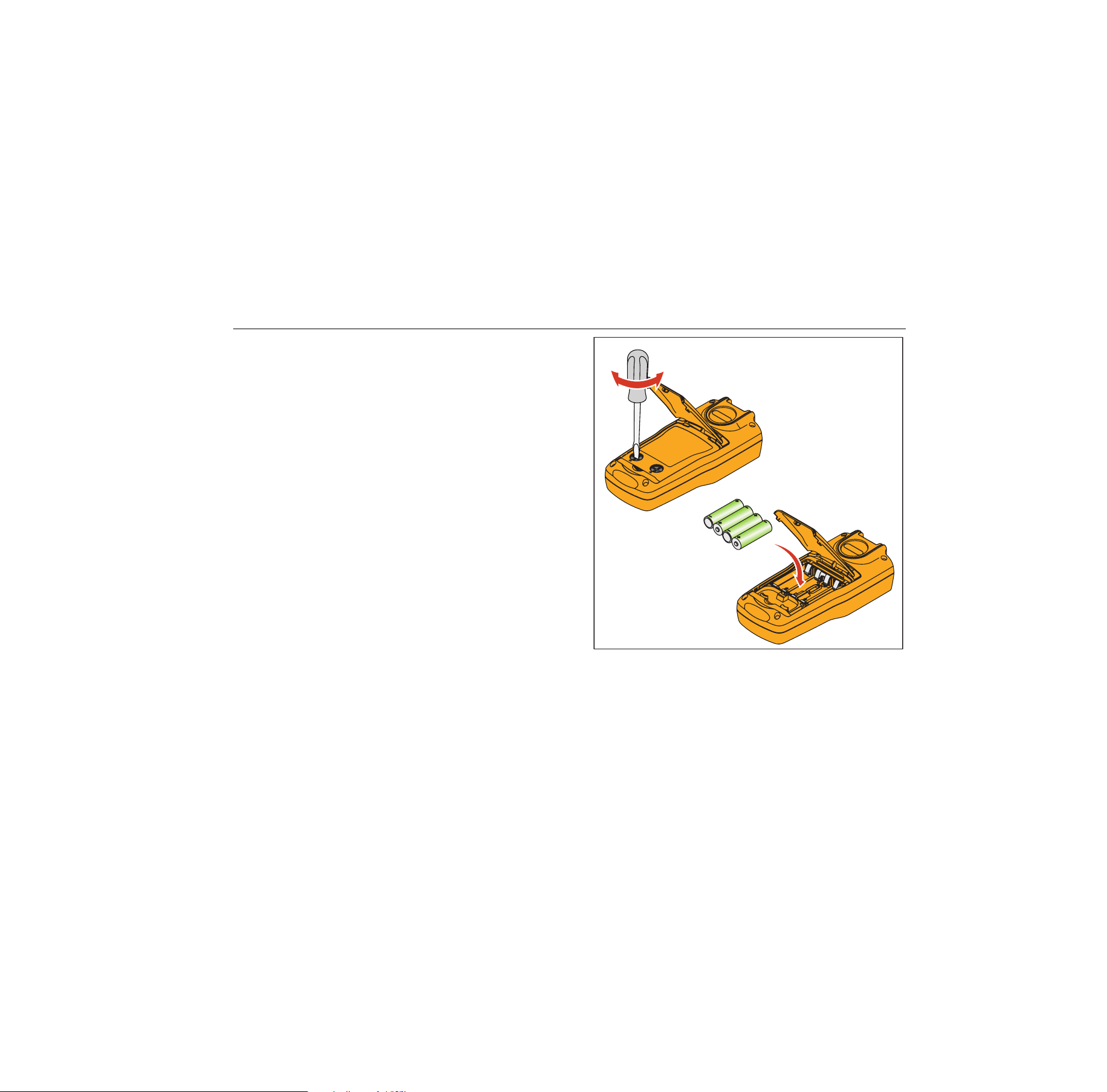
Replace the Batteries
Warning
To prevent false readings, which could lead
to possible electric shock or personal injury,
replace the batteries as soon as the low
battery indicator appears.
Figure 8 shows you how to replace the batteries.
hnh38.eps
Figure 8. Replace the Batteries
1.888.610.7664 sales@GlobalTestSupply.com
Fluke-Direct
.com

714B
Users Manual
24
Maintenance
Clean the Product
Warning
To prevent personal injury or damage to the
Product, use only the specified replacement
parts and do not allow water into the case.
Caution
To prevent damage to the plastic lens and
case, do not use solvents or abrasive
cleansers.
Clean the Product with a soft cloth dampened with water
or water and mild soap.
Service Center Calibration or Repair
Calibration, repairs, or servicing not covered in this
manual should be performed only by qualified service
personnel. If the calibrator fails, check the batteries first,
and replace them if needed.
Verify that the Product is being operated in accordance
with the instructions in this manual. If the Product is
faulty, send a description of the failure with the Product.
Be sure to pack the Product securely, using the original
shipping container if it is available. Send the equipment
postage paid and insured, to the nearest Service Center.
Fluke assumes no responsibility for damage in transit.
To locate an authorized service center, refer to “How to
Contact Fluke” at the beginning of the manual.
1.888.610.7664 sales@GlobalTestSupply.com
Fluke-Direct
.com
Thermocouple Calibrator
Maintenance
25
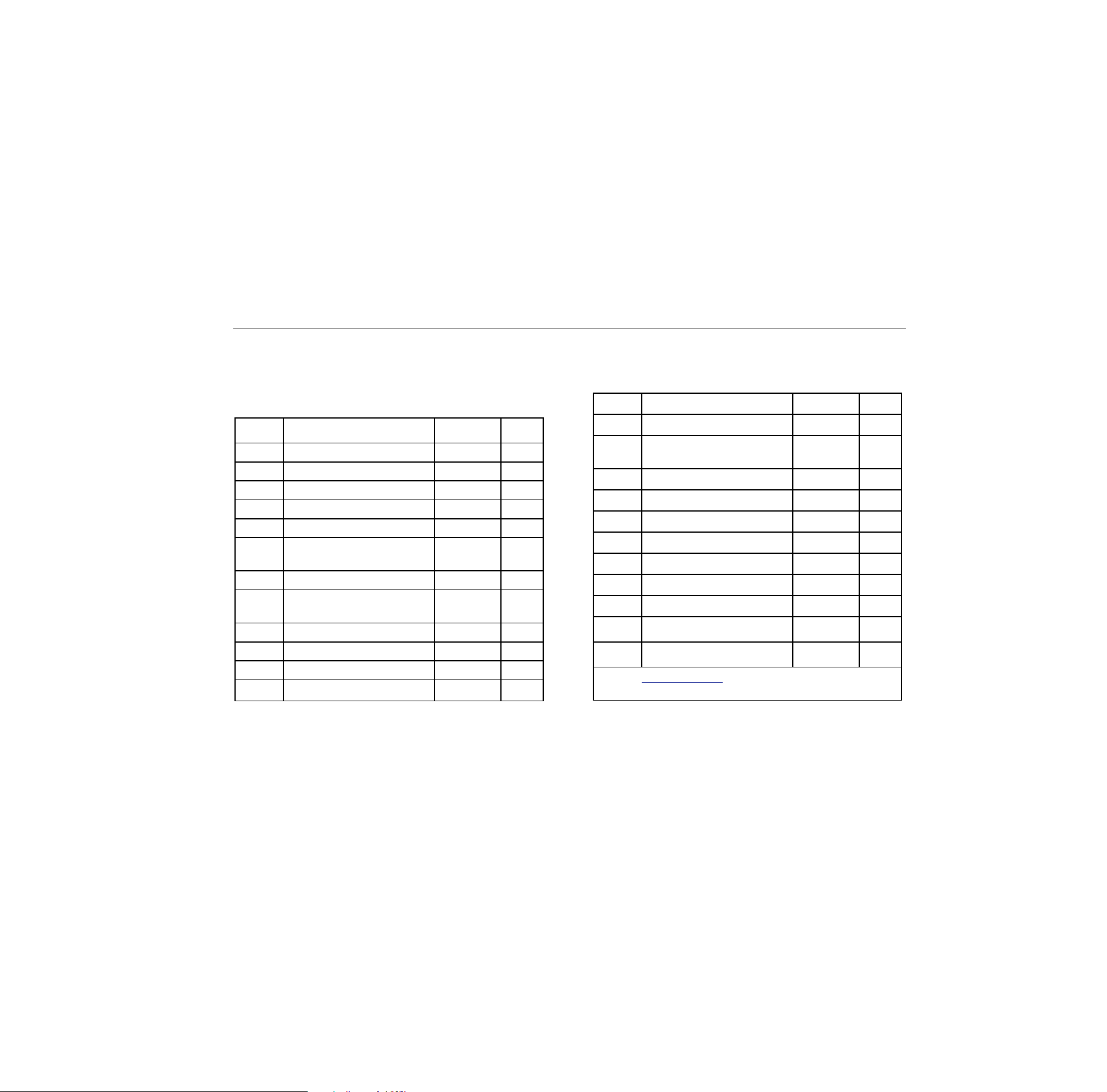
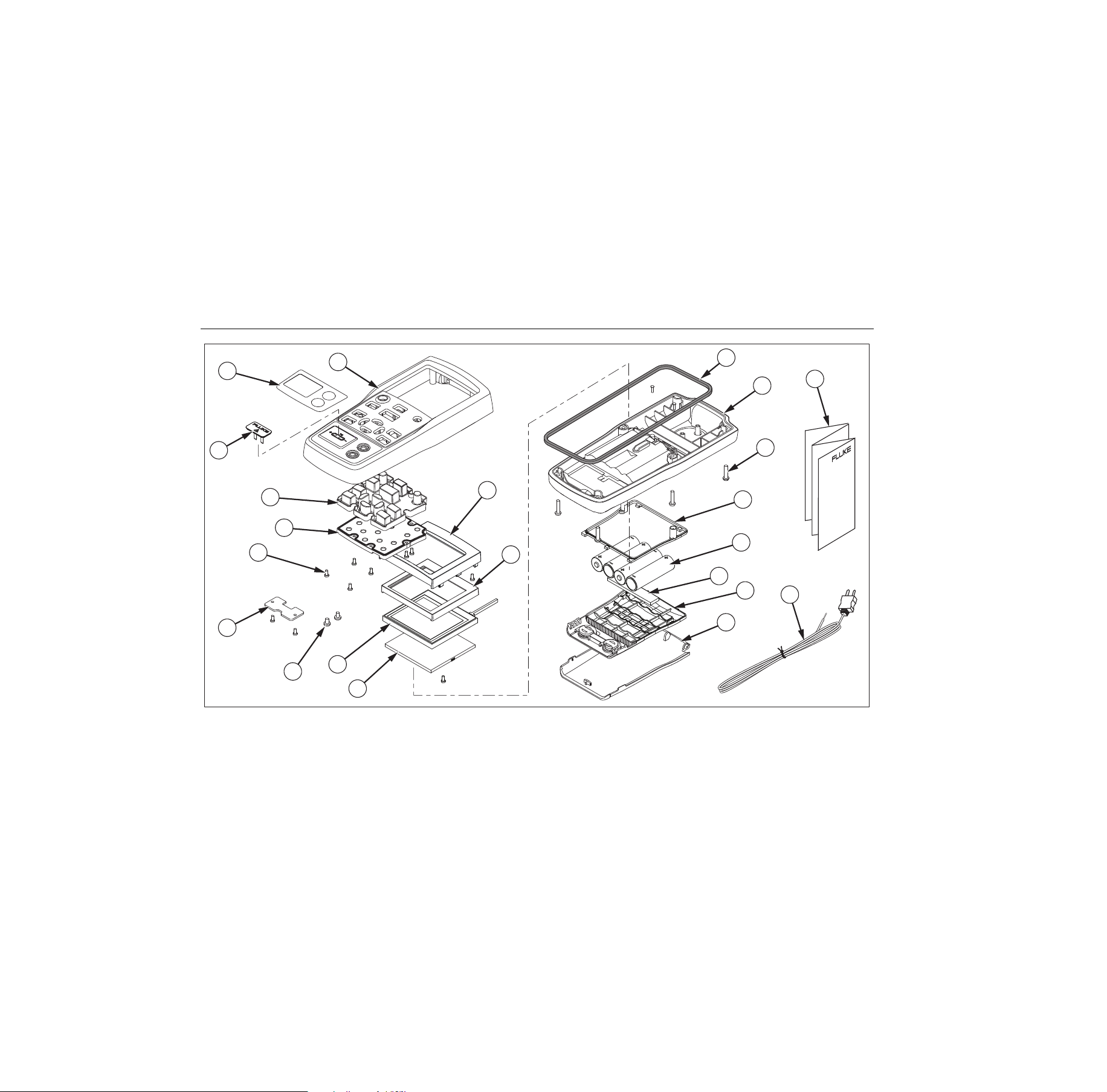
Replacement Parts
Table 7 lists the part number of each replaceable part.
Refer to Figure 9.
Table 7. Replacement Parts
Item Description PN Qty.
Case top 4307120 1
Decal on case top 4307173 1
TC cap 4369726 1
Keypad 4307158 1
Keypad support 4307112 1
Screw, M2.2 x 0.8, 5
mm, PAN, Philips
2032777 12
TC plate 4307381 1
Screw, M3-0.5 x 5 mm,
Philips
2032811 2
LCD mask 4307249 1
LCD protect rubber 4307208 1
LCD 4313462 1
Support LCD gasket 4307213 1
Case seal rubber 4307186 1
Case bottom assembly 4307079 1
Screw, M3, 13.5 mm,
PAN, Philips
2388382 6
Battery door seal rubber 4307199 1
AA battery 376756 4
Pad, battery door 4417921 1
Battery door assembly 4376901 1
Bail stand 4307093 1
Quick Reference Guide 4285039 1
TC plugkit, K type 773135 1
--
Test Leads, not shown variable
[1]
1 set
--
Alligator Clips, not shown variable
[1]
1 set
[1] See www.fluke.com for more information about the
test leads and alligator clips available for your region.
1.888.610.7664 sales@GlobalTestSupply.com
Fluke-Direct
.com
714B
Users Manual
26
5
6
1
3
2
9
10
14
13
15
21
22
16
17
18
19
20
11
8
7
12
4
hrk46.eps
Figure 9. Replacement Parts
1.888.610.7664 sales@GlobalTestSupply.com
Fluke-Direct
.com

Thermocouple Calibrator
Specifications
27
Specifications
Specifications are based on a one year calibration cycle
and apply from +18 °C to +28 °C unless stated otherwise.
All specifications assume a 5 minute warmup period.
Thermocouple mV Input
Range Resolution
Accuracy (% of Reading + Floor)
1 year 2 year
-10 mV to 75 mV 0.001 mV 0.015 % + 10 µV 0.02 % + 15 µV
Temperature coefficient: ±(0.002 % of reading + 0.002 % of range) /°C ( <18 °C or >28 °C)
Thermocouple mV Output
Range Resolution
Accuracy (% of Output + Floor)
1 year 2 year
-10 mV to 75 mV 0.01 mV 0.015 % + 10 µV 0.02 % + 15 µV
Temperature Coefficient: ± (0.002 % of output + 0.002 % of range) /°C ( <18 °C or >28 °C)
Thermocouple mA Input
Range Resolution
Accuracy (% of Reading + Floor)
1 year 2 year
0 mA to 24 mA 0.001 mA 0.01 % + 2 µA 0.02 % + 4 µA
Temperature Coefficient: ± (0.002 % of output + 0.002 % of range) /°C ( <18 °C or >28 °C)
1.888.610.7664 sales@GlobalTestSupply.com
Fluke-Direct
.com

714B
Users Manual
28
Thermocouple Input and Output
TC Type Range
Measure (°C) Source (°C)
1 year 2 year 1 year 2 year
E
-250 to 200 1.3 2.0 0.6 0.9
-200 to -100 0.5 0.8 0.3 0.4
-100 to 600 0.3 0.4 0.3 0.4
600 to 1000 0.4 0.6 0.2 0.3
N
-200 to -100 1.0 1.5 0.6 0.9
-100 to 900 0.5 0.8 0.5 0.8
900 to 1300 0.6 0.9 0.3 0.4
J
-210 to -100 0.6 0.9 0.3 0.4
-100 to 800 0.3 0.4 0.2 0.3
800 to 1200 0.5 0.8 0.3 0.3
K
-200 to -100 0.7 1.0 0.4 0.6
-100 to 400 0.3 0.4 0.3 0.4
400 to 1200 0.5 0.8 0.3 0.4
1200 to 1372 0.7 1.0 0.3 0.4
T
-250 to -200 1.7 2.5 0.9 1.4
-200 to 0 0.6 0.9 0.4 0.6
0 to 400 0.3 0.4 0.3 0.4
B
600 to 800 1.3 2.0 1.0 1.5
800 to 1000 1.0 1.5 0.8 1.2
1000 to 1820 0.9 1.3 0.8 1.2
1.888.610.7664 sales@GlobalTestSupply.com
Fluke-Direct
.com

Thermocouple Calibrator
Specifications
29
R
-20 to 0 2.3 2.8 1.2 1.8
0 to 100 1.5 2.2 1.1 1.7
100 to 1767 1.0 1.5 0.9 1.4
S
-20 to 0 2.3 2.8 1.2 1.8
0 to 200 1.5 2.1 1.1 1.7
200 to 1400 0.9 1.4 0.9 1.4
1400 to 1767 1.1 1.7 1.0 1.5
C
0 to 800 0.6 0.9 0.6 0.9
800 to 1200 0.8 1.2 0.7 1.0
1200 to 1800 1.1 1.6 0.9 1.4
1800 to 2316 2.0 3.0 1.3 2.0
L
-200 to -100 0.6 0.9 0.3 0.4
-100 to 800 0.3 0.4 0.2 0.3
800 to 900 0.5 0.8 0.2 0.3
U
-200 to 0 0.6 0.9. 0.4 0.6
0 to 600 0.3 0.4 0.3 0.4
BP
0 to 1000 1.0 1.5 0.4 0.6
1000 to 2000 1.6 2.4 0.6 0.9
2000 to 2500 2.0 3.0 0.8 1.2
XK
-200 to 300 0.2 0.3 0.2 0.5
300 to 800 0.4 0.6 0.3 0.6
G
100 to 300 1.6 2.4 1.2 1.8
300 to 1500 1.0 1.5 1.0 1.5
1500 to 2315 2.0 3.0 1.6 2.4
1.888.610.7664 sales@GlobalTestSupply.com
Fluke-Direct
.com

714B
Users Manual
30
D
0 to 300 1.6 2.4 1.2 1.8
300 to 1500 1.0 1.5 1.0 1.5
1500 to 2315 2.0 3.0 1.6 2.4
P
0 to 1000 1.6 2.4 0.6 0.9
1000 to 1395 2.0 3.0 0.8 1.2
M
-50 to 100 1.0 1.5 0.4 0.6
100 to 1000 1.6 2.4 0.6 0.9
1000 to 1410 2.0 3.0 0.8 1.2
1) Sensor inaccuracies not included.
2) Accuracy with external cold junction; for internal junction add 0.2 °C
3) Temperature scale: ITS-90
Compensation: NIST Monograph 175 for B, R, S, E, J, K, N, T. DIN 43710 for L, U. GOST P 8.585-2001 (Russia) for
BP and XK. ASTM E988-96 for C. ASTM E1751/E1751M − 09ԑ1 for G, D, P, M
4) Resolution: 0.1 °C
5) Temperature Coefficient: 0.05 °C/°C ( <18 °C or >28 °C )
0.07 °C/°C for C type >1800 °C and for BP type >2000 °C
1.888.610.7664 sales@GlobalTestSupply.com
Fluke-Direct
.com

Thermocouple Calibrator
General Specifications
31
General Specifications
Maximum voltage applied between any
terminal and earth ground or between
any two terminals:
30 V
Operating temperature -10 °C to 50 °C
Storage temperature -20 °C to 60 °C
Operating altitude 2,000 meters
Storage altitude 12,000 meters
Relative Humidity (% RH operating
without condensation)
Non condensing
90 % (10 °C to 30 °C)
75 % (30 °C to 40 °C)
45 % (40 °C to 50 °C)
(Without condensation)
Vibration Requirements MIL-T-28800E, Class 2
Drop Test Requirements 1 meter
IP Rating IEC 60529: IP52 (with TC cap)
Electromagnetic Environment IEC 61326-1, Portable
Safety IEC 61010-1, Max 30 V to earth, Pollution Degree 2
Power Supply 4 AA alkaline batteries/NEDA code: 15A, IEC code: LR6
Size (H x W x L) 52.5 x 84 x 188.5 mm
Weight 515 g
1.888.610.7664 sales@GlobalTestSupply.com
Fluke-Direct
.com