Loading ...
Loading ...
Loading ...
17
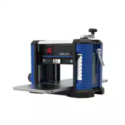
ADJUSTING THE IN-FEED AND
OUT-FEED TABLES
Your unit has been factory set with careful table alignment to help
eliminate snipe. If your unit loses its adjustment and causes snipe,
you can adjust the in-feed and out-feed tables to minimize this
condition.
1. Raise the cutterhead.
2. Place a dime
A
Figure 24 at each end of the Wear
Table (in-feed and out-feed).
3. Place a straight edge
B
across the two dimes. Extend
the straight edge past the edges of the in-feed and
out-feed tables.
4. If your tables are properly adjusted, the straight edge
will touch both of the dimes and both the edges of the
tables.
5. If your table needs adjustment, loosen the lock
nuts
D
Figure 25 on the table height-adjustment
screws
C
. Adjust the screws up or down to achieve
the desired table height.
6. Make sure that both height-adjustment screws contact
the bottom of the table after adjustment.
7. Re-tighten lock nuts
C
.
FIGURE 24
FIGURE 25
MAINTENANCE/ADJUSTMENTS
A
B
D
C
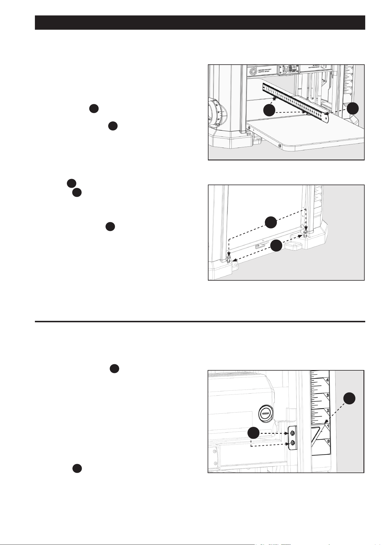
The depth adjustment scale
F4
, Figure 26, on your planer is
set at the factory. However, with extended use, the depth
adjustment scale could show an incorrect measurement. To
check the depth adjustment scale:
1. Plane a piece of scrap wood, noting the measurement
on the depth adjustment scale.
2. Measure the nished thickness of the workpiece. When
measuring the thickness, measure away from the ends.
Beware of snipe. Measuring the snipe could result in
inaccurate measurements.
3. If the thickness of the workpiece does not match the
reading on the depth adjustment scale, loosen the two
screws
B
on the red indicator. Adjust the pointer up
or down until its reading matches the finished
thickness of the workpiece. Securely re-tighten the
screws.
CALIBRATING THE INDICATOR
ARROW
FIGURE 26
F4
B
Loading ...
Loading ...
Loading ...