
Loading ...
Loading ...
Loading ...
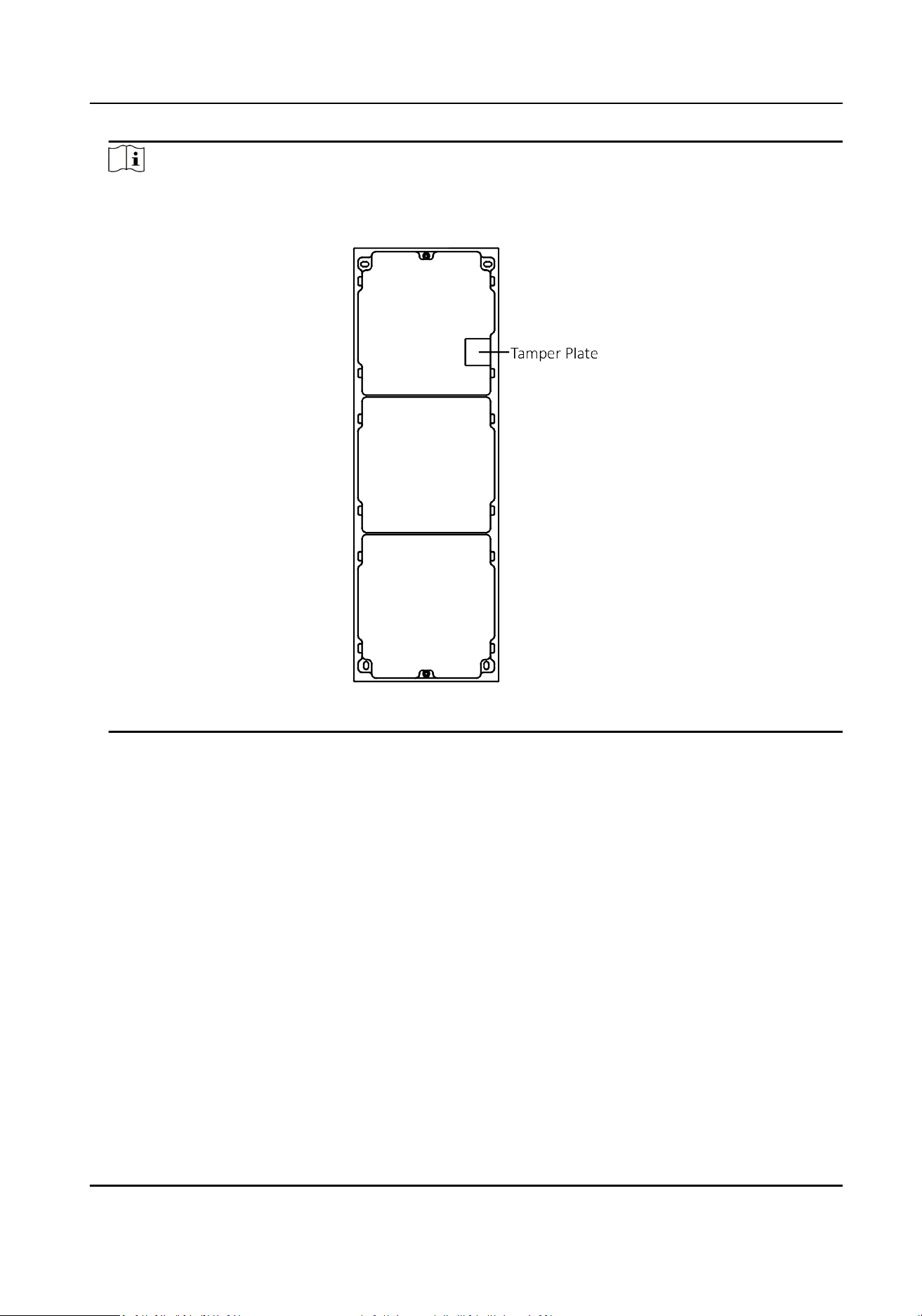
Note
The mounng frame should be placed exactly as shown below for this step. The tamper plate
should be at the low right of the rst grid.
Figure 4-31 Mounng Frame
5.
Thread the module-connecng line across the thread holes of the frame. Pass the main unit
connecng line across the thread hole to the top grid.
DS-KD8003 Series Module Door Staon User Manual
43
Loading ...
Loading ...
Loading ...