Loading ...
Loading ...
Loading ...
EXTENSION WINGS
For Models with Three Extension Wings
1. Next attach the left side extension wing (3) to the front
and rear rails using four (5/16-18 x 1 1/8”) at head
screws, (5/16”) lock washers, and (5/16-18) hex ange
nuts. See Figure (9a)
2. Attach the left side extension wing (3) to the side of the
saw table using three (5/16-18 x 7/8”) hex head screws
w/ spring washers. See Figure (9b)
3. Lay the two remaining wings upside down on the saw
table. Place the two wings adjacent to each other,
so the holes patterns match. Fasten the two wings
together using three (5/16-18 x 7/8”) hex head screws
w/ spring washers and (5/16-18) hex ange nuts.
4. Turn the two wings fastened together over and fasten
them to side of the saw table using three (5/16-18 x
7/8”) hex head screws w/ spring washers. See Figure
(8)
Note: Use a ruler to make sure the top edges of the wings are
flush with the top of the tabletop. See Figure (7)
Note: There are two set screws for the cast iron extension
wing. The set screws are used to adjust the level. See Figure
(8)
FIGURE 7
FIGURE 8
EXTENSION WINGS
For Models with Two Extension Wings and a Wood
Extension Table
1. Attach the extension wings (3), to the Front and Rear
rails using four (5/16-18 x 1 1/8”) at head screws,
(5/16”) lock washers, and (5/16-18) hex ange nuts.
See Figure (9)
2. Attach the extension wings (3) to the table using three
(5/16-18 x 7/8”) hex head screws w/ spring washers for
each wing. See Figure (9)
Note: Use a ruler to make sure the top edges of the wings are
flush with the top of the tabletop. See Figure (9)
Note: There are two set screws for the cast iron extension
wing. The set screws are used to adjust the level. See Figure
(8)
3. Proceed to rail assembly.
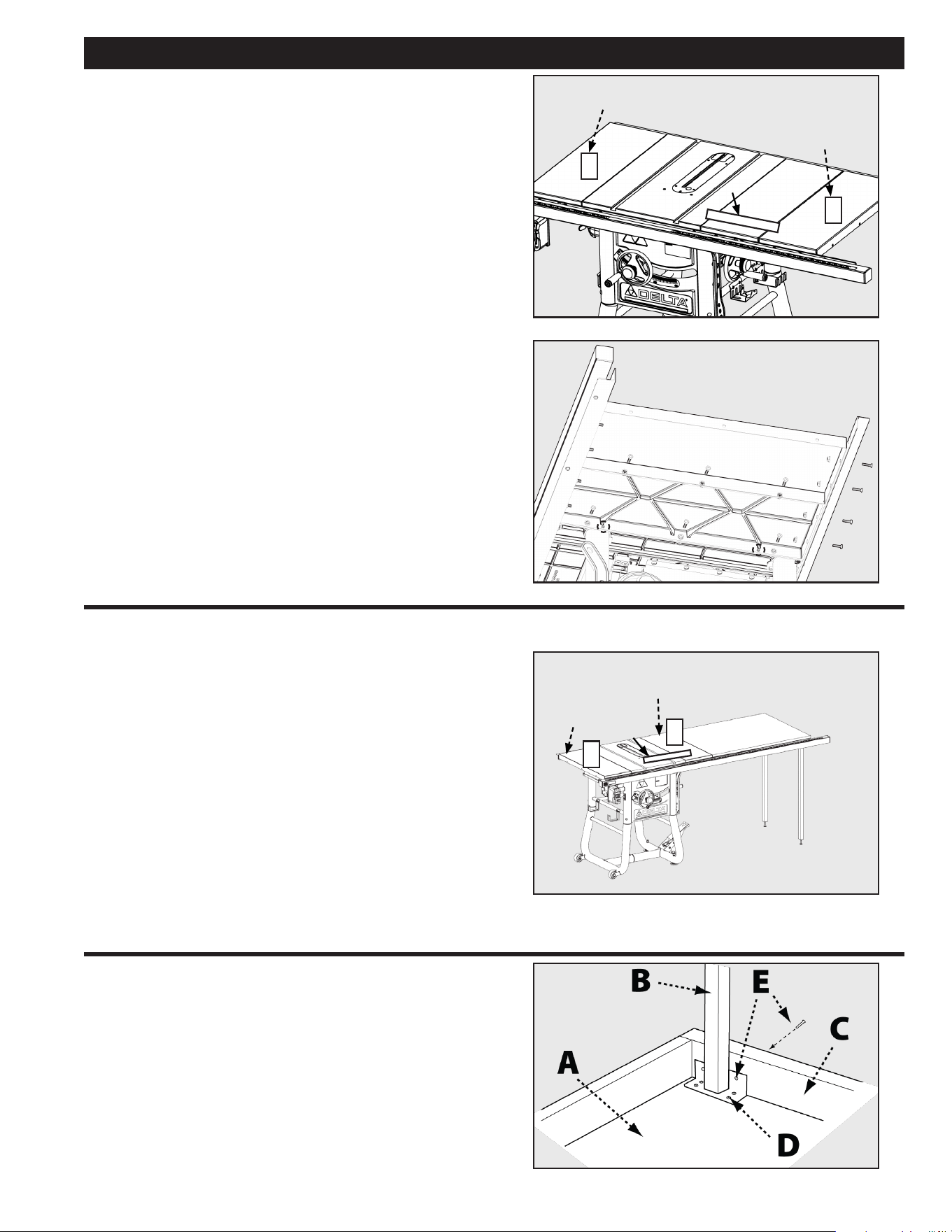
FIGURE 9
WOOD EXTENSION TABLE
52” rip capacity models only
1. Lay the wood table (A) upside down on oor or bench.
2. Position legs (B) in corner as shown (Fig. 10) the
vertical wall of the angle plate on the leg should be
against the end wood wall (C) of the table.
3. Fasten the legs to the table board with eight #8 x 3/4”
self-tapping screws (D).
FIGURE 10
ASSEMBLY
3
3
3
3
LEFT EXTENSION LEFT EXTENSION
WING WING
LEFT EXTENSION
WING
RIGHT EXTENSION RIGHT EXTENSION
WING WING
RIGHT EXTENSION
WING
RULER RULER
RULER
13
Loading ...
Loading ...
Loading ...