Loading ...
Loading ...
Loading ...
B
A
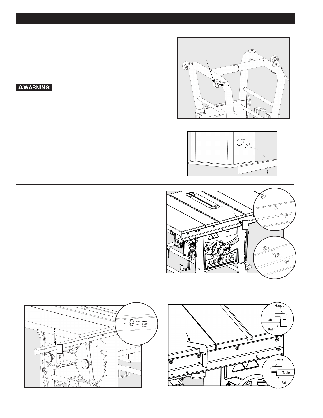
FIGURE 3
FRONT AND REAR RAILS
1. Attach the front rail (1) to the table front using two
(5/16-18 x 1 1/8”) at head screws and two (5/1618)
hex ange nuts. (Fig. 4a) One (5/16”) conical grounding
washer should be installed directly in front of one of the
screw heads. (Fig. 4b)
2. Attach the rear rail (2) to the table back using two
(5/16-18 x 7/8”) at head screws w/ spring washer and
two (5/16-18) hex ange nuts. (Fig. 6) One (5/16”) at
star grounding washer should be installed directly in
front of one of the screw heads. (Fig. 6a)
Note: use the two aligning holes which are spaced 16” apart
to align the front and rear rails to the table aligning holes
which are also spaced 16” apart.
3. Use supplied rail alignment gauge to ensure the rail is
the proper distance from the top of the table at each
side of the cast iron table. (Fig. 5)
FIGURE 4
FIGURE 5
FIGURE 6
ASSEMBLY
FIXED WHEELS AND STATIONARY FEET
1. Attach the two xed wheels (A) to the two left leg,
opposite the pivot caster, using the M8 x 53mm Carriage
Screw as in Figure 2.
2. Lay a scrap piece of 2x4 in back of the saw, as shown
in Figure 3, to prevent damage to the dust chute when
righting the saw.
3. Stand the saw right side up.
The machine is heavy, two people are
required to stand the machine up.
4. Modify the two Adjustable Feet (C) by screwing them
in and out of the leg. The feet may be adjusted to level
the saw and locked in place by tightening the M12 nut
on the top. See Figure 2.
FIGURE 2
4a
4b
1
2
Front RailFront Rail
Rear Rail
GAUGE
FRONT
BACK
6a
12 13
Loading ...
Loading ...
Loading ...