Loading ...
Loading ...
Loading ...
Page 8 • JL Audio, Inc., 2020 Continued on Next Page
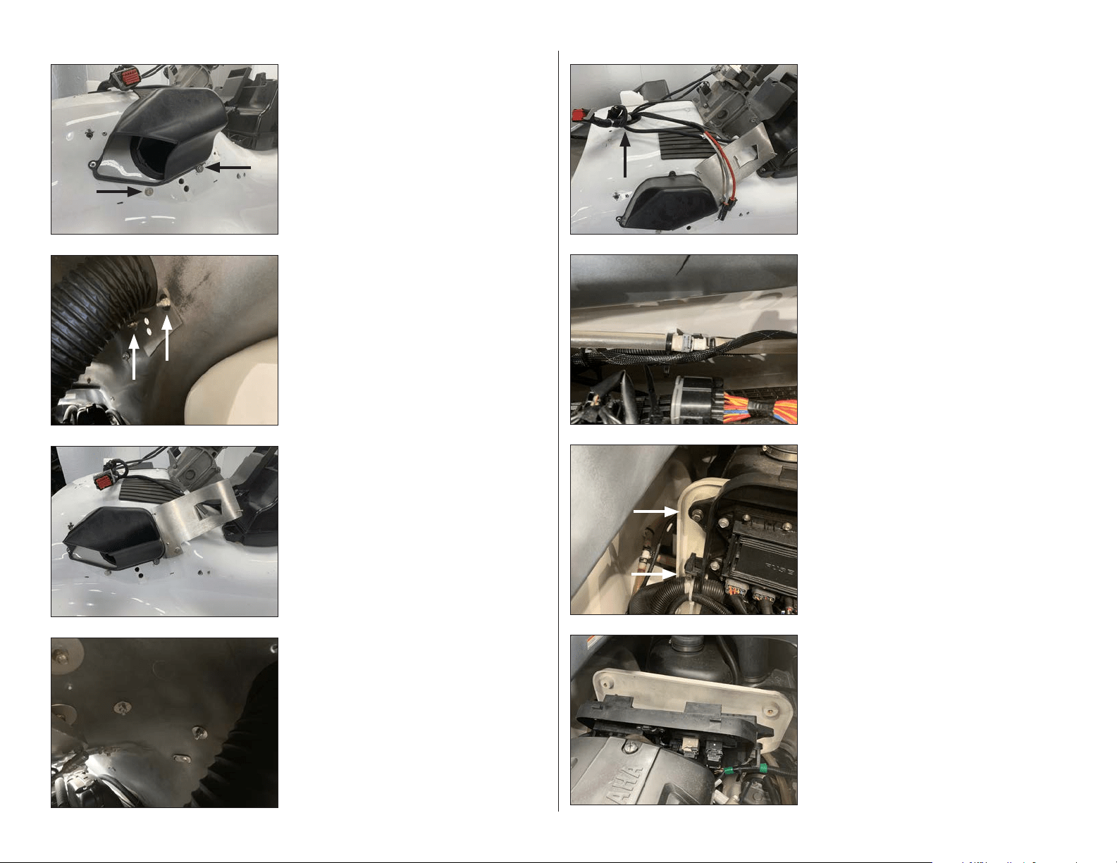
STEP 40
Pull the factory junction box panel off of the
firewall.
STEP 39
Remove the two bolts from the side of the
factory junction box panel. Repeat for the
opposite side.
STEP 38
Route the Power Harness down the inside of
the hull on the starboard side, toward the
battery. Use Cable Ties to secure the Power
Harness to the factory wiring.
STEP 37
Loosen the factory cable tie below the console
grommet on the hull, and pass the Power
Harness down through the grommet until
approximately 19” of the connector end remain
exposed above.
STEP 36
From inside the hull, secure the Amplifier
Bracket to the vessel using a 1/4” Oversized
Flat Washer and a 1/4 - 20 Nylon Insert Locknut
over each 1/4 - 20 x 1” Hex Cap Screw, and fully
tighten.
STEP 35
Align the Amplifier Bracket to the vessel. Slide
a 1/4” Flat Washer over each of two 1/4 - 20 x 1”
Hex Cap Screws. Apply Loctite® Threadlocker
to each, and pass an assembly through the
mounting holes in the Amplifier Bracket,
through the holes drilled in Steps 27 & 29.
STEP 34
From inside the hull, align the outer holes in a
Back Plate with the hardware installed in the
previous step. Ensure the curved side of the
Back Plate is oriented upward. Secure the Back
Plate using a 1/4” Oversized Flat Washer and a
1/4 - 20 Nylon Insert Locknut over each 1/4 - 20
x 1” Hex Cap Screw, and fully tighten.
Repeat Steps 30-34 on the starboard side.
STEP 33
Slide a 1/4” Flat Washer over each of two
1/4 - 20 x 1” Hex Cap Screws. Apply Loctite®
Threadlocker to each, and pass an assembly
through each of the indicated holes drilled in
Steps 24 & 32.
SLPK-YA-19FXC / SLPK-YA-19FXC-SUB INSTR_SKU# 011531
Loading ...
Loading ...
Loading ...