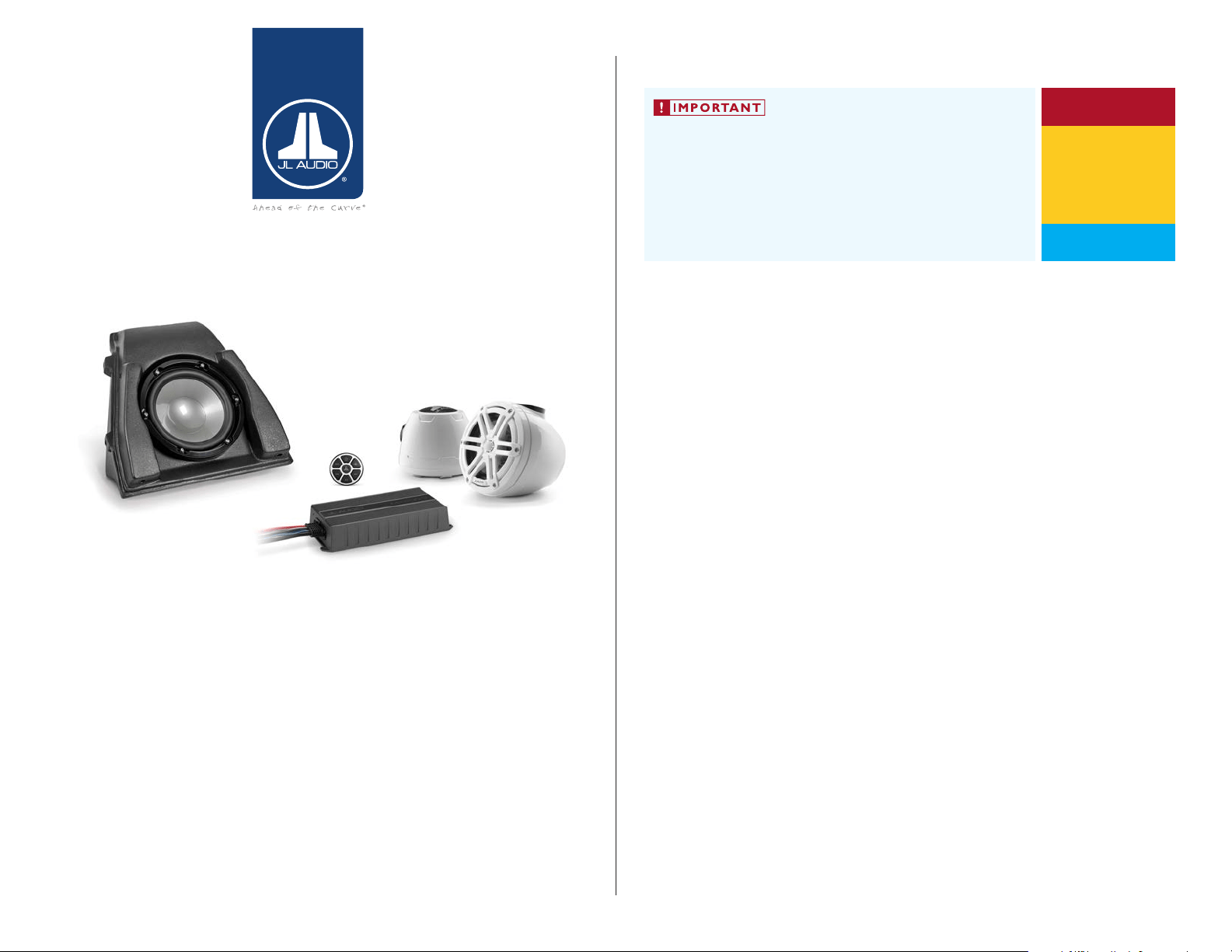
INSTALLATION GUIDE
for the
SLPK-YA-19FXC
SKU# 94670 & 94671
&
SLPK-YA-19FXC-SUB
SKU# 94674
2019-Up Yamaha FX
Thank you for choosing a JL Audio SlamPak™ for your marine sound system.
With proper installation, your new marine audio sound system
will deliver years of listening pleasure.
We strongly recommend that you have your new SlamPak™ installed by your
authorized JL Audio dealer. The installation professionals employed by your
dealer have the necessary tools and experience to disassemble and reassemble
your vessel properly. If you prefer to perform your own installation, please read
this installation guide completely before beginning the process.
If you choose to perform the installation yourself, it is absolutely
vital that the SlamPak™ be properly mounted to the vessel
according to these instructions. Failure to mount the enclosures
properly presents two problems:
1) A loose enclosure presents a serious safety hazard in the event of a
collision, rollover, or sudden deceleration.
2) The sub-bass performance will suffer due to the movement of the
enclosure caused by the force exerted by the woofer(s).
INSTALLATION
DIFFICULTY:
ESTIMATED TIME:
34 HOURS
Continued on Next Page
5
5
OUT
OF
SlamPak
™
SLPK-YA-19FXC / SLPK-YA-19FXC-SUB INSTR_SKU# 011531
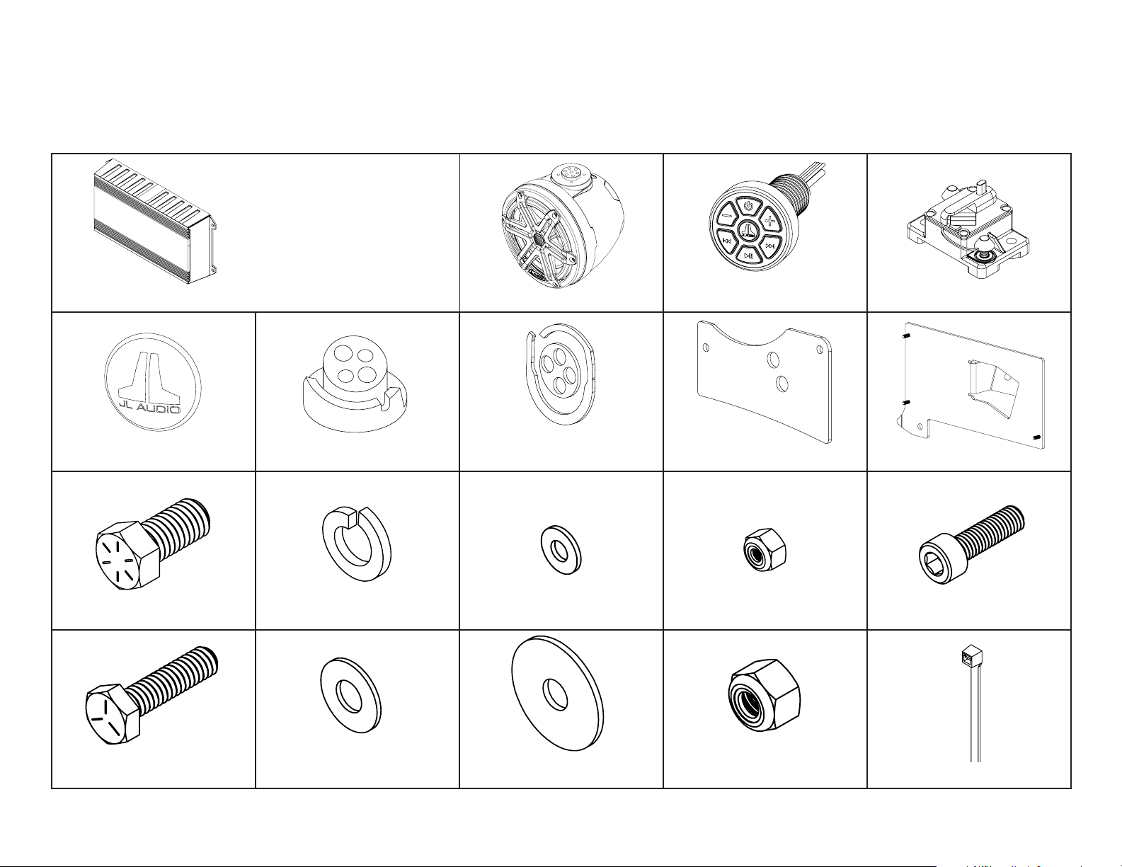
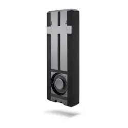
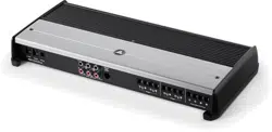
MX600/3 Amplifier (x1) VEX Speaker Enclosure (x2) 50A Circuit Breaker (x1)
Rear Logo Appliqué (x2)
Port VEX Adaptor (x1)
Starboard VEX Adaptor (x1)
Port VEX Adaptor Gasket (x1)
Starboard VEX Adaptor Gasket (x1) Back Plate (x2) Amplifier Bracket (x1)
7/16 - 14 x 7/8” Stainless Steel
Hex Head Bolt (x4)
7/16” Stainless Steel
Split Lock Washer (x4)
8-32 Stainless Steel
Flat Washer (x3)
8-32 Stainless Steel
Locknut (x3)
1/4 - 20 x 1” Stainless Steel
Hex Cap Screw (x8)
1/4” Stainless Steel
Flat Washer (x10)
1/4” Stainless Steel
Oversized Flat Washer (x6)
1-4 - 20 Stainless Steel
Nylon Insert Locknut (x8) 11” Cable Ties (x10)
INCLUDED HARDWARE
Continued on Next Page
Page 2 • JL Audio, Inc., 2020
SLPK-YA-19FXC / SLPK-YA-19FXC-SUB INSTR_SKU# 011531
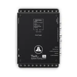
SLPK-YA-19FXC Equipment and Hardware
M6 - 1 x 20mm Stainless Steel
Socket Cap Screw (x4)
MBT-CRXv2
Bluetooth Controller (x1)
NOTE: For optimum performance
and reliability, all amplifier controls
have been preset for this SlamPak™
and sealed beneath the control
panel cover. No further adjustment
is necessary.
INCLUDED HARDWARE
Continued on Next Page
Page 3 • JL Audio, Inc., 2020
SLPK-YA-19FXC / SLPK-YA-19FXC-SUB INSTR_SKU# 011531
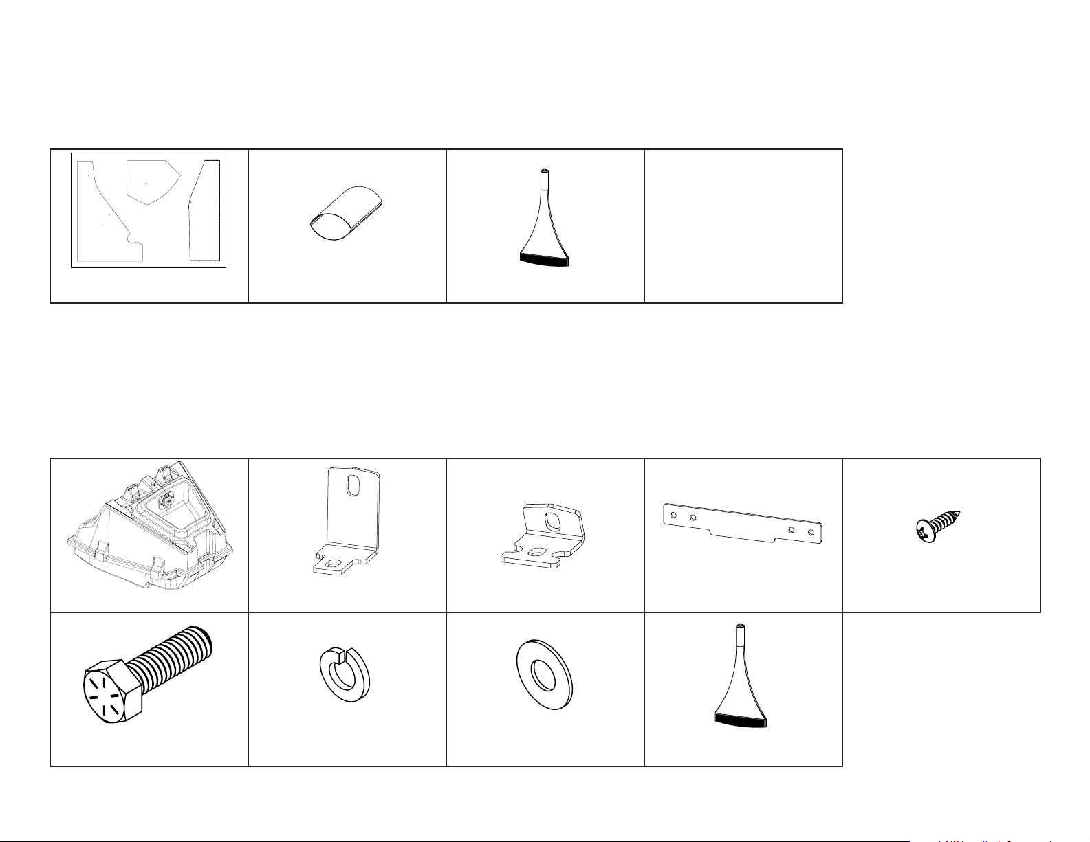
SLPK-YA-19FXC Equipment and Hardware (cont.)
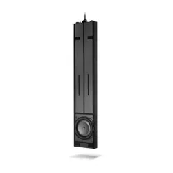
SLPK-YA-19FXC-SUB Equipment and Hardware
Clear Sheet
Drilling Template (x1)
NOT SHOWN
Power Harness (x1)
Amplifier Harness (x1)
1.5’ 2-Channel
RCA Interconnect (x1)
8 AWG Power Cable Extension (x1)
Subwoofer Enclosure (x1) Long Bracket (x2) Short Bracket (x2) Latch Bracket (x1)
#6 x 1/2” Stainless Steel
Pan Head Screw (x4)
5/16 - 18 x 1” Stainless Steel
Hex Head Bolt (x4)
5/16” Stainless Steel
Split Lock Washer (x4)
5/16” Stainless Steel
Flat Washer (x4) Loctite® Threadlocker (x1)
Loctite® Threadlocker (x1)
2-Pack 1” Heat Shrink (x1)
2-Pack 2” Heat Shrink (x2)
Page 4 • JL Audio, Inc., 2020 Continued on Next Page
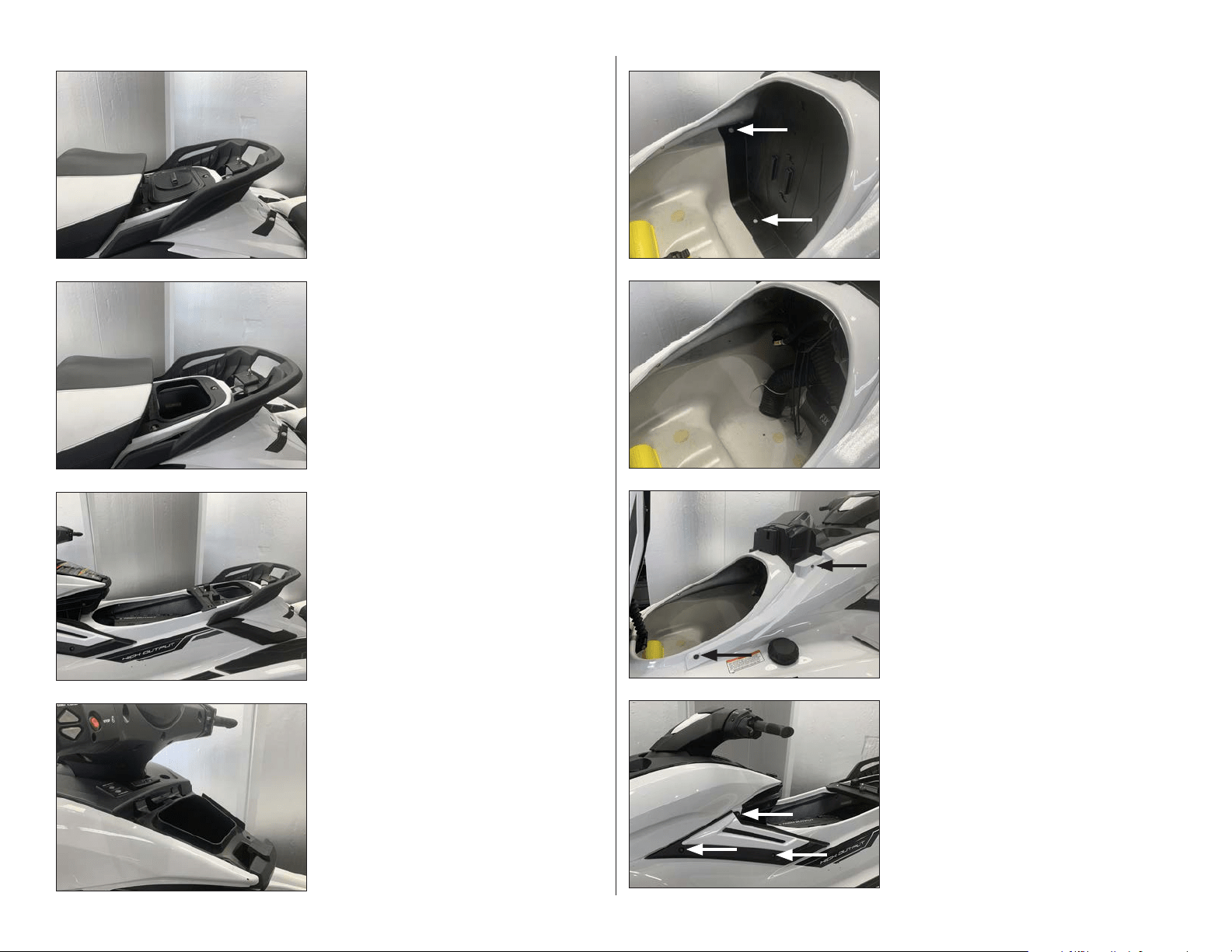
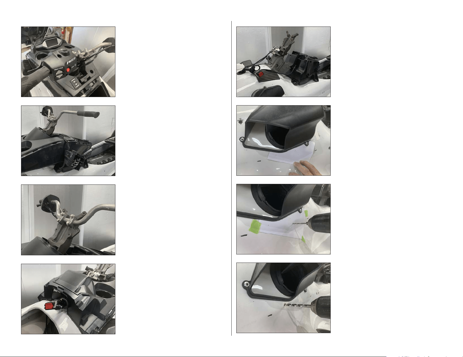
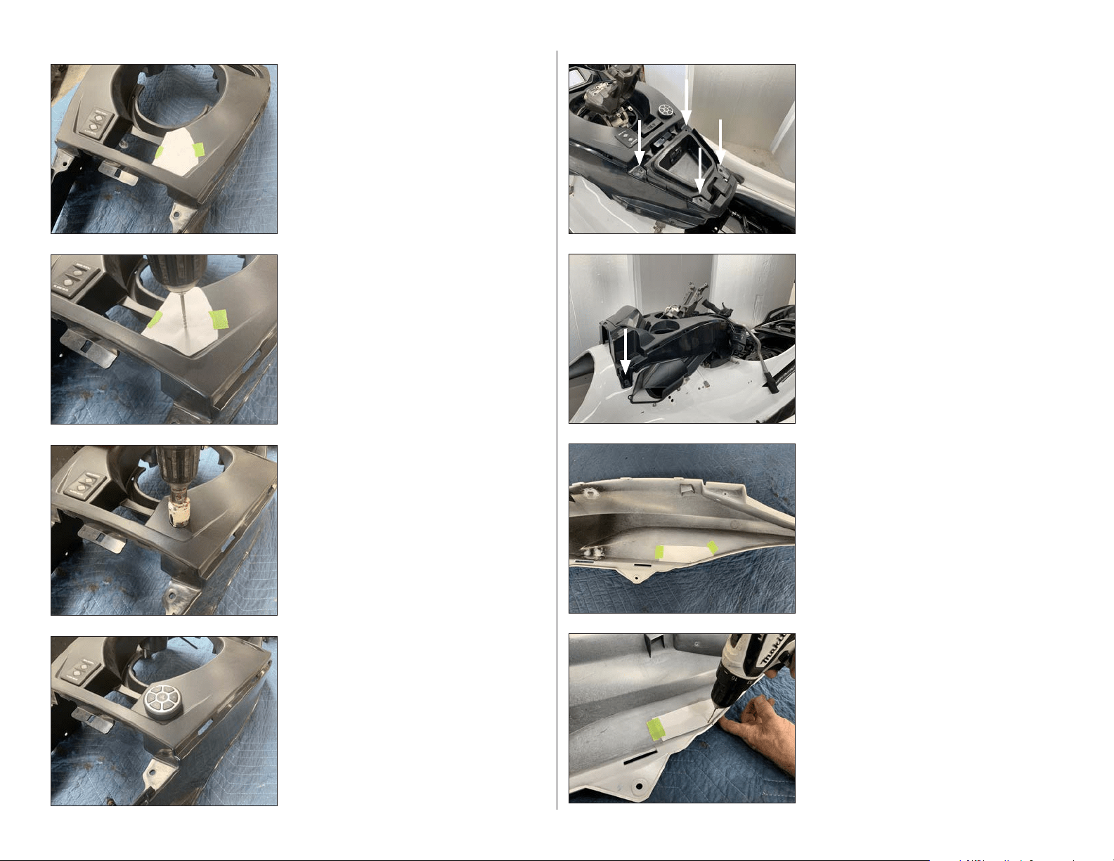
STEP 8
Remove the three indicated screws from the
accent panel on the port side, then remove the
nut from the inside of the hull.
STEP 7
Remove the indicated front bolt and nut and
the rear screw from the body panel on the port
side.
STEP 6
The lower access panel has been removed.
STEP 5
Unlatch and lift the lid. Remove the two
indicated push clips from the starboard side
of the lower access panel. Repeat for the two
push clips on the port side, and remove the
panel.
STEP 4
Open the center storage compartment, and
carefully unclip and remove the storage
compartment lid.
STEP 3
Remove the front seat section from the vessel.
STEP 2
Remove the under seat locker.
STEP 1
NOTE: This manual includes installation
steps for the SLPK-YA-19FXC speaker kit and
the SLPK-YA-19FXC subwoofer enclosure
add-on. Please take the time to read this
manual thoroughly to familiarize yourself
with the installation steps for your
application.
Unlatch and remove the rear seat section from
the vessel.
SLPK-YA-19FXC / SLPK-YA-19FXC-SUB INSTR_SKU# 011531

Page 5 • JL Audio, Inc., 2020 Continued on Next Page
STEP 16
Remove the four screws from around the
steering column cover panel.
STEP 15
Remove the lower handle bar cover panel from
the vessel.
STEP 14
Remove the upper handle bar cover panel from
the vessel.
STEP 13
Remove the eleven screws from the lower
handle bar cover panel.
STEP 12
Remove the two bolts from under the upper
access panel, and remove the panel from the
vessel.
STE P 11
Remove the body panel from the vessel.
Remove the indicated screw from the front of
the console, and repeat for the screw on the
opposite side.
Repeat Steps 7-11 for the starboard side.
STEP 10
Remove the two indicated screws from the top
of the body panel on the port side.
STEP 9
Remove the accent panel from the vessel.
SLPK-YA-19FXC / SLPK-YA-19FXC-SUB INSTR_SKU# 011531
Page 6 • JL Audio, Inc., 2020 Continued on Next Page
STEP 24
Enlarge the forward hole using a 1/4” drill bit.
STEP 23
Using a 1/16” drill bit, carefully drill through
each of the three marks on Template A and into
the hull.
Carefully remove Template A from the vessel.
STEP 22
Carefully cut Template A from the clear sheet
on the indicated line.
Align Template A with the bottom of the
induction box on the port side, and tape it into
position.
STEP 21
Carefully remove the console from the vessel
by guiding the handle bar and throttle control
through the center opening.
STEP 20
From under the console, unplug the main
harness and the Menu Scroll / Alarm Mute
switch.
STEP 19
Remove the four handle bar bolts, and carefully
set the handle bar to the side.
STEP 18
Remove the throttle control from the handle
bar and carefully set it to the side.
STEP 17
Remove the four screws from the throttle
control.
SLPK-YA-19FXC / SLPK-YA-19FXC-SUB INSTR_SKU# 011531
Page 7 • JL Audio, Inc., 2020 Continued on Next Page
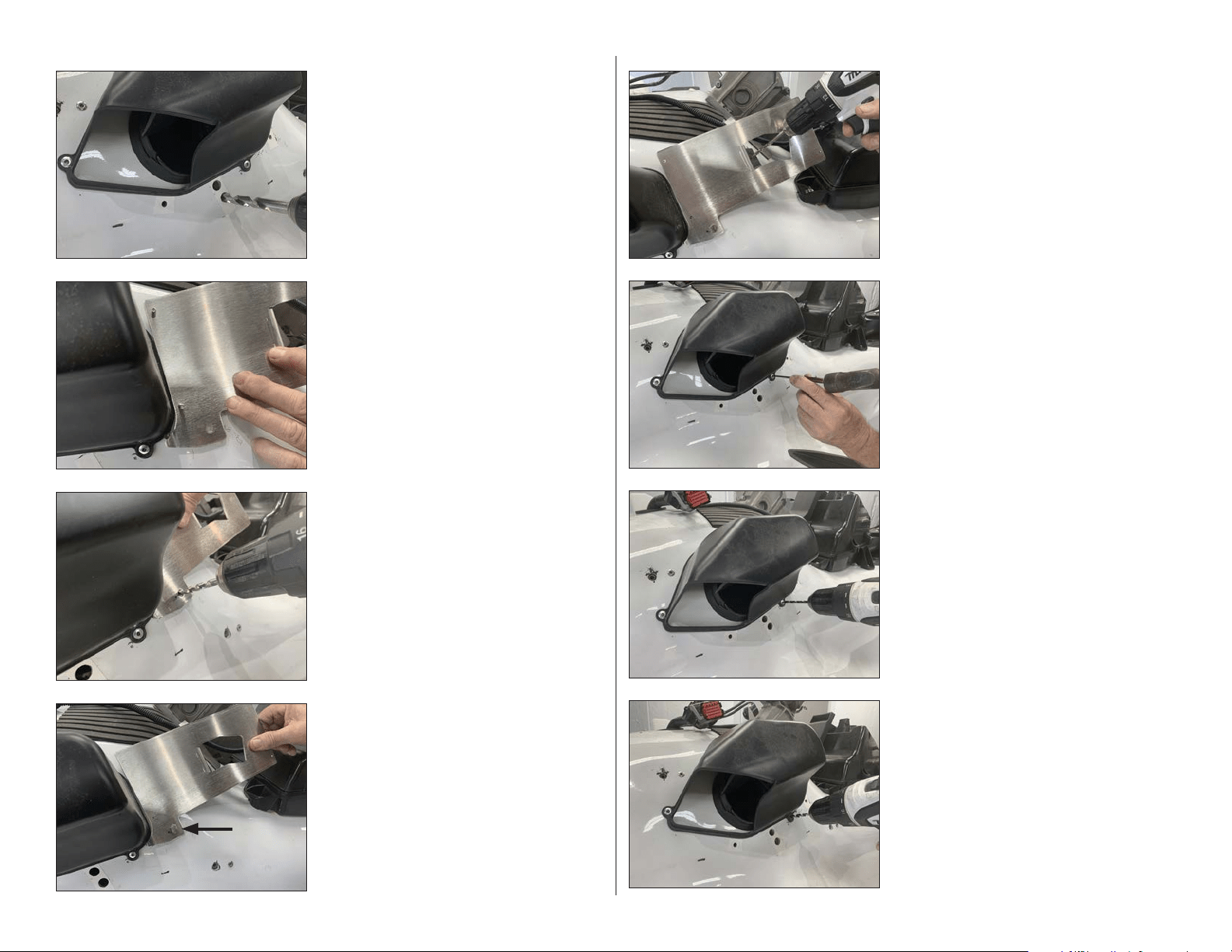
STEP 32
With the rivet removed, enlarge the hole in the
induction box mounting tab and the hull to
1/4”.
STEP 31
Using a 3/16” drill bit, carefully drill through the
rivet head and remove the rivet.
STEP 30
Use a center punch to tap in the center of the
lower rivet on the induction box on the port
side.
STEP 29
Ensure the Amplifier Bracket is aligned with
the induction box. Using a 1/4” drill bit and the
upper mounting hole on the Amplifier Bracket
as a guide, carefully drill through the hull.
Remove the 1/4 - 20 x 1” Hex Cap Screw and
the Amplifier Bracket from the vessel.
STEP 28
Slide a 1/4 - 20 x 1” Hex Cap Screw through the
lower mounting hole on the Amplifier Bracket,
into the hull.
STEP 27
Using a 1/4” drill bit and the lower mounting
hole on the Amplifier Bracket as a guide,
carefully drill through the hull.
STEP 26
Align the Amplifier Bracket to the back of the
induction box on the port side.
STEP 25
Enlarge the other two holes using a 7/16” drill
bit.
Repeat Steps 22-25 on the starboard side.
SLPK-YA-19FXC / SLPK-YA-19FXC-SUB INSTR_SKU# 011531
Page 8 • JL Audio, Inc., 2020 Continued on Next Page
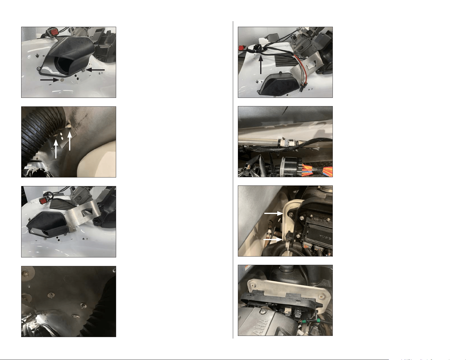
STEP 40
Pull the factory junction box panel off of the
firewall.
STEP 39
Remove the two bolts from the side of the
factory junction box panel. Repeat for the
opposite side.
STEP 38
Route the Power Harness down the inside of
the hull on the starboard side, toward the
battery. Use Cable Ties to secure the Power
Harness to the factory wiring.
STEP 37
Loosen the factory cable tie below the console
grommet on the hull, and pass the Power
Harness down through the grommet until
approximately 19” of the connector end remain
exposed above.
STEP 36
From inside the hull, secure the Amplifier
Bracket to the vessel using a 1/4” Oversized
Flat Washer and a 1/4 - 20 Nylon Insert Locknut
over each 1/4 - 20 x 1” Hex Cap Screw, and fully
tighten.
STEP 35
Align the Amplifier Bracket to the vessel. Slide
a 1/4” Flat Washer over each of two 1/4 - 20 x 1”
Hex Cap Screws. Apply Loctite® Threadlocker
to each, and pass an assembly through the
mounting holes in the Amplifier Bracket,
through the holes drilled in Steps 27 & 29.
STEP 34
From inside the hull, align the outer holes in a
Back Plate with the hardware installed in the
previous step. Ensure the curved side of the
Back Plate is oriented upward. Secure the Back
Plate using a 1/4” Oversized Flat Washer and a
1/4 - 20 Nylon Insert Locknut over each 1/4 - 20
x 1” Hex Cap Screw, and fully tighten.
Repeat Steps 30-34 on the starboard side.
STEP 33
Slide a 1/4” Flat Washer over each of two
1/4 - 20 x 1” Hex Cap Screws. Apply Loctite®
Threadlocker to each, and pass an assembly
through each of the indicated holes drilled in
Steps 24 & 32.
SLPK-YA-19FXC / SLPK-YA-19FXC-SUB INSTR_SKU# 011531
Page 9 • JL Audio, Inc., 2020 Continued on Next Page
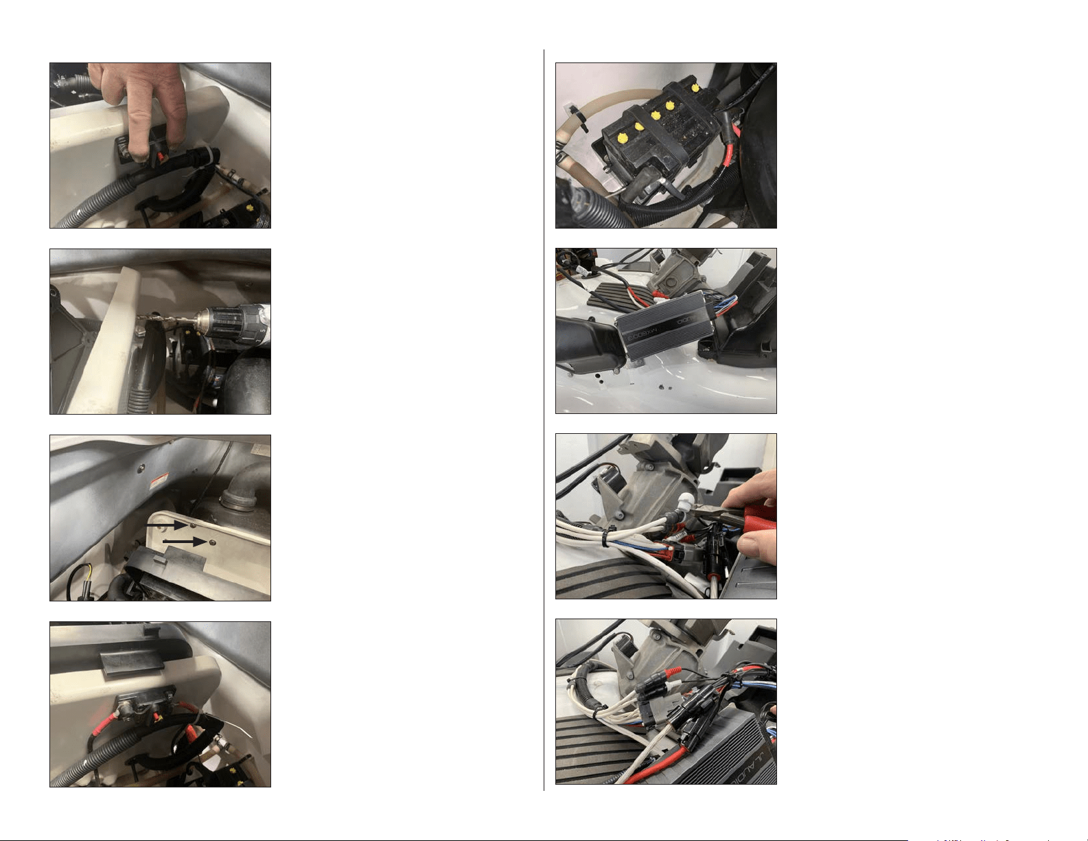
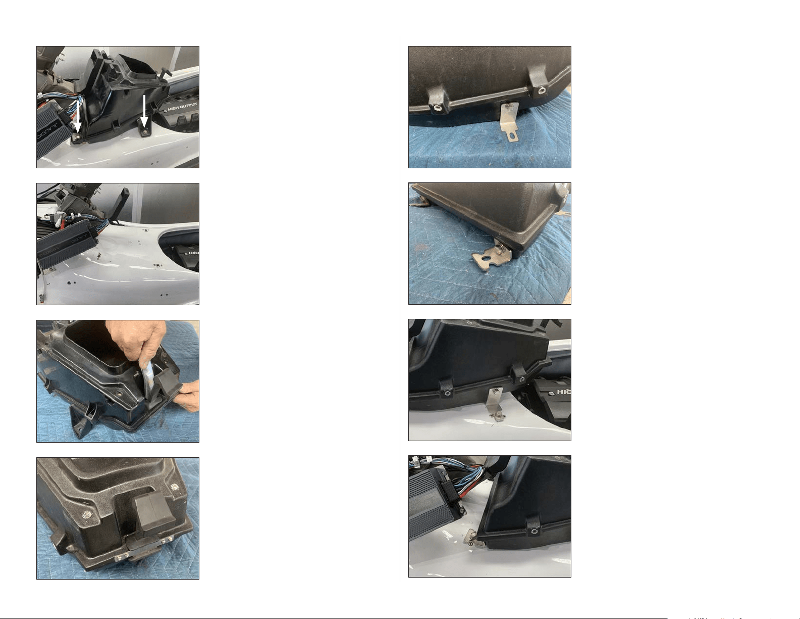
STEP 48
Connect the Power Harness to the Amplifier,
and secure with Cable Ties.
STEP 47
Connect the Amplifier Harness to the Amplifier.
Slide a piece of 2” Heat Shrink Tubing over each
channel of the RCA Interconnects, and
connect to the Front Input jacks of the
Amplifier Harness. Carefully cut the red and
white protective caps from the Front Input
jacks of the Amplifier Harness. Position the 2”
Heat Shrink Tubing over the joined
connections, and use a heat gun or torch to
shrink the tubing.
STEP 46
Align the Amplifier over the studs on the
Amplifier Bracket with the wiring exiting the
Amplifier toward the rear.
Secure the Amplifier to the Amplifier Bracket
using three 8-32 Washers and 8-32 Locknuts,
and fully tighten.
STEP 45
Connect the opposite end of the 8 AWG Power
Cable Extension to the positive battery
terminal and connect the ground cable from
the Power Harness to the negative battery
terminal. Secure cables with Cable Ties.
STEP 44
Press the red button on the Circuit Breaker to
disengage it.
Connect the positive power cable to one side
of the Circuit Breaker and the 8 AWG Power
Cable Extension to the other side.
STEP 43
Slide a 1/4” Flat Washer over each of two 1/4 -
20 x 1” Hex Cap Screws, and pass an assembly
through each of the mounting holes in the
Circuit Breaker, through the holes drilled in the
previous step. Secure the Circuit Breaker to the
fire wall using a pair of 1/4” Flat Washers and
1/4 - 20 Nylon Insert Locknuts on the front side
of the fire wall, and fully tighten.
Reinstall the factory junction box panel.
STEP 42
Using a 1/4” drill bit, carefully drill through each
of the marks made in the previous step.
STEP 41
Align the Circuit Breaker along the upper edge
of the back side of the fire wall. Using the
Circuit Breaker as a template, mark the
locations of the mounting holes.
SLPK-YA-19FXC / SLPK-YA-19FXC-SUB INSTR_SKU# 011531
Page 10 • JL Audio, Inc., 2020 Continued on Next Page
STEP 56
Align the lower slots in the Short Brackets with
the factory holes in the hull.
Thread the factory bolts removed in Step 49
through the slots in the Short Brackets, into the
factory inserts, and hand tighten.
STEP 55
Place the subwoofer enclosure onto the vessel.
Align the lower slots in the Long Brackets with
the factory holes in the hull.
Thread the factory bolts removed in Step 49
through the slots in the Long Brackets, into the
factory inserts, and hand tighten.
STEP 54
Align the short end of a Short Bracket to a
threaded insert on the lower front of the sub-
woofer enclosure.
Pass a 1/4” Flat Washer over a 1/4 - 20 x 1”
Hex Cap Screw. Apply Loctite® Threadlocker,
thread the assembly through the slot in the
Short Bracket, into the threaded insert in the
subwoofer enclosure, and hand tighten. Repeat
the process for the opposite side.
STEP 53
Align the wide end of a Long Bracket to a
threaded insert on the lower side of the
subwoofer enclosure.
Pass a 1/4” Flat Washer over a 1/4 - 20 x 1”
Hex Cap Screw. Apply Loctite® Threadlocker,
thread the assembly through the slot in the
Long Bracket, into the threaded insert in the
subwoofer enclosure, and hand tighten. Repeat
the process for the opposite side.
STEP 52
Remove the four #6 x 1/2” Pan Head Screws
and Latch Bracket from the subwoofer
enclosure. Slide the latch into the recess at
the rear of the subwoofer enclosure. Apply
Loctite® Threadlocker to the four #6 x 1/2” Pan
Head Screws, and reinstall the Latch Bracket,
ensuring the center tab is oriented downward.
Secure the Latch Bracket to the subwoofer
enclosure, and fully tighten.
STEP 51
Carefully pry the rubber latch from the center
storage compartment.
STEP 50
Remove the center storage compartment from
the vessel.
STEP 49
NOTE: Steps 49-56 are used for the
installation of the subwoofer (SLPK-YA-
19FXC-SUB, sold separately). For
installations without a subwoofer, skip
ahead to Step 57.
Remove the two indicated screws from each
side of the center storage compartment.
SLPK-YA-19FXC / SLPK-YA-19FXC-SUB INSTR_SKU# 011531
Page 11 • JL Audio, Inc., 2020 Continued on Next Page
STEP 64
Using a 1/8” drill bit, carefully drill a pilot hole
through the mark on Template C and through
the body panel.
STEP 63
Carefully cut Template C from the clear sheet
on the indicated line.
Align Template C with the back of the port side
body panel, and tape it into position.
STEP 62
Reinstall the two factory screws removed in
Step 11 back into the front of the console.
If a subwoofer was installed, fully tighten the
hardware installed in Steps 53-56.
Remove the four factory screws installed in
Step 61.
STEP 61
Reinstall the console, and reconnect the main
harness and the Menu Scroll / Alarm Mute
switch.
Align the four holes on the top of the console
with the four threaded inserts on the top of the
subwoofer enclosure or center storage pocket.
Temporarily reinstall the four factory screws
removed in Step 10.
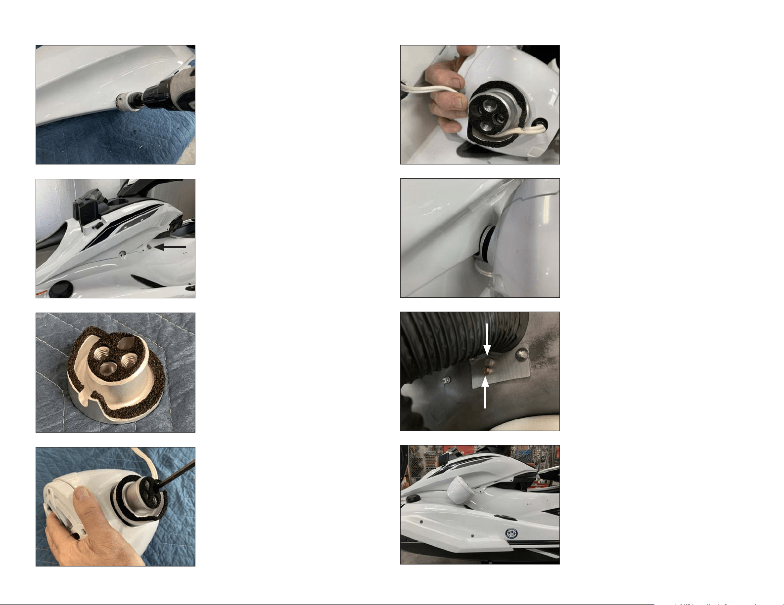
STEP 60
Add the thick round gasket to the MBT-CRXv2
controller, aligning the small hole in the gasket
with the alignment pin on the back of the
controller, and guide the controller’s wiring
through the hole drilled in the previous step.
From the underside, add the thin round gasket,
then secure the MBT-CRXv2 using the threaded
fastening collar. Reference the illustration in
the MBT-CRXv2 owner’s manual for details.
STEP 59
Using a 1-1/8” hole saw, enlarge the pilot hole
drilled in the previous step.
STEP 58
Using a 1/8” drill bit, carefully drill a pilot hole
through the mark on Template B and into the
hull.
Remove Template B from the vessel.
STEP 57
Carefully cut Template B from the clear sheet
on the indicated line.
Align Template B with the top of the console,
and tape it into position.
SLPK-YA-19FXC / SLPK-YA-19FXC-SUB INSTR_SKU# 011531
Page 12 • JL Audio, Inc., 2020 Continued on Next Page
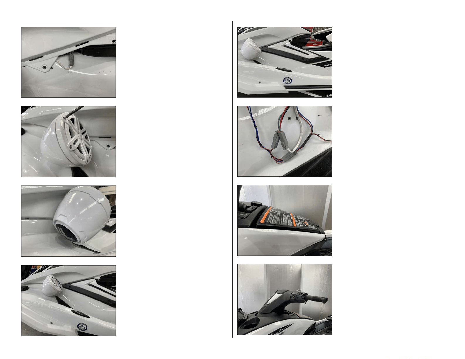
STEP 72
Pictured is a VEX Speaker Enclosure installed
on the port side in the proper orientation.
STEP 71
Slide a 7/16” Split Lock Washer over each of two
7/16 - 14 x 7/8” Hex Head Bolts. Apply Loctite®
Threadlocker to each assembly, and secure the
VEX Speaker Enclosure to the vessel through
the holes in the Back Plate from inside the hull,
and fully tighten.
STEP 70
Align the Port VEX Adaptor with hole cut in the
body panel in Step 65.
STEP 69
Route the speaker cable exiting the VEX
Speaker Enclosure around the channel in the
Port VEX Adaptor, then pass the cable under
the body panel and toward the rear of the
panel.
STEP 68
Align the Port VEX Adaptor to the top of a
VEX Speaker Enclosure, with the notch on the
Port VEX Adaptor oriented to the rear. Apply
Loctite® Threadlocker to a pair of M6 - 1 x
20mm Socket Cap Screws, secure the Port VEX
Adaptor to the VEX Speaker Enclosure, and
fully tighten.
STEP 67
Apply the Port VEX Adaptor Gasket to the back
of the Port VEX Adaptor.
STEP 66
Reinstall the body panel. Reinstall the two
factory screws in the top of the console and
the two screws removed in Step 7.
Ensure the left speaker connector from the
Amplifier Harness is accessible at the rear of
the panel.
STEP 65
Turn the body panel over. Using a 1-7/8” hole
saw, carefully enlarge the pilot hole.
SLPK-YA-19FXC / SLPK-YA-19FXC-SUB INSTR_SKU# 011531
Page 13 • JL Audio, Inc., 2020 Continued on Next Page
STEP 80
Reinstall the handle bar to the factory torque
specification.
Reinstall the throttle control and steering
column cover panel, then reinstall the lower
and upper handle bar cover panels.
STEP 79
Reinstall the center storage compartment lid.
STEP 78
Connect the MBT-CRXv2 wiring and sub
connector, if applicable, to the Amplifier Harness.
Slide a piece of 2” Heat Shrink Tubing over each of
the RCA Interconnects, and connect to the MBT-
CRXv2. Position the 2” Heat Shrink Tubing over the
joined connections and shrink using a heat gun or
torch. Secure wiring with Cable Ties.
NOTE: The remaining red and black wires are provided
for use with optional Yamaha accessories. Apply 1”
Heat Shrink Tubing to any connections or if left unused.
STEP 77
Reinstall the three accent panel screws
removed in Step 8.
Repeat Steps 63-77 for the starboard side.
STEP 76
Reinstall the accent panel on the port side.
STEP 75
Remove the adhesive backing from the Rear
Logo Appliqué. With the logo positioned at the
desired angle, attach the Rear Logo Appliqué,
gently pressing on the center to remove any air
pockets.
STEP 74
Remove the six #8 x 1-1/4” Pan Head Screws
and #8 Flat Washers, rotate the speaker to the
desired angle, and reinstall.
STEP 73
Connect the speaker cable from VEX Speaker
Enclosure to the left speaker connector from
the Amplifier Harness.
Reinstall the remaining two screws at the front
of the body panel
SLPK-YA-19FXC / SLPK-YA-19FXC-SUB INSTR_SKU# 011531

Page 14 • JL Audio, Inc., 2020
CONGRATULATIONS!
You have completed the installation for this model! Enjoy your new SlamPak™!
STEP 83
Press in on the yellow arm of the Circuit
Breaker to engage it.
STEP 82
Reinstall the lower access panel.
STEP 81
Reinstall the upper access panel.
SPECIFICATIONS
SPEAKERS
Continuous Power Handling (RMS): 60 watts / channel
Nominal Impedance: 4 ohms
Frequency Response: 100 Hz - 25 kHz +/- 3 dB
SUBWOOFER
Continuous Power Handling: 200 watts
Nominal Impedance: 4 ohms
POWER OUTLET
Voltage: 12 volts
Maximum Capacity: 10 amps
Nominal Impedance: 4 ohms
All specifications are subject to change without notice. “JL Audio®” and “How we play®” are registered trademarks of JL Audio, Inc. “Ahead of the Curve” and its respective logo are trademarks
of JL Audio, Inc.
Printed in USA • ©2020 JL Audio, Inc. • For more detailed information please visit us online at www.jlaudio.com.
(954) 443-1100
www.jlaudio.com
JLA-SKU# 011531 • ver. 07.15.2020 • 10369 NORTH COMMERCE PARKWAY • MIRAMAR, FLORIDA • 33025 • USA
®
SLPK-YA-19FXC / SLPK-YA-19FXC-SUB INSTR_SKU# 011531
STEP 84
Reinstall the under seat locker and both seat
sections.
Refer to the MBT-CRXv2 owner’s manual to pair
your mobile device.
*011531*