
Enclosure Installation Manual

| Fathom IWSPage 2
NOTES
Page 3 | Fathom IWS
IMPORTANT SAFETY INSTRUCTIONS
1) Read the Instructions — All safety and operating instructions should be
read before the subwoofer is operated.
2) Retain the Instructions — ese instructions should be retained
for future reference.
3) Heed Warnings — All warnings in these instructions should be followed.
4) Water and Moisture — e enclosure and subwoofer should NOT be used
near water – for example, near a bathtub, washbowl, sink, laundry tub, in a
wet basement, near a swimming pool, etc.
5) Heat and Flames — e enclosure and subwoofer should be situated away
from heat sources such as radiators, heat registers, stoves, replaces, or other
devices which produce heat. Do not place candles nearby.
6) Object or Liquid Entry — Care should be taken so that objects do not fall
into and liquids are not spilled onto the enclosure, subwoofer or grille. Do not
expose to dripping or splashing from liquids. Do not place objects lled with
liquids nearby. For example: ower vases, beverages, liquid-fueled lamps, etc.
7) Damage Requiring Service — e subwoofer should be serviced by qualied
service personnel when:
a. objects have fallen or liquid has been spilled into the subwoofer
b. the subwoofer has been exposed to rain
c. the subwoofer does not appear to operate normally or exhibits a marked
change in performance
d. the subwoofer driver’s cone and/or suspension has been
physically damaged
WARNING
THIS SUBWOOFER IS CAPABLE OF PRODUCING VERY HIGH SOUND
PRESSURE LEVELS. PLEASE EXERCISE RESTRAINT IN ITS OPERATION TO
PROTECT YOUR HEARING FROM PERMANENT DAMAGE.

| Fathom IWSPage 4
TABLE OF CONTENTS
Important Safety Instructions: ......................................... 2-3
Introduction and Overview: ............................................. 4
System Components: ................................................. 5-7
Installation Hardware / Tools for Installation: ............................. 8
What’s In e Box?: .................................................... 9
Enclosure Installation Procedure: .................................... 10-17
Limited Warranty / Service Information: ................................. 19
Specications: ........................................................ 20
INTRODUCTION
ank you for choosing the JL Audio Fathom In-Wall Subwoofer System, also
known as the IWS.
is document contains detailed instructions for the installation of the Fathom
IWS enclosure. Since a portion of the enclosure will be inaccessible aer installation,
we strongly recommend reading these instructions completely before beginning the
installation process. Please note, these instructions are for the installation of one (1)
IWS enclosure. Simply repeat the steps to install additional enclosures.
FATHOM IWS SYSTEM OVERVIEW
e Fathom IWS is oered in two options:
- System One includes all elements for the installation of one (1) subwoofer.
- System Two includes all elements for the installation of two (2) subwoofers.
Each Fathom IWS System consists of four elements:
System One System Two
(1) Enclosure (2) Enclosures
(1) Subwoofer (2) Subwoofers
(1) Grille Assembly (2) Grille Assemblies
(1) 1kW Amplier (1) 2kW Amplier
Each system includes specialized hardware to ensure proper installation.
Page 5 | Fathom IWS
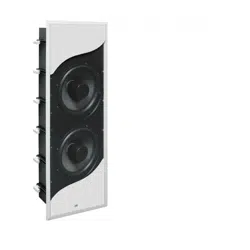
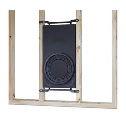
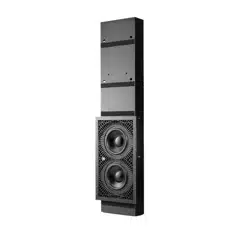
THE ENCLOSURE
e Fathom IWS enclosure is designed to suspend from a single anchor
point inside the wall cavity of 16-inch, on-center stud (aluminum or wood)
construction homes. Once installed, the enclosure will “hang” snugly within
the wall cavity. e enclosure has various spacers and padding applied to
specic areas, allowing it to only make gentle contact with its surrounding
wallboard surfaces. e placement and amount of pressure applied by these
pads is a critical design aspect to ensure proper t and should not be altered
in any way. Failure to use the proper enclosure and/or alteration of the spacers
and padding will result in loss of performance and unwanted wall vibrations.
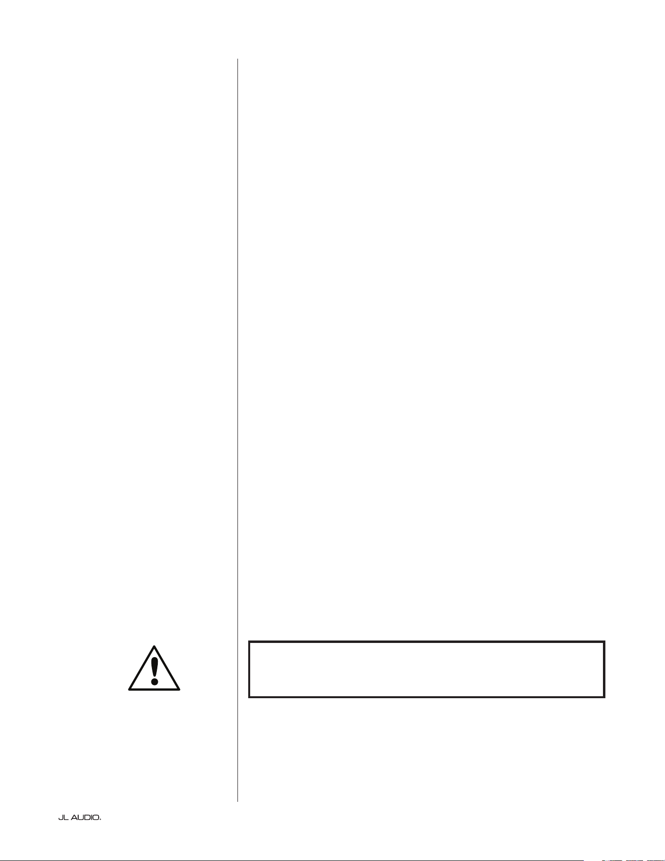
e Fathom IWS uses two enclosure types, referred to as the “A” box
and the “B” box. e “A” box is designed for 2 x 4 stud construction,
and the “B” box is designed for 2 x 6 stud construction.
Enclosure Type Enclosure Dimensions*
“A” Box
70-inches x 13.75-inches x 2.9-inches
(1778 mm x 349 mm x 74 mm)
“B” Box
55-inches x 13.75-inches x 4.7-inches
(1397 mm x 349 mm x 119 mm)
*Dimensions listed are approximate and do not include various spacers and padding.
Furthermore, depending on the actual stud dimensions, there are variations
available for each enclosure type. We strongly recommend measuring your actual
stud dimensions to verify you have the correct enclosure for your application (see
chart below).
“A” Box Enclosure Variations for 2 x 4 Stud Construction
Actual Stud Width Enclosure Model SKU
3 1/2-inches (89 mm) IWEv2-113A-3.50 96093
3 5/8-inches (92 mm) IWEv2-113A-3.63 96094
4-inches (102 mm) IWEv2-113A-4.00 96095
“B” Box Enclosure Variations for 2 x 4 Stud Construction
Actual Stud Width Enclosure Model SKU
5 1/2-inches (140 mm) IWEv2-113B-5.50 96096
6-inches (152 mm) IW Ev2-113B - 6. 0 0 96097
“A” Box “B” Box
Spacers and
padding will vary to
ensure a proper t.
| Fathom IWSPage 6
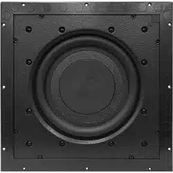
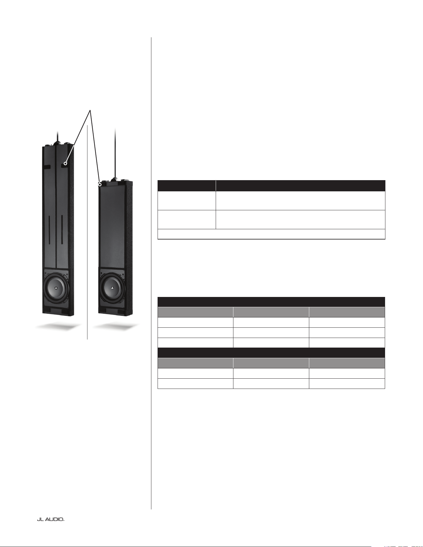
THE SUBWOOFER
Derived from JL Audio’s revolutionary TW5 design platform, the subwoofer
used in the Fathom IWS employs our patented thin-line woofer technology
to achieve extreme excursion capability and ultra-low frequency extension.
To reduce the possibility of damage during home construction or during the
enclosure’s installation process, the subwoofer is not pre-installed. e subwoofer
should only be installed aer all aspects of construction and wall nishing have
been completed.
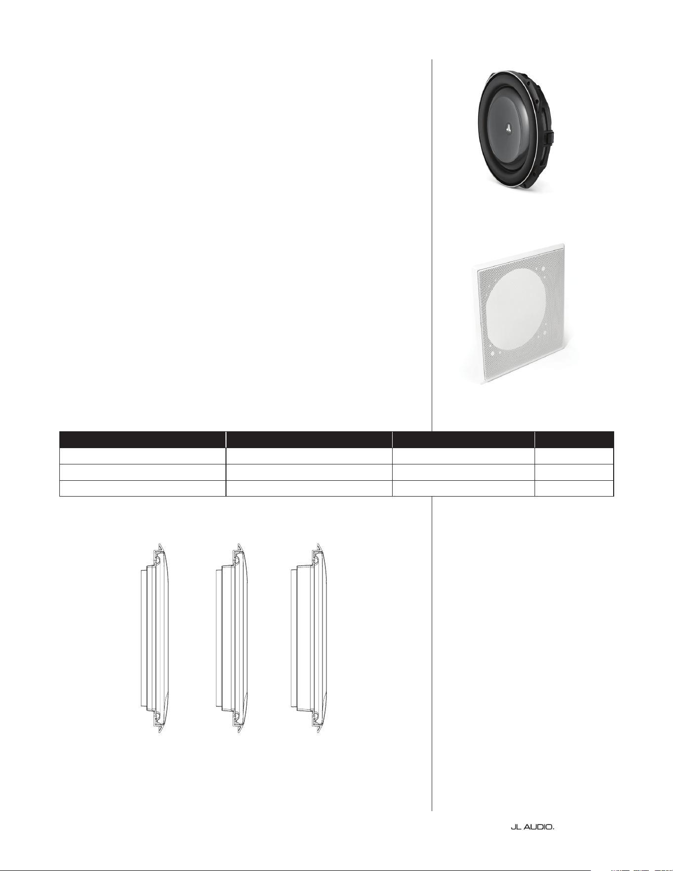
THE GRILLE ASSEMBLY
e Fathom IWS enclosure uses a grille that mounts directly to the wall studs
instead of the enclosure. e grille assembly consists of a removable outer metal
mesh and grille tray unit. e grille’s design allows the enclosure to attach to the
wall without making actual hard contact with the enclosure itself.
is unique mounting method allows the enclosure to essentially “oat”
within the wall cavity without transferring vibrations to the wall itself. A plastic
paint guard is included to protect the woofer from overspray during painting. e
outer metal mesh and grille frame should be painted separately to prevent them
from sticking together.
e grille assembly is available in three size range options to accommodate
nine dierent wallboard thicknesses. It is critical to use the correct grille size
for proper t. Refer to the chart below to verify that your grille assembly is
compatible with the wallboard thickness used in your application. Do not
attempt to use or modify a grille that does not t your application.
Wallboard Thickness (inches) Wallboard Thickness (mm) Grille Assembly Model SKU
1/2” to less than 13/16” 12.7 mm to less than 20.6 mm IWG -113-X 96090
13/16” to less than 1 3/16” 20.6 mm to less than 30.2 mm IWG -113-Y 96091
1 3/16” to less than 1 9/16” 30.2 mm to less than 39.7 mm IWG -113 -Z 96092
Note: The grille models listed on this page are only compatible
with the v2 Enclosures listed on page 5.
X Y Z
Page 7 | Fathom IWS
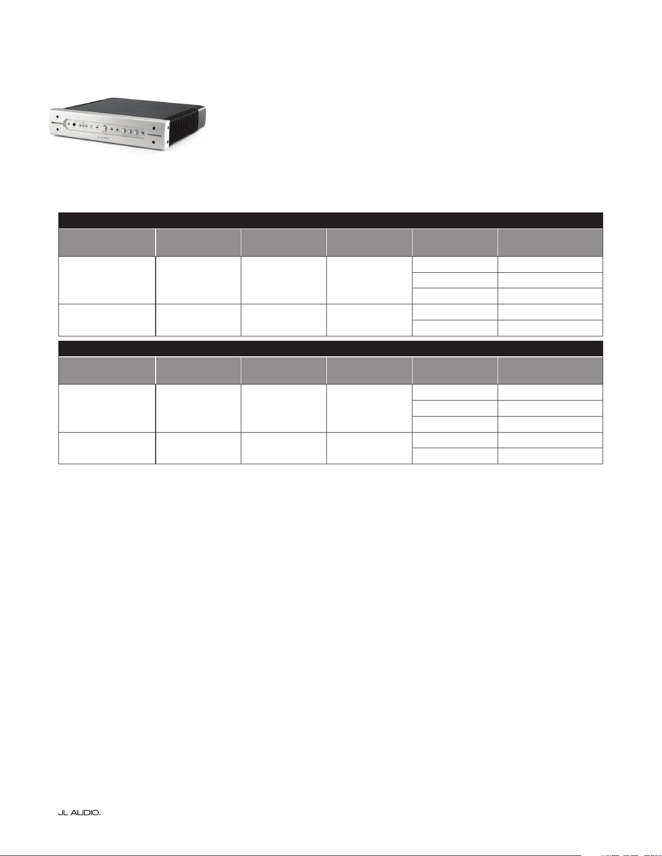
THE AMPLIFIER
e Fathom IWS uses a unique amplier, specically engineered to
take full advantage of the Fathom IWS subwoofer’s full excursion envelope.
ere are two amplier models, a 1kW amplier for the System One
and a 2kW version for the System Two. Both are available as either 120V
or 240V AC powered. Besides their output and AC power distinctions,
both ampliers incorporate specic equalization curves for use with
each particular enclosure type (“A” or “B” box). Refer to the charts below
to verify that you have the correct amplier for your application.
System One: 1kW Amplier
Amplier Model
Amplier SKU
120V / 60Hz
Amplier SKU
240V / 50Hz
Enclosure Type Enclosure SKU Actual Stud Width
SA-1KW-IWS113Ax1 96070 96270 “A” Box
96093 3 1/2-inches (89 mm)
96094 3 5/8-inches (92 mm)
96095 4-inches (102 mm)
SA-1KW-IWS113Bx1 96071 96271 “B” Box
96096 5 1/2-inches (140 mm)
96097 6-inches (152 mm)
System Two: 2kW Amplier
Amplier Model
Amplier SKU
120V / 60Hz
Amplier SKU
240V / 50Hz
Enclosure Type Enclosure SKU Actual Stud Width
SA-2KW-IWS113Ax2 96072 96272 “A” Box
96093 3 1/2-inches (89 mm)
96094 3 5/8-inches (92 mm)
96095 4-inches (102 mm)
SA-2KW-IWS113Bx2 96073 96273 “B” Box
96096 5 1/2-inches (140 mm)
96097 6-inches (152 mm)

| Fathom IWSPage 8
INSTALLATION HARDWARE
e System One enclosure package includes all parts and hardware
necessary for the installation of one (1) enclosure. e System Two
enclosure package includes all parts and hardware to complete the
installation of two (2) enclosures. Please verify that you have all
the required items below before beginning the installation.
Item / Description
Qty Included With
System One
Qty Included With
System Two
IWS enclosure with pre-attached wallboard template 1 2
“Go” gauge, measuring 14 3/8-inches wide (365.1 mm) 1 2
Mounting bracket assembly (with centering template) 1 2
Hanging rod (11.25-inches for “A” box or 26.25-inches for “B” box) 1 2
#8, 1.25-inch wafer head screws 50 100
Wire/cable ties 3 6
Energy absorbing foam gasket strip 50 foot length 100 foot length
TOOLS FOR INSTALLATION
Below is a list of tools necessary to perform the installation of the Fathom
IWS enclosure. Depending on the specics of your installation, you may need
additional tools, hardware and/or accessories. Enrolling a friend or coworker to
assist in liing the enclosure will be helpful.
• Safety glasses • Tape measure (100-inch minimum)
• Cordless drill/driver with #2 Phillips bit • Drill bits
• Pliers • Wire strippers
• Wire cutters • Utility knife or scissors
• Permanent marker • Drop cloth (optional)
• Masking tape (optional)
Page 9 | Fathom IWS
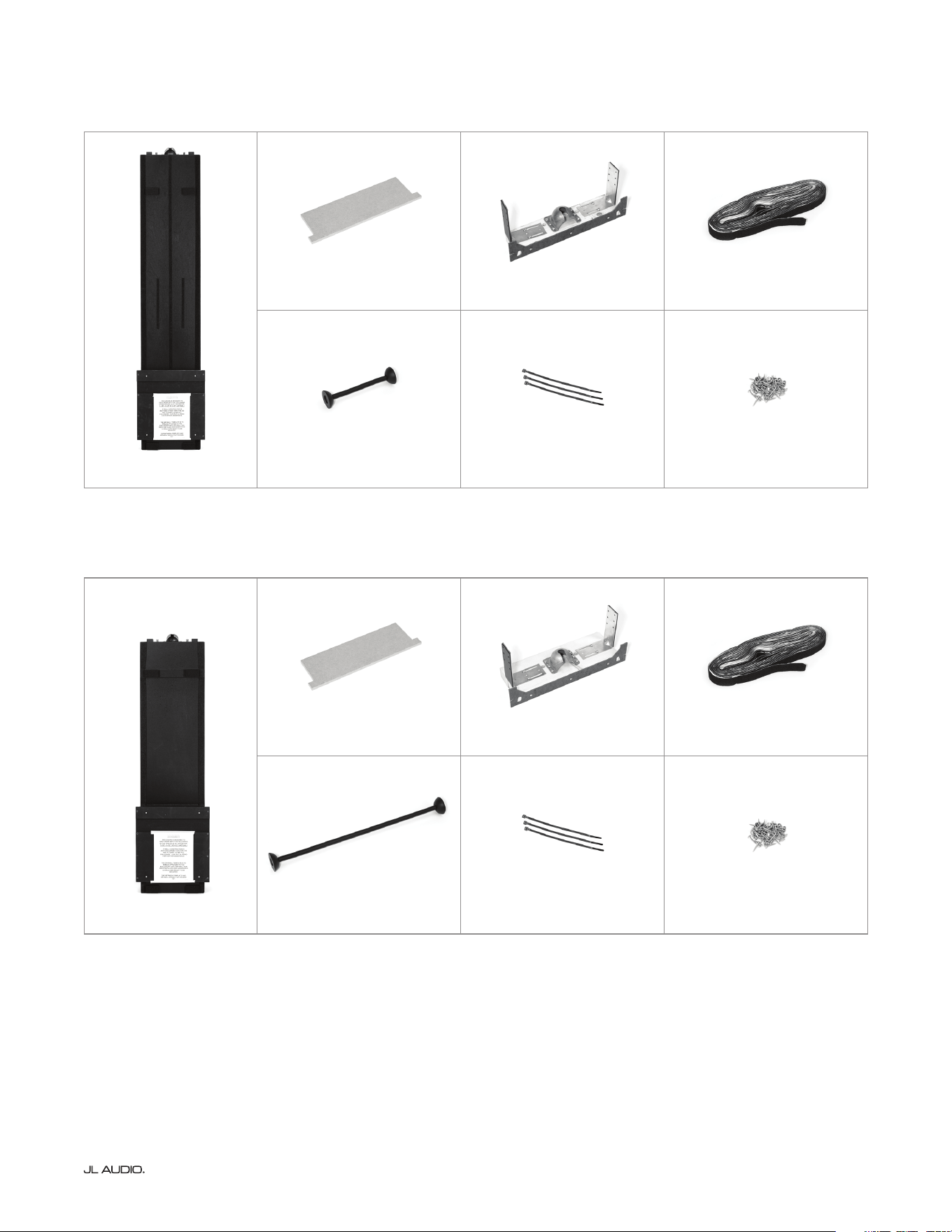
WHAT’S IN THE BOX? THE “A” BOX
WHAT’S IN THE BOX? THE “B” BOX
Enclosure (x1)
“Go” Gauge (x1) Mounting Bracket (x1) Foam Gasket (x1)
Hanging Rod (x1) Cable Ties (3) Pack of Screws (x1)
Enclosure (x1)
“Go” Gauge (x1) Mounting Bracket (x1) Foam Gasket (x1)
Hanging Rod (x1) Cable Ties (3) Pack of Screws (x1)
| Fathom IWSPage 10
ENCLOSURE INSTALLATION PROCEDURE
Prepping the Work Area
Fathom IWS enclosures may be installed in both new and pre-existing
construction homes. When working with pre-existing construction, you will
need to open a stud bay and expose the studs on either side of the opening. For
pre-existing construction installations, we recommend using masking tape and
a drop cloth to protect the home’s interior from construction debris. For your
safety, make sure there are no live electrical circuits/conduits within the stud
bay prior to beginning the installation.
Evaluating the Wall Cavity
Inspect the stud bay to ensure that you have at least 93 5/8-inches (93.625
in/2.38 m) of unobstructed height inside the wall cavity (measurement should
be taken from an unnished oor). e IWS enclosure is designed to hang freely
or “oat” within the wall cavity, so anything coming into contact with it can
lead to unwanted vibrations and rattles that cannot be accessed/corrected aer
the installation. e width inside the studs, over the entire 93 5/8-inches (93.625
in/2.38 m), must be no less than 14 3/8-inches (14.375 in/365.1 mm) and no
greater than 14 7/8-inches (14.875 in/377.8 mm). e studs on either side of the
wall cavity must be straight, plumb and parallel, without any twisting or bowing.
If your stud bay has any obstructions (wiring, conduits, cross-members, etc.),
you’ll need to work with your general contractor to discuss removing/relocating
them, or you will need to choose a dierent stud bay.
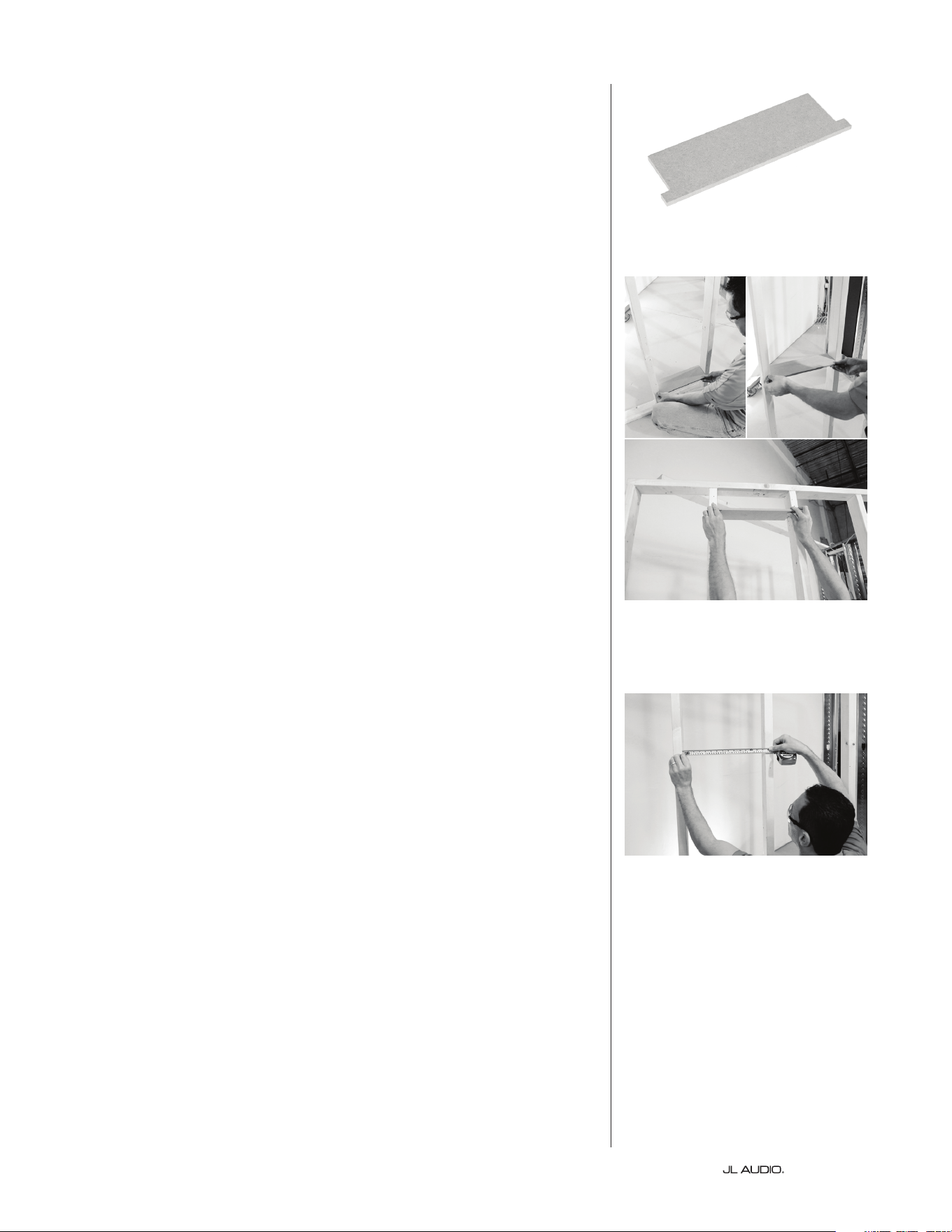
A “Go” gauge is provided to ensure that the minimum required width of 14
3/8-inches (14.375 in/365.1 mm) is maintained throughout the entire height of
the wall cavity. To use, insert the “Go” gauge into the bottom of the wall cavity
and slowly raise it to the top, keeping it level and parallel with the oor. If at any
point the gauge binds or does not t, you’ll need to consult with your general
contractor to safely modify or move the studs to allow for proper clearance.
Next, use a tape measure to verify that the maximum width between the studs
does not exceed 14 7/8-inches (14.875 in/377.8 mm). Here again, if the width is
too great at any point, consult with your general contractor to safely modify or
move the studs. is is vital since the IWS grille assembly is designed to attach
directly to the wall studs.
“Go” Gauge
Use the “Go” gauge to verify that the
minimum width of 14 3/8-inches is
maintained over entire wall cavity height.
Use a tape measure to verify that the
maximum width of 14 7/8-inches over
entire wall cavity height is not exceeded.
Page 11 | Fathom IWS
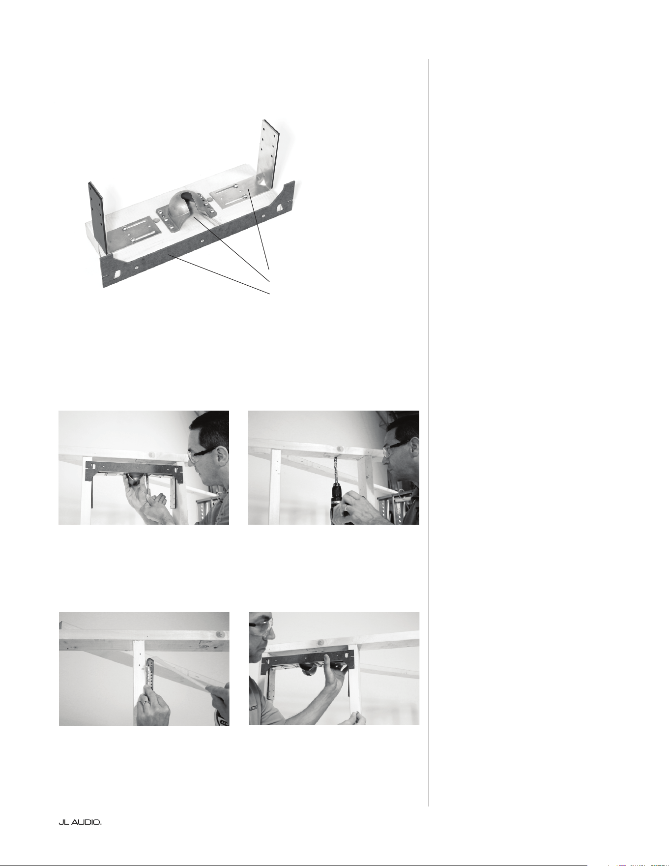
Installing the Mounting
Bracket Assembly
e Fathom IWS enclosure
mounting bracket assembly is
designed for installation between
the two studs at a specic height.
e bracket assembly includes two
steel L-brackets that are attached via
slotted openings. e screws in the
slotted openings are not fastened all
the way, permitting the L-brackets to
slide horizontally. is will allow the
mounting bracket to be easily adjusted
and centered between the two studs.
At this point, we suggest you
consider your speaker cable’s routing
path before installing the mounting
bracket assembly, as these areas
may be dicult to access once the
mounting bracket is in place.
• To route the speaker cable
through an above wall header: Using
the mounting bracket as a guide,
insert a permanent marker through
one of the predrilled holes in the
wooden cross-member and mark the
wall header above to drill a hole for
routing your speaker cable into the
wall cavity. (Figure 1 & 2)
• To route the speaker cable
through either adjacent stud bay:
With the mounting bracket installed
(see following steps), drill a hole
(below either steel L-bracket) into
an adjacent stud bay to route your
speaker cable. Please note, when
working with metal studs, make sure
any drilled holes are clear of burrs
and sharp edges.
Measure up from an unnished
oor and mark both stud faces at 90
1/2-inches (90.5 in/2.3 m) with a
permanent marker. (Figure 3) Position
the mounting bracket assembly in
the stud bay so that the bottom le
and right edges of the centering
template are level and line up with
the marks on the stud faces. (Figure
4)
Next, partially screw two of the #8
x 1.25-inch screws into the centering
template’s slotted openings. Make sure
Mounting Bracket Assembly
Steel L-brackets
Socket
Centering Template
Figure 1 Figure 2
Figure 3
Mark both stud faces at 90 1/2-inches
up from an unnished oor.
Figure 4
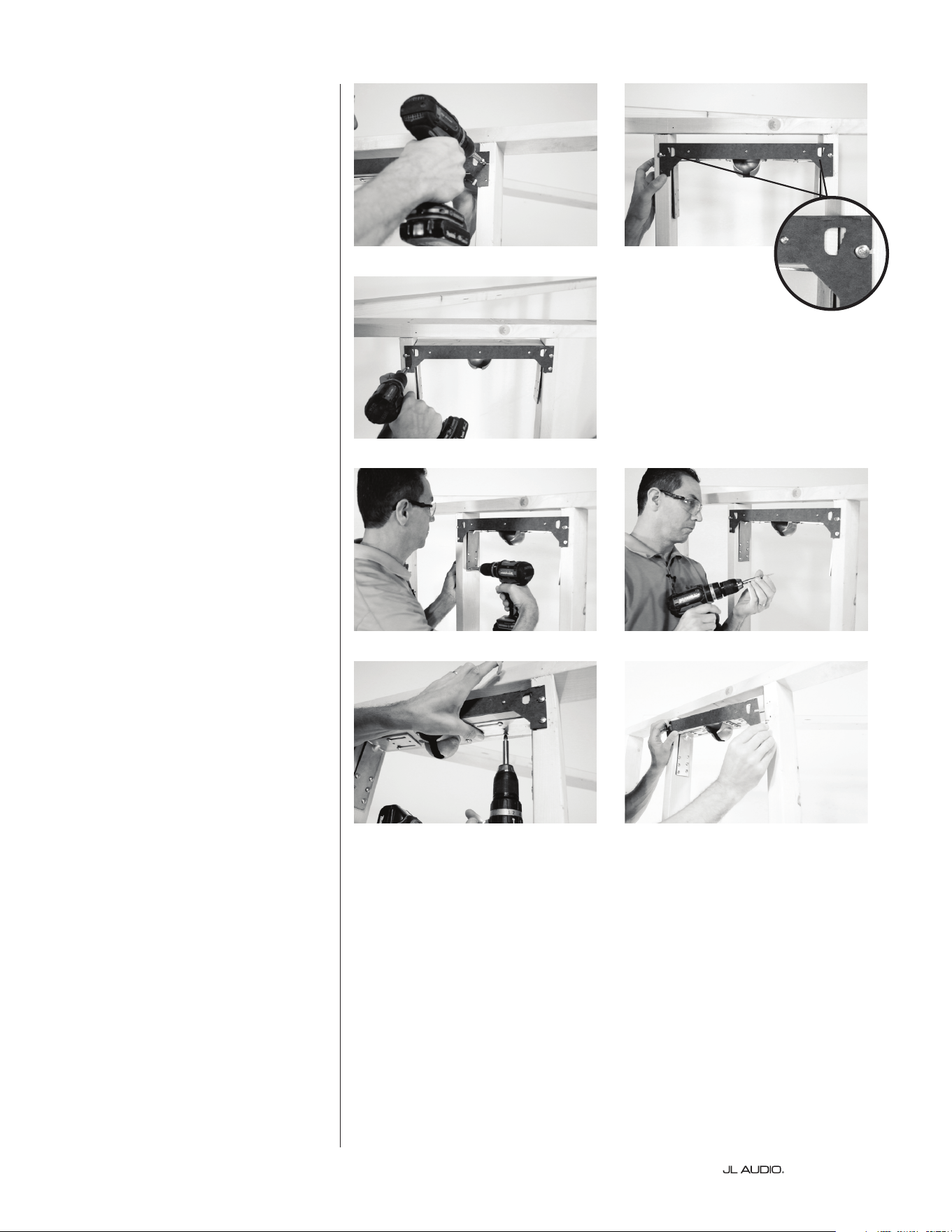
| Fathom IWSPage 12
to position each screw near the center
of each slotted opening, (Figure 5) as
the bracket needs to be able to shi
le to right within the stud bay.
e centering template has two
stepped window openings (Figure
6)
that allow you to visually center
the mounting bracket within the
wall cavity, without taking tedious
measurements. Viewing the stepped
windows as a guide, center the
mounting bracket assembly between
the inside edges of the le and right
wall studs. Once you have the same
position in both stepped windows,
tighten the two screws in the slotted
openings completely and install the
two remaining screws below to hold in
place. (Figure 7)
With the mounting bracket
centered, slide each steel L-bracket
until the foam padding is rmly
pressed against the inside of each
stud, and secure in place using six #8
x 1.25-inch screws in each L-bracket.
(Figures 8 & 9) Lock the mounting
bracket in place by tightening the two
pre-attached screws in the slotted
holes of each L-bracket. (Figure 10) Do
not install the remaining two screws
in each L-bracket at this time.
Once the mounting bracket is
rmly in place, remove the seven
screws along the front of the centering
template. (Figure 11) e template is no
longer needed.
Figure 5 Figure 6
Stepped Windows
for Centering
Figure 7
Figure 8 Figure 9
Figure 10
Figure 11

Page 13 | Fathom IWS
Applying the Foam Strips
e energy absorbing adhesive
foam gasket strip is used to avoid
potential vibrations, rattles and
buzzing between the studs and
wallboard, especially in installations
with metal stud construction.
Remove the backing and rmly
press the foam gasket strip to all
faces within the cavity (mounting
bracket and stud faces). Use a utility
knife or scissors to cut/trim the
edges of the foam gasket strip.
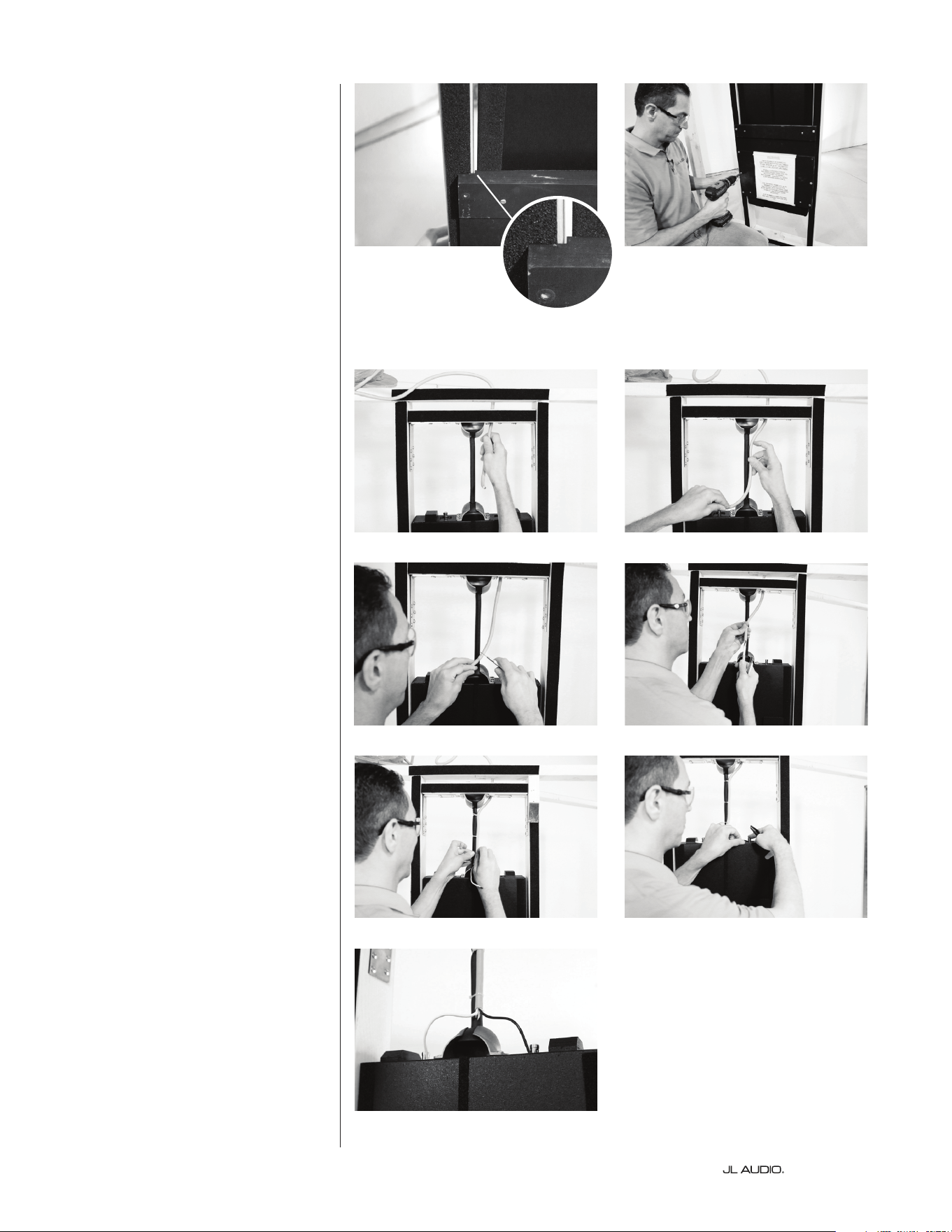
Hanging the Enclosure
With the mounting bracket
securely in place, insert one end of
the hanging rod into the enclosure’s
socket (Figure 12) and, with the help of
another person, li the enclosure into
the stud bay and place the other end
of the hanging rod into the mounting
bracket’s socket. (Figure 13)
Inspect the space clearances
between the enclosure’s sides and the
studs. e gap along the entire length
of the enclosure should be equal on
both sides. If the gaps are uneven,
this means the enclosure is hanging
o-center and the mounting bracket
needs to be adjusted. Loosen the
two slotted hole screws in each steel
L-bracket and slide the wooden cross-
member to the le or right until the
enclosure is visually centered in the
wall cavity.
Once centered, retighten
the two slotted hole screws and
install two more #8 x 1.25-inch
screws in the locking positions
in between the slotted holes of
each L-bracket. (Figure 14)
Once in place, the enclosure should
oat freely within the wall cavity
without making any hard contact.
(Figure 15)
Ax foam gasket strip to all stud
and mounting bracket faces.
Figure 12 Figure 13
Figure 14 Figure 15
Foam gasket strips applied
| Fathom IWSPage 14
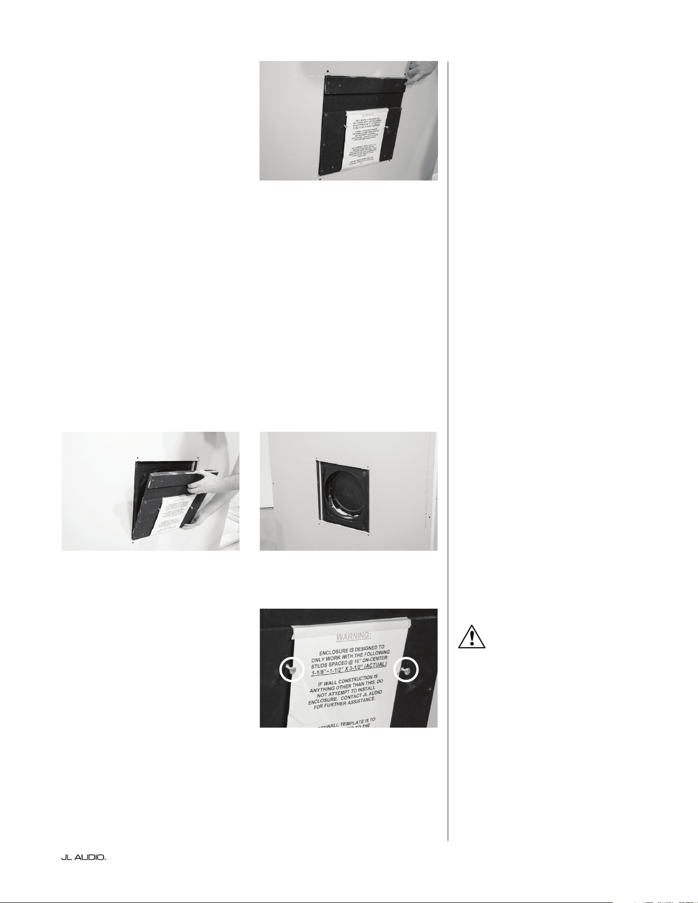
Mounting the Wallboard Template
e wallboard template is used to
temporarily secure the enclosure in
the wall cavity while also providing
a hard edge for the surrounding
wallboard installation. e wallboard
template is pre-attached to the
enclosure and must remain attached
until the surrounding wallboard
has been installed and the grille and
subwoofer are ready to be mounted.
Visually center the step at the rear
of the wallboard template to the inside
edges of the le and right wall studs,
(Figure 16) making sure you have the
same amount of clearance on either
side. Secure the wallboard template
in position using eight #8 x 1.25-inch
screws. (Figure 17)
Wiring the Enclosure
e nal step before the wallboard
installation is to route the speaker cable
down to the enclosure. Feed the speaker
cable through the previously drilled
holes (Figures 18 & 19) in the wooden
cross-member or through an adjacent
stud. Remove the outer jacketing to
expose the individual wires. (Figures
20 & 21)
Although the hanging rod is
padded to reduce vibrations, the wire
jacketing should remain in place as
far down the hanging rod as possible.
Secure the jacketed portion to the
rod using the supplied wire/cable ties.
(Figure 22)
Observing correct polarity,
remove the insulation from the
individual wires and connect to the
push terminals located on top of
the enclosure. (Figure 23) To reduce
the chances of noise and vibration,
position the individual wires (Figure
24)
so they do not come into contact
with any surrounding parts (enclosure,
mounting brackets, studs, wallboard
surfaces or any other surfaces within
the wall cavity). Any possible contact
point may lead to undesirable rattles
or buzzing, which will be inaccessible
once the surrounding wallboard has
been installed.
Figure 16 Figure 17
Figure 18 Figure 19
Figure 20
Figure 21
Figure 22 Figure 23
Figure 24
Page 15 | Fathom IWS
Installing the Wallboard
You may now proceed with
installing the surrounding wallboard
using the wallboard template as a hard
edge. e surrounding wallboard
should be installed ush against
the wallboard template on all sides.
(Figure 25)
Please note, it is critical that any
gaps between the wallboard template
and surrounding wallboard do not
exceed 1/8-inches (0.125 in/3.2 mm).
Removing the Wallboard Template
Once the surrounding wallboard
has been installed, verify that any gaps
between the wallboard template and
surrounding wallboard are no more
than 1/8-inches (0.125 in/3.2 mm).
Use joint compound to ll in any
spaces greater than 1/8-inches (0.125
in/3.2 mm).
To remove the wallboard template,
remove all twelve screws (4 inner and
8 outer) from the wallboard template
and pull forward (Figure 26 & 27) to
detach it. Note, there are four pins
behind the wallboard template used
for alignment with the enclosure, so
the template must be pulled straight
and away from the enclosure without
tilting for removal.
Once removed, any remaining pins
attached to the front of the enclosure
can be removed using pliers.
PRO-TIP:
You may nd it easier to partially
screw two screws into the center area
of the template to use as a grip as you
pull forward.
Install surrounding wallboard ush
against wallboard template.
Figure 25
Figure 26 Figure 27
PRO-TIP
| Fathom IWSPage 16
Installing the Grille Tray
e grille assembly includes a
plastic paint guard to protect the
woofer from overspray during
painting. e outer metal mesh grille
should be painted separately from
the grille tray to prevent them from
sticking together. To separate the metal
mesh grille from the grille tray, lay the
grille face down and li up on a corner
of the grille’s outer frame while holding
the center grille section down.
With the wallboard template
removed, test t (Figure 28) the grille
tray by inserting it into the opening.
Make sure the mounting holes along
the le and right sides of the grille
tray, are aligned with both stud faces.
e grille’s outer frame should be
level and make contact with the outer
wallboard surface. e inner metal
sleeve of the grille tray should t
into the woofer’s mounting area. e
woofer will mount directly through
the metal sleeve into the enclosure.
is will channel all of the woofer’s
energy through the grille opening
while ensuring the enclosure remains
decoupled from the wall. Once
you’ve veried that the grille tray ts
properly, secure it in place using the
six screws that were supplied with the
grille. (Figures 29-31)
Figure 28
Figure 29
Figure 30
Figure 31
Page 17 | Fathom IWS
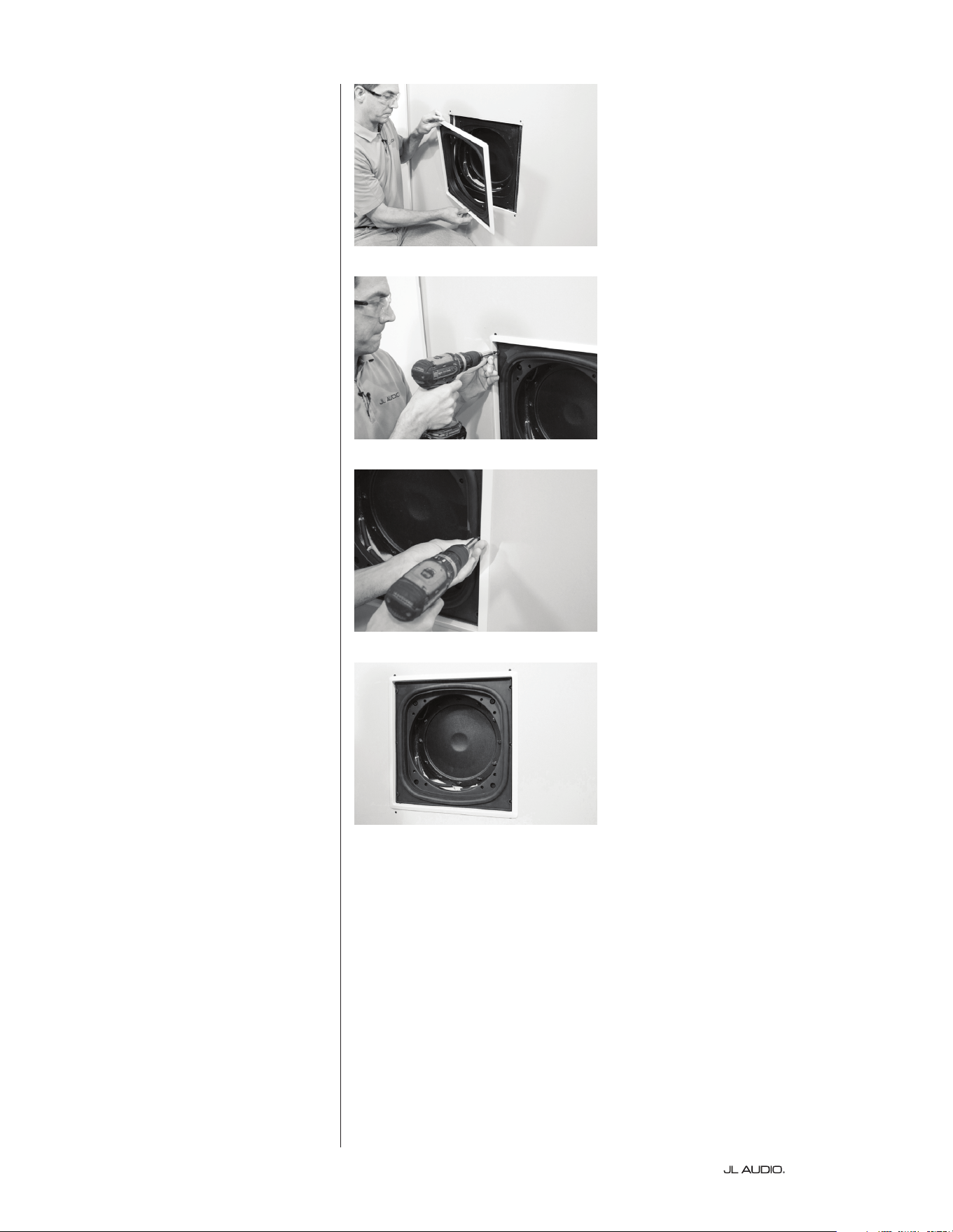
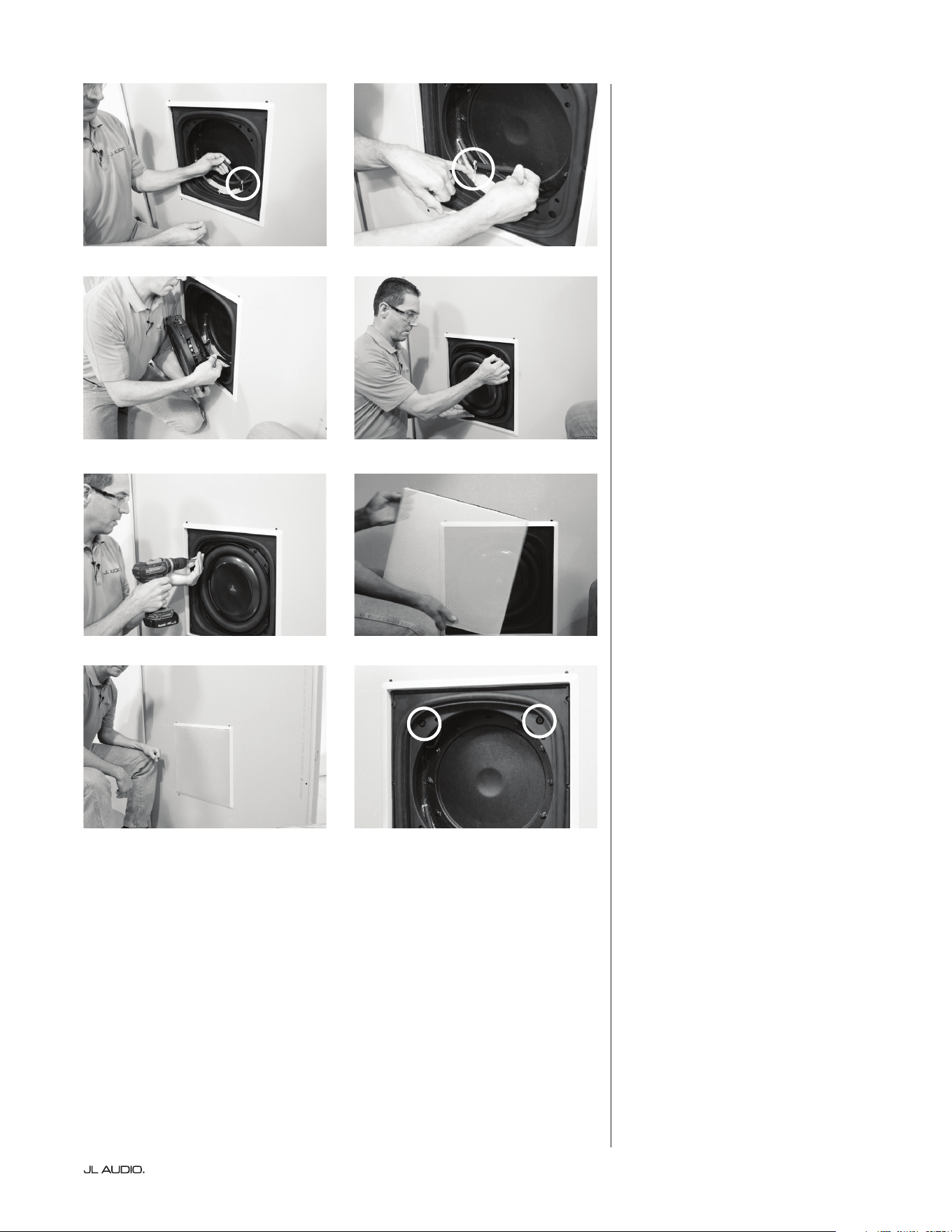
Installing the Subwoofer and Grille
Reach into the enclosure’s opening
and locate the two speaker leads.
Each lead is held in place by an elastic
band (Figures 32 & 33) to hold the
wires out of the way when mounting
the subwoofer. ese elastic bands
should not be removed. Position the
woofer with the JL Audio logo upright
and connect each speaker lead to
its respective terminal. (Figures 34)
e holes on the subwoofer’s frame
should line up with the holes in the
grille’s inner metal sleeve. (Figure 35)
Using the eight screws supplied with
the subwoofer, mount the subwoofer
through the grille’s inner metal sleeve
and into the enclosure.
(Figure 36)
Once the system has been
calibrated (see below), the metal
mesh grille may be installed. Insert
the painted metal mesh grille into
the grille’s frame, making sure the
notches in the metal mesh line up
with the screws that hold the grille in
place. (Figure 37-38)
Calibrating the Amplier
To facilitate calibration of the
Fathom IWS amplier with your
listening room, the Fathom IWS
enclosure includes front-mounted
speaker terminals (standard
banana jacks). ese terminals
(Figure 39) will allow the user to
temporarily connect the amplier
to the enclosure for calibration,
even if the enclosure is permanently
installed in the wall cavity. Refer
to the Owner’s Manual included
with your amplier for detailed
installation instructions and A.R.O.
calibration of your IWS system.
is completes the installation of the
Fathom IWS enclosure.
Figure 32 Figure 33
Figure 34 Figure 35
Figure 36
Figure 37
Figure 39
Figure 38
A.R.O. Calibration Jacks

| Fathom IWSPage 18
NOTES

Page 19 | Fathom IWS
NOTES
SKU#011423 08-2016
Printed in U.S.A.
www.jlaudio.com
10369 North Commerce Parkway • Miramar, Florida • 33025 • USA
“JLAudio”, “Ahead of the Curve”, “Fathom” and the JLAudio logo are registered trademarks of JLAudio, Inc.
©2016 JL Audio, Inc. • U.S. PATENTS: #5,734,734 #5,949,898 #6,118,884 #6,229,902 #6,243,479 #6,294,959 #6,501,844
#6,496,590 #6,441,685 #5,687,247 #6,219,431 #6,625,292 #D472,891 #D480,709 Other U.S. & Foreign patents pending.
Due to our policy of continuous product development, all specifications are subject to change without notice.
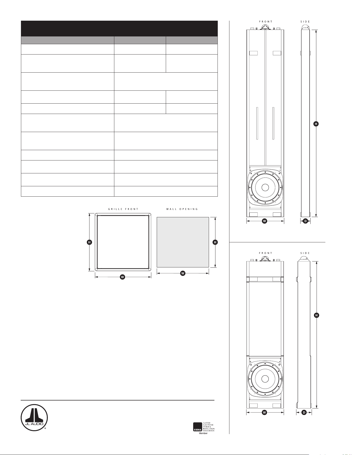
Fathom® IWS Enclosure Specifications:
Specifications Fathom® IWS-SYS-1 Fathom® IWS-SYS-2
Enclosure Type: Single Sealed Enclosure Two Sealed Enclosures
Driver(s):
13.5-in.
(nominal diameter)
13.5-in.
(nominal diameter)
in each of two enclosures
Frequency Response (anechoic):
26 Hz - 101 Hz (+/- 1.5 dB)
-3dB at 25 Hz / 112 Hz
-10dB at 22 Hz / 150 Hz
Effective Piston Area:
98.26 sq. in.
0.0634 sq. m.
196.51 sq. in.
0.1268 sq. m.
Effective Displacement: 147.3 cu. in. (2.41 liters) 294.6 cu. in. (4.82 liters)
2 x 4 Enclosure Dimensions:
(H) Height x (W) Width x (D) Depth
Measurements do not include padding material.
70 in. x 13.75 in. x 2.9 in.
1,778 mm x 349 mm x 74 mm
2 x 6 Enclosure Dimensions:
(H) Height x (W) Width x (D) Depth
Measurements do not include padding material.
55 in. x 13.75 in. x 4.70 in.
1,397 mm x 349 mm x 119 mm
Cabinet Finish: Black Texture-Coated
Grille Dimensions:
(H) Height x (W) Width
17.64 in. x 17.14 in.
448 mm x 435 mm
Wall Opening Dimensions:
(H) Height x (W) Width
16.5 in. x 16 in.
419 mm x 406 mm
Grille Finish: White (paintable)
“A” Box
“B” Box