
OWNER’S MANUAL
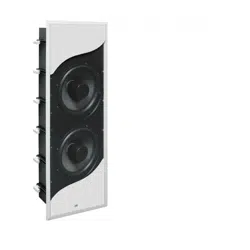
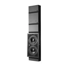
JBL® Synthesis SSW-3
IN-WALL SUBWOOFER

2
THANK YOU FOR CHOOSING JBL®
For more than 70 years, JBL has been involved in every aspect of music and film recording and reproduction, from live performances to
monitoring the recordings you play in your home, car or office.
We are confident that the JBL Synthesis loudspeaker you have chosen will provide every note of enjoyment that you expect – and that
when you think about purchasing additional audio equipment for your home, car or office, you will once again choose JBL.
Please take a moment to register your product on our website at www.jblsynthesis.com. This enables us to keep you posted on our latest
advancements, and helps us to better understand our customers and build products that meet their needs and expectations.
All features and specifications are subject to change without notice.
INCLUDED
1. 1 x SSW-3 Subwoofer
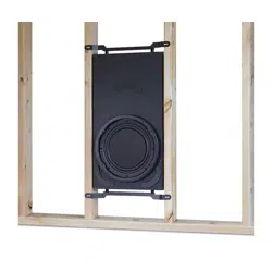
2. 1 x SSW-3BB back box
3. 1 x Grille
4. 1 x Scrim cloth for grille
5. 1 x Owner’s Manual
6. 2 x Centering Blocks (Pre-Mounted)
7. 1 x Spacer (For 0.625” Drywall)
8. 1 x Center Spacer (For 0.625” Drywall)
9. 20 x Screws (For Baffle Assembly)
10. 1 x lining material 6”x6”
11. 2 x Styrofoam blocks (For used as BB support)
12. 2 x Wood Screws M6 x 30mm (For filling-up screw holes when upper centering block is removed)
13. 10 x Polyurethane Bushings (For BB Mountin g to Wall Stud)
14. 10 x Flat Washers (For BB Mounting to Wall Stud)
15. 10 x ø5 x 90MM (For BB Mounting to Wall Stud)
PLACEMENT
Low-frequency sounds are normally omnidirectional, meaning the listener can’t tell where they are generated from. However, frequencies
between 75Hz and 150Hz can be localized, especially at higher volume levels. Positioning your subwoofer as recommended will provide
the most natural soundstage and imaging from your loudspeaker system.
It is generally recommended that you install your SSW-3 in-wall subwoofer along the same wall as the front loudspeakers. The SSW-3
subwoofer is not video-shielded and should not be placed near a video display. Installing the SSW-3 near a corner will tend to maximize
low-frequency output. Be cautious when installing in a corner, to avoid a “boomy” sound. Also take into consideration any unusual
features of the room, such as an alcove, which may tend to create a localized node that may affect bass response in that area of the room.
It is also recommended that the speaker is installed so that the bottom of the speaker is approximately 12” from the floor. Using the SSW-
3BB back box enclosure will ensure that the loudspeaker is installed at the ideal height. This is to help with the low-frequency loading
(bass reinforcement). This also helps hide the speaker in a less visible place. In special circumstances, it is acceptable to install the speaker
at any height on a wall.
Remember that these are just guidelines. Since every listening room is different, JBL strongly recommends experimenting with the positioning
of your subwoofer prior to cutting the wall to obtain the most pleasing results in your room. One technique that can help you find the ideal
subwoofer location is to temporarily borrow a stand-alone subwoofer and place it near the main listening location. Then move around the
room and determine where you hear the most pleasing bass performance. This would then be the ideal location for the subwoofer.
When using two SSW-3 in-wall subwoofer systems, you may need to be concerned about phase, as the sound waves may cancel each
other out. If the bass response seems low, try inverting the polarity on one subwoofer – i.e., connect the (+) terminal on the amplifier to
the (–) terminal on the speaker, and the (–) terminal on the amplifier to the (+) terminal on the speaker.

3
www.jblsynthesis.com
English
SPEAKER CONNECTIONS
Since the SSW-3 is a passive subwoofer, only speaker-level connections are available. The SSW-3 subwoofer is specically designed
for use in conjunction with the JBL® Synthesis SDA ampliers. It is optimized to oer the best dynamics and frequency response with
the use of the JBL SDA-4600 amplier, which is specially designed to use the proprietary SSW-3 tuning le and drive the signature
reactive load impedance of the SSW-3. When using a dierent SDA amplier with the SSW-3, contact your certied Synthesis installer
for correct adjustment and loading of the SSW-3 tuning le. The SSW-3 is capable of running o of one SDA-4600 amplier channel.
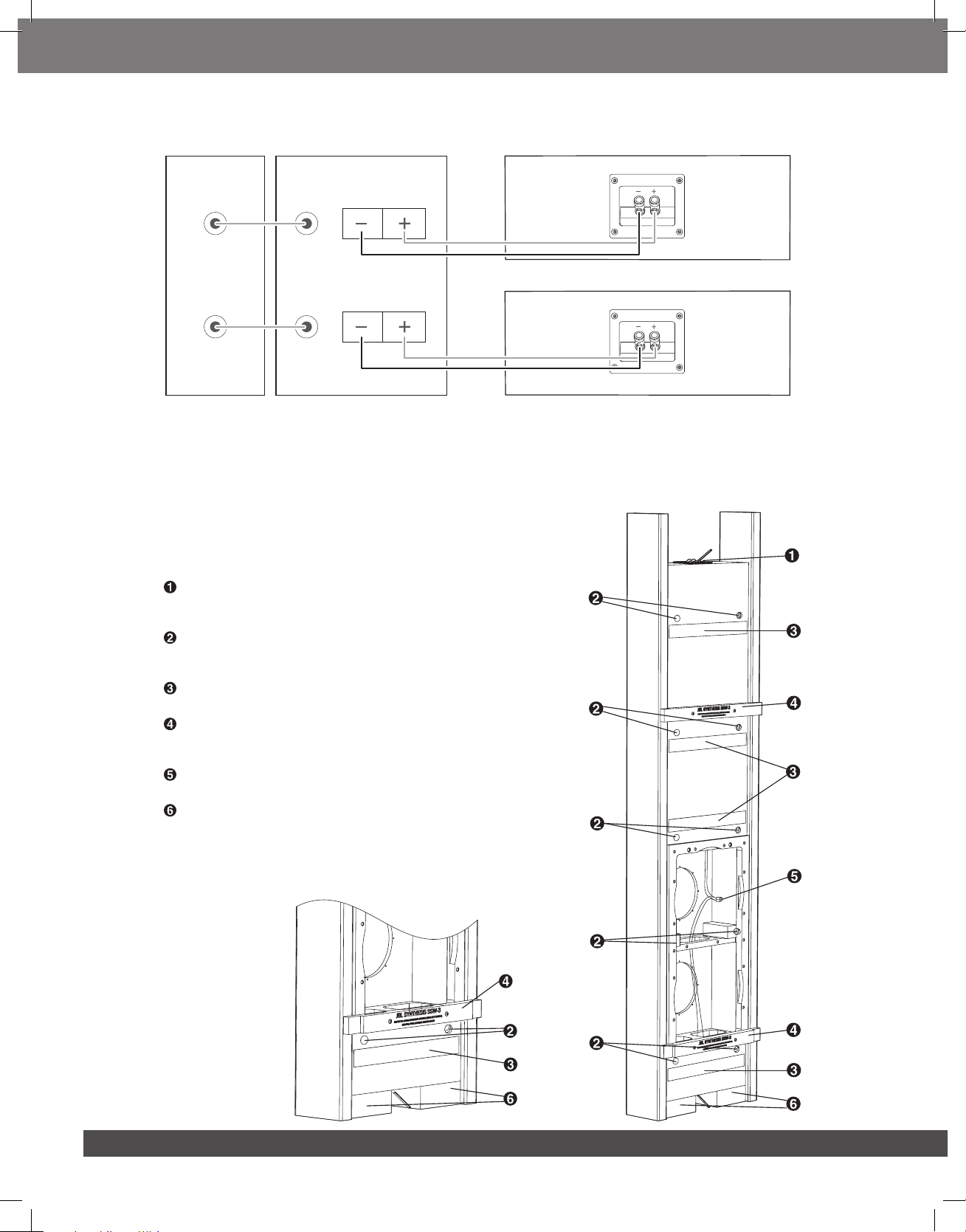
Speakers and electronics have corresponding (+) and (–) terminals. Most manufacturers of speakers and electronics, including JBL, use red
to denote the (+) terminal and black for the (–) terminal. It is important to connect both speakers identically: (+) on the speaker to (+) on
the amplifier, and (–) on the speaker to (–) on the amplifier. Wiring “out of phase” results in thin sound, weak bass, and a poor stereo image.
With the advent of multichannel surround sound systems, connecting all of the speakers in your system with the correct polarity remains
equally important in order to preserve the proper ambiance and directionality of the program material.
If two SSW-3 subwoofers are used, the wires for both speakers should be the same length. If one speaker is placed closer to the amplifier than
the other, hide the excess wire behind the wall. If the bass response seems low, there may be a phase problem, with the sound waves from
the two subwoofers canceling each other out. If the bass response seems low, try inverting the polarity on one subwoofer – i.e., connect
the (+) terminal on the amplifier to the (–) terminal on the speaker, and the (–) terminal on the amplifier to the (+) terminal on the speaker.
To connect the SSW-3 baffle, support the baffle on the lower baffle opening. See the “Installation Guide” section about applying the 0.625” spacer
to the back box opening. Locate the wire pair in the back box that terminate in the polarized locking connector. Dress this end of the wire to
go through any brace openings necessary so as to have a direct connection to the short wire leads from the baffle with the mating polarized
locking connector. Make sure that the wire path is such that when you rock the baffle onto the back box opening and install and tighten the
baffle mounting screws, that no wire is trapped between the baffle and the brace. Connect the polarized locking connector from back box wire
lead to the mating connector on the lead from the baffle. They should connect easily. If it feels like a force fit, re-examine the connector mating
and turn the connectors as necessary to make the correct attachment before plugging them together. Make sure you here a “click” sound from
the lock. As you rock the baffle back to install it, make sure to place the 6” x 6” piece of insulation material between the baffle and the attached
polarized locking connectors to make sure that they do not rattle against the baffle interior. If you have 5/8” wallboard and applied the 0.625”
spacer for the baffle perimeter, make sure to apply the 0.625” center spacer for the brace before settling in the baffle to screw it to the back box.
To use the push-type terminals on either end of the SSW-3 back box, depress the colored cap until the pass-through hole in the binding
post is revealed. While holding the cap down, insert the bare end of the wire, or a banana plug, into the passthrough hole. Release the cap
and tug gently on the wire to ensure that it is secure.
Note: We recommend that you run the wire first, then connect it to the back box, then install the back box, then install the baffle, and
finally connect the wire to your power amplifier.
Connect your main receiver or processor’s line-level subwoofer output to the line-level input on your subwoofer amplifier.
After you have installed the SSW-3BB back box enclosure as described in the next section, connect the other end of the wire from the
SSW-3 back box to the speaker output terminals on your subwoofer power amplifier, making sure to observe the correct polarity.
You may prefer to use two SSW-3 subwoofer systems in Stereo mode for improved performance and superior imaging. Use two mono
subwoofer amplifiers, each connected to either the left or right subwoofer output on your receiver/processor, or use a single two-channel
subwoofer amplifier and connect the left and right line-level subwoofer outputs on your receiver/processor to the corresponding inputs
on your amplifier. Then connect the positive and negative terminals for each channel to one SSW-3 subwoofer system.
Wire Length Recommended Size
Up to 20 ft. 16-gauge
Up to 30 ft. 12-gauge
Greater than 30 ft. 10-gauge
USING ONE SSW-3 SUBWOOFER IN MONO MODE
AmplierReceiver/Processor
Subwoofer
Out
Line-Level
Inputs
Speaker-Level
Outputs
Top/bottom of SSW-3BB back box
4
USING TWO SSW-3 SUBWOOFER IN STEREO MODE
Receiver/Processor Amplier
Subwoofer or
main Amp out
Left
Right
Right
Left
Right
Left
Line-Level
Inputs
Speaker-Level
Outputs
Left top/bottom of SSW-3BB back box
Right top/bottom of SSW-3BB back box
INSTALLATION GUIDE
A complete SSW-3 loudspeaker system includes the SSW-3 in-wall subwoofer and the SSW-3BB back box. These components are packaged
separately.
Installation requires access to the space between the wall studs. Therefore, in new-construction applications, the SSW-3BB back box is
installed before the wallboard.
For existing construction, carefully remove a section of wallboard that reveals the studs
on either side of the bay where the back box will be installed, enabling the board to be
screwed back onto the studs after installation is complete. Store the wallboard in a safe
place until the speaker installation is complete.
Terminal Cup: Connect the speaker wires from your subwoofer amplifier to these
terminals. You may also use the terminal cup located at the bottom of the back box.
The terminal cups are wired in parallel so either may be used.
Mounting Holes for Bushings: The SSW-3 uses a system of bushings to act as
springs that isolate the speaker from room and wall vibrations. Mount the bushings
in each of these holes.
Damping Pads: These pads are part of the isolation system to prevent unwanted
resonances. They should be left in place as is.
Centering Bars: Screw these bars onto the SSW-3BB back box using the included
flat-head screws. The bar ends butt against the studs to keep the back box depth
correct, and may be attached during installation.
Speaker Wires: Connect the polarized locking connector from back box wire lead
to the mating connector on the lead from the baffle.
Styrofoam Blocks: These blocks support the SSW-3BB back box and ensure that it
is mounted within the stud bay at the correct height for optimum performance.
They also help to isolate the speaker system from room resonances.
Detail A:
Detail A:
5
5
www.jblsynthesis.com
English
Installation:
1. Place the Styrofoam™ blocks on the bottom plate of the stud bay. The SSW-3BB back box will rest on top of the blocks.
2. Install the two centering bars as shown in Detail A. The centering bars are for setting the depth of the enclosure. They also help
locate the horizontal position of the enclosure as they are mounted into the studs at the left and right to hold the enclosure in the
correct location.
3. Attach amplifier output wire to the nearest end of the back box. If the wire is not run yet, run this through the wall first, and attach
as noted. Fit the enclosure into the wall. The bottom of the SSW-3BB back box will rest on top of the Styrofoam blocks that you
put on the baseboard two-by-four in Step 1.
4. At this time, you may want to screw through each side of the wood centering bars to mount the enclosure to the studs. This will
hold the enclosure in position.
5. Install each of the ten bushings into their mounting holes . Insert one end of the rubber bushing into the hole, then place a flat
washer onto the shaft of a supplied 5” deck screw, insert the screw into the bushing and then screw the deck screw through the
bushing and into the wall stud.
6. The enclosure is now installed and ready for the wall-board to be installed over it. Remove the wood centering bars and use the
wood screws to close up the holes in the SSW-3BB back box. The drywall cutout dimensions are 26” (H) x 15” (W) (660.4mm x
381mm).
7. Note that it would be wise at this step to connect the baffle polarized locking connectors together and the other end of the speaker
wire to the amplifier and run a low-level test to make sure that the back box is properly connected to the amplifier. Once correct
connection is verified, disconnect the baffle and the speaker wire from the amplifier and proceed.
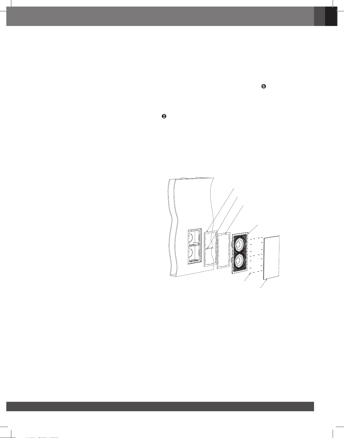
8. Determine your wallboard thickness. If it is ½”, proceed
to baffle installation (#9, this page). If it is 5/8”, then
add the included 1/8” rectangular spacer to the edge
of the opening and remove the PSA backing on the
1/8” rectangular strip spacer and attach this to the top
surface of the brace.
9. Connect the wires with the polarized locking
connector to the baffle following the instructions
noted in “Speaker Connections.” Do not forget to cover
the extra wire and mated connectors with the 6” x 6”
piece of lining material. Settle the baffle into place in
the opening.
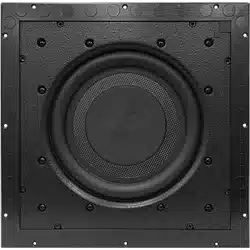
10. Install the SSW-3 baffle into the SSW-3BB back box
using the twenty screws, as shown in the illustration
at right.
11. Attach the grille by lining up one end of the grille just
outside the baffle and then slowly bringing the other
end of the grille near to the baffle and releasing. Note
that the grille attachment magnets are energetic, so
bring the grille within about 1/16” before releasing to
minimize the risk of any damage to the baffle, grille,
or wall.
SPACER FOR
.625" DRYWALL
SSW3- SUBWOOFER
BAFFLE ASSY
GRILLE
Installed Back Box with finished .625"
drywall
SCREWS (20)
BAFFLE TO SPACER GASKET
CENTER SPACER FOR
.625" DRYWALL
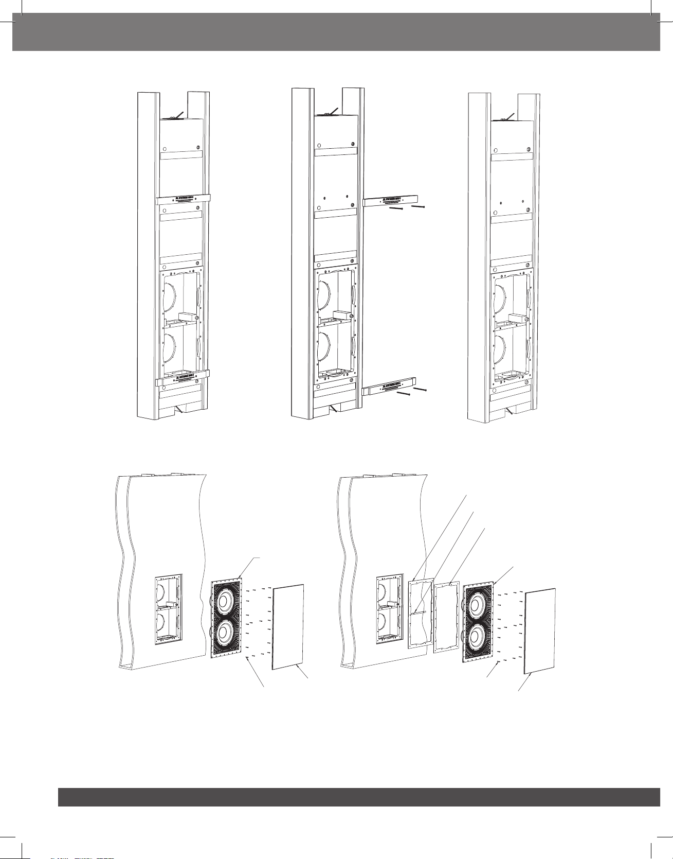
6
Back Box with attached centering
blocks (pre-mounted)
positioned and installed into stud bay.
After Back Box installation
and centering blocks are removed,
use wood screws to fill the upper (2)
holes in the SSW3-BB, lower (2) holes
will be sealed by the baffle gasket.
After Back Box installation
remove centering blocks
SPACER FOR
.625" DRYWALL
SSW3- SUBWOOFER
BAFFLE ASSY
GRILLE
Installed Back Box with finished .625"
drywall
SCREWS (20)
BAFFLE TO SPACER GASKET
CENTER SPACER FOR
.625" DRYWALL
SSW3- SUBWOOFER
BAFFLE ASSY
GRILLE
SCREWS (20)
Installed Back Box with finished .500"
drywall
Note: In some installations the top end of the cabinet may not be easily accessible after installation. Others may work best with the
woofers toward the ceiling rather than the floor. Due to these two factors, we have installed parallel-wired input terminals on each end of
the SSW-3. You only need to connect to one set of terminals, and so can use the set most accessible.
7
www.jblsynthesis.com
English
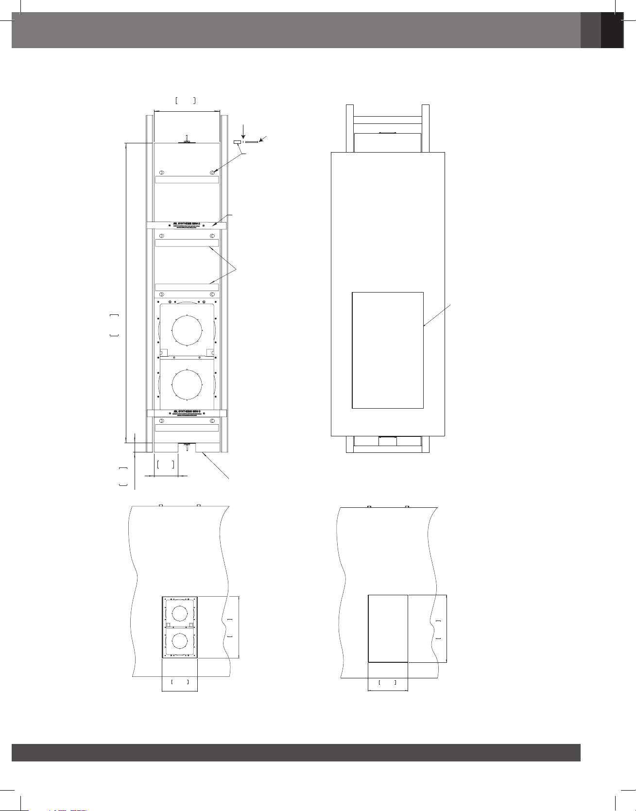
DIMENSION DRAWINGS
CUTOUT DRYWALL
CUTOUT DRYWALL
5.125
130.18
2.000
50.80
64.000
1625.60
14.000
355.60
STYROFOAM BLOCKS
DAMPING PADS
POLYURETHANE
(RUBBER) FINAL
MOUNTING
DECK SCREW
WASHER
CENTERING PADS
15.000
381
660.40
26.000
BAFFLE
BAFFLE
16.890
429
28.425
722
COVER / TEMPLATE
8
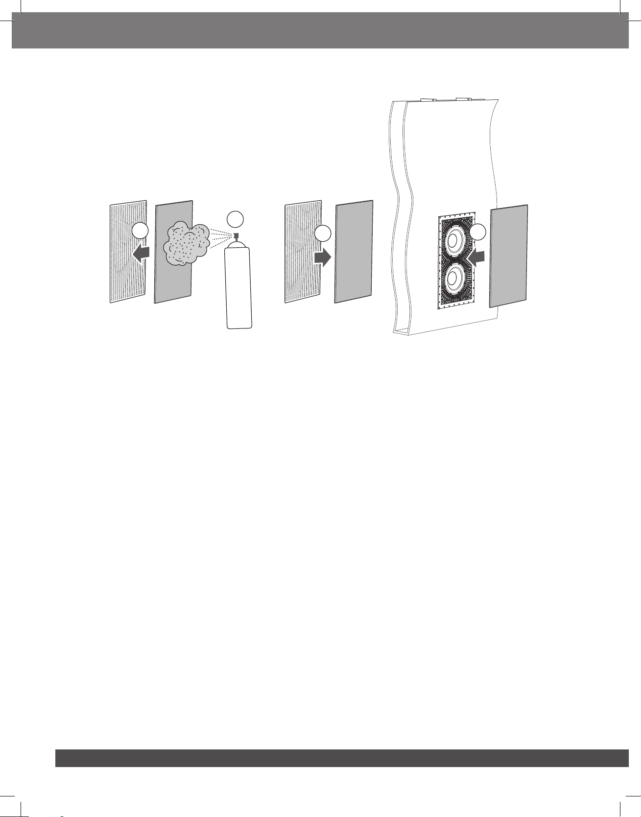
PAINTING THE GRILLE
1
3
2
4
1. Carefully remove scrim cloth from the rear of the grille. Clean grille on both sides with alcohol. You can cover the edge trim with
masking tape if desired.
2. When the alcohol has evaporated, place the grille on scrap cardboard in an open area away from sensitive surfaces. Paint the front
of the grille in light amounts by multiple passes with the spray can or gun. Try to keep an even spray and avoid building up the
thickness of the paint too fast. If any holes are blocked with paint, open them up with a pin or small wire. Use appropriate safety
clothing and protection for this step!
3. Once the paint is dry, turn the grille over, and reapply the scrim cloth to the back of the grille. If the scrim cloth was torn or damaged
upon removal, you can use the enclosed spare cloth. If the cloth no longer wants to stick to the back, you can apply light amounts
of a spray adhesive, such as 3M 77 to the back of the grille, and then attach the scrim cloth. Make sure that no spray adhesive makes
foam or blocks holes.
4. Attach the grille to the SSW-3 using instruction #11 on page 5.

9
www.jblsynthesis.com
English
TROUBLESHOOTING
Symptom Solution
If there is no sound from any of the speakers
• Check that the receiver/amplifier is on and that a source is playing.
• Check all wires and connections between the receiver/amplifier and the speakers.
Make sure all wires are connected. Make sure none of the speaker wires are frayed,
cut, punctured or touching each other.
• Review the proper operation of your receiver/amplifier.
If there is no sound coming from one speaker
• Check the Balance control and channel output level settings on your receiver/
amplifier.
• Check all wires and connections between the receiver/amplifier and the speakers.
Make sure all wires are connected. Make sure none of the speaker wires are frayed,
cut, punctured or touching each other. In multichannel applications, make sure
that your receiver/processor has been configured to enable all channels that you
are using.
If there is low (or no) bass output, or you are
hearing only midrange frequencies (such as
vocals) through the subwoofer
• Make sure the connections to the speaker inputs have the correct polarity (+
and –). If you are using two SSW-3 subwoofers, try inverting the polarity on one
subwoofer.
• Some processors (receivers) and surround modes may have the subwoofer output
disabled initially. Consult your processor or receiver manual to learn how to
enable the subwoofer output.
• The crossover frequency to the subwoofer may be set too high. Consult your
processor or receiver manual to learn how to lower your subwoofer crossover
frequency.
If the system plays at low volumes but shuts
off as the volume is increased
• Check all wires and connections between the receiver/amplifier and the speakers.
Make sure all wires are connected. Make sure none of the speaker wires are frayed,
cut, punctured or touching each other.
• If more than one pair of main speakers are being used, check the minimum-
impedance requirements of your receiver/amplifier.
SPECIFICATIONS
Frequency Response 20 Hz – 150 Hz (-6 dB)
Maximum Recommended Amplifier Power 600 Watts RMS per channel
Impedance 4 Ohms nominal
Sensitivity 88dB (2.83 V / 1m), both woofers driven
Woofer Dual 10"/250 mm composite cones woofers
Dimensions of SSW-3BB enclosure (H x W x D) 64” x 14” x 5.1” (1626 mm x 356 mm x 130 mm)
Mounting Cutout Size (W x H) 15.5” x 66” (393.7 mm x 1676.4 mm)
Grille Size (W x H x D) 16.890” x 28.425” x 0.375” (429 mm x 722 mm x 9.53 mm)
Weight per Speaker 81 lb (36.75 kg)
All features and specifications are subject to change without notice.
The maximum recommended amplifier power rating will ensure proper system headroom to allow for occasional peaks. We do not
recommend sustained operation at these maximum power levels.
JBL, Harman International, JBL Synthesis and Synthesis are trademarks of Harman International Industries, Incorporated, registered in the
United States and/or other countries.
Styrofoam is a trademark of the Dow Chemical Company.

Please visit JBL.COM / JBLSYNTHESIS.COM for additional language support on the user manual.
Veuillez visiter JBL.COM / JBLSYNTHESIS.COM pour obtenir le mode d'emploi en d'autres langues.
Visita JBL.COM / JBLSYNTHESIS.COM para obtener el manual de usuario de soporte en idiomas adicionales.
Weitere Sprachfassungen der Bedienungsanleitung findest Du unter JBL.COM / JBLSYNTHESIS.COM.
Если вам требуется дополнительные версии руководства пользователя на других языках, посетите сайт JBL.COM / JBLSYNTHESIS.COM.
別の言語に対応したユーザーマニュアルを読むには、JBL SYNTHESIS.COMにアクセスしてください。
请访问 JBL.COM / JBLSYNTHESIS.COM 以获取其他语言版本的用户手册。
Торговая марка: JBL
Назначение товара: Пассивная акустическая система
Изготовитель: Харман Интернешнл Индастриз Инкорпорейтед, США, 06901 Коннектикут, г.Стэмфорд, Атлантик
Стрит 400, офис 1500
Страна происхождения: Китай
Импортер в Россию: OOO “ХАРМАН РУС СиАйЭс“, Россия, 127018, г.Москва, ул. Двинцев, д.12, к 1
Гарантийный период: 1 год
Информация о сервисных центрах: www.harman.com/ru тел. +7-800-700-0467
Срок службы: 5 лет
Товар не подлежит обязательной сертификации
Дата производства: Дата изготовления устройства определяется по двум буквенным обозначениям из второй
группы символов серийного номера изделия, следующих после разделительного знака «-».
Кодировка соответствует порядку букв латинского алфавита, начиная с января 2010 года:
000000-MY0000000, где «M» - месяц производства (А - январь, B - февраль, C - март и т.д.) и «Y» -
год производства (A - 2010, B - 2011, C - 2012 и т.д.).
Используйте устройство только по прямому назначению в соответствии с предоставленной инструкцией. Не пытайтесь самостоятельно
вскрывать корпус товара и осуществлять ремонт. В случае обнаружения недостатков или дефектов, обращайтесь за гарантийным обслуживанием
в соответствии с информацией из гарантийного талона. Особые условия хранения, реализации и (или) транспортировки не предусмотрены.
Избегайте воздействия экстремальных температур, долговременного воздействия влаги, сильных магнитных полей. Устройство предназначено для
работы в жилых зонах. Срок годности не ограничен при соблюдении условий хранения.
产品中有害物质的名称及含量
部件名称 目标部件
有害物质或元素
铅(Pb)
汞
(Hg)
镉
(Cd)
六价铬
(Cr(VI))
多溴联茉
(PBB)
多溴二苯醚
(PBDE)
电路板
印刷电路板,电路板上的电子零件(不包括特
定电子零件),内部相关连接线
X 0 0 0 0 0
框体 外 壳,面 板,背 板 等 X 0 0 0 0 0
特定电子零
部件
变压器,保险丝,大型电解电容,电源插座 X 0 0 0 0 0
附件 电线,说明书,包装等 X 0 0 0 0 0
本表格依据SJ/T 11364的规定编制
O:表示该有害物质在该部件所有均质材料中的含量均在GB/T 26572 规定的限量要求以下。
X:表示该有害物质至少在该部件的某一均质材料中的含量超出GB/T 26572规定的限量要求。
在中华人民共和国境内销售的电子电气产品上将印有”环保使用期”(EPuP)符号。
圆圈中的数字代表产品的正常环保使用年限。


HARMAN International, Incorporated
8500 Balboa Boulevard, Northridge, CA 91329 USA
www.jblsynthesis.com
© 2019 HARMAN International Industries, Incorporated. All rights reserved.
JBL is a trademarks of HARMAN International Industries, Incorporated, registered in the United States
and/or other countries.
Features, specifications and appearance are subject to change without notice.
Part No. 950-0562-001