09.26.17
Before Installation
1. Determine the location for the subwoofer(s).
2. Perform an obstruction survey using a stud nder to be
certain that there are no obstructions.
3. Position the included cutout template where the subwoofer
is to be located and pencil an outline on the wall. The cut-
out for the VPSUB is 12 3/4” x 12 3/4” (324mm x 324mm).
4. Cut the mounting hole using a keyhole or drywall saw and
run the subwoofer wires from the mounting hole to the
amplier location.
NOTE: CONSULT LOCAL BUILDING CODES BEFORE RUNNING
SUBWOOFER WIRES THROUGH WALLS.
Installation
1. Strip 1/4” – 1/2” (6mm – 12mm) of insulation from each
subwoofer lead.
2. Twist the strands or tin the exposed wire with solder to
ensure that there are no stray strands.
NOTE: STRAY STRANDS THAT TOUCH EACH OTHER CAN CAUSE A
SHORT-CIRCUIT THAT CAN DAMAGE THE AMPLIFIER.
3. The subwoofer’s terminals are spring-loaded. Push the top
of each terminal down to open the connector and insert the
exposed wires (see Figure 1).
4. The subwoofer’s positive spring terminal is labeled with a red
dot; the negative spring terminal is labeled with a black dot.
5. Each VPSUB should be driven by a dedicated channel of a
DSP 2-150 or DSP 8-130 MKII amplier. Be sure to select
the corresponding EQ preset in the amplier using SONARC.
Box Contents
(1) Quickstart Guide
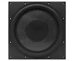
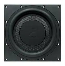
(1) Visual Performance in-wall subwoofer (VPSUB)
(1) Cut-out template
NOTE: VPSUB SHOULD BE PAIRED WITH A DSP 2-150 OR A
DSP 8-130 MKII AMPLIFIER (SOLD SEPARATELY).
7. When installing into double drywall or other thicker wall
materials, you may need to remove part of the two-piece
toggle feet. Use a small screwdriver to gently release the two
locking levers (see Figure 3).
Figure 1: Inserting the Exposed Wires
NOTE: THE ROTOLOCK
®
SYSTEM CAN ACCOMMODATE A WALL
MATERIAL THICKNESS OF 1 1/4” (32MM) WITH THE TOGGLE FOOT
CAP REMOVED THE SYSTEM CAN ACCOMMODATE A WALL
MATERIAL THICKNESS OF 1 7/8”(48MM).
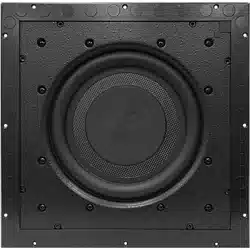
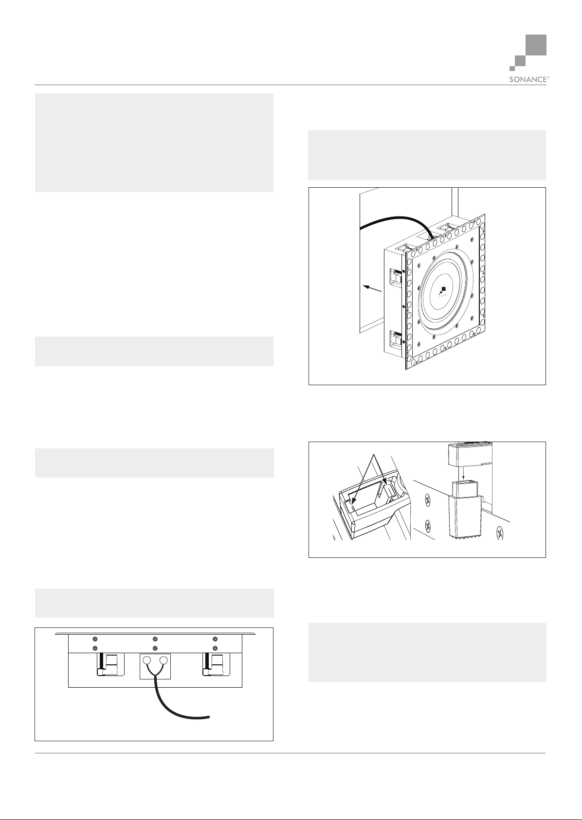
6. Make sure all the RotoLock
®
toggle feet are retracted so
that they can t within the mounting hole. Insert the
subwoofer into the hole in the wall (see Figure 2).
Locking Levers
Remove
Cap
Locking Levers
Figure 3: Releasing the Two Locking Levers
Figure 2: Tightening the RotoLock
®
Screws
33-7916
8. Tighten the screws on the front of the subwoofer bae.
The RotoLock
®
toggle feet will automatically rotate into
position and begin clamping the subwoofer. When you
notice resistance on the screws the speaker has been
clamped successfully.
9. The micro-trim grille is held in place by several small,
powerful magnets on the speaker frame. Place the grille
against the subwoofer and the magnets will hold it rmly in
place. When properly installed, the grille trim should make
contact with the wall all the way around the subwoofer.
NOTE: WITHOUT THE EQ PRESET, THE VPSUB OUTPUT WILL BE
SEVERELY LIMITED.
IMPORTANT: ALWAYS USE LOW-TORQUE SETTINGS; NEVER OVER
TIGHTEN. NOTE: ADJUSTING THE TENSION OF THE ROTOLOCK
®
CLAMPS SO THAT THE SUBWOOFER FRAME IS FLAT WILL HELP
ENSURE THAT THE GRILLE CONTACTS THE WALL ALL THE WAY
AROUND THE SUBWOOFER FOR A PROPER FIT.
©2017 Sonance. All rights reserved. Sonance is a registered trademark of Dana Innovations. Due to continuous product improvement, all features and specications are subject to change
without notice. For the latest Sonance product specication information visit our website: www.sonance.com
SONANCE • 991 Calle Amanecer • San Clemente, CA 92673 USA • Phone: (949) 492-7777 • FAX: (949) 361-5151 • Technical Support: (949) 492-7777
VPSUB QUICKSTART GUIDE
VISUAL PERFORMANCE SUBWOOFER