Loading ...
Loading ...
Loading ...

15
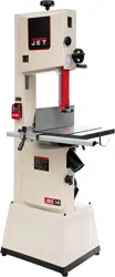
Figure 6-1
6.2 Voltage conversion
To convert the JWBS-14SFX from 115V to 230V,
single phase operation:
1. Disconnect band saw from power; unplug.
2. Switch the lead wires inside motor junction box,
according to diagram affixed to inside of
junction box cover.
3. Disconnect the 110V electrical socket at rear
of saw frame. This socket will not be used
when the band saw is drawing 230V power.
4. The 5-15P attachment plug supplied with the
band saw must be replaced with a UL/CSA
listed plug suitable for 230V operation.
6.3 Extension cords
The use of extension cords is discouraged; try to
position your machine within reach of the power
supply. If an extension cord becomes necessary,
make sure the cord rating is suitable for the
amperage listed on the machine’s motor plate. An
undersized cord will cause a drop in line voltage
resulting in loss of power and overheating.
Use Table 2 as a general guide in choosing the
correct size cord. If in doubt, use the next heavier
gauge. The smaller the gauge number, the heavier
the cord.
Recommended Gauges (AWG) of Extension Cords
Ampere
Rating
Volts
Total length of
cord in feet
More
Than
Not
More
Than
120
240
25
50
50
100
100
200
150
300
AWG
0 6 18 16 16 14
6 10 18 16 14 12
10 12 16 16 14 12
12 16 14 12
Not
Recommended
Table 2
7.0 Adjustments
7.1 Resaw fence
Refer to Figure 7-1.
The fence can be installed in one of two positions;
vertical (resaw position) or horizontal. Horizontal
position is useful for small or thin workpieces, and
allows blade guide to be lowered without
interference from fence. Zero setting of cursor
cannot be used with horizontal fence position.
Figure 7-1: fence positions
7.2 Miter gauge (optional accessory)
Refer to Figure 7-2.
1. Slide miter gauge (not included, optional
accessory) into table slot from front edge of
table.
2. Loosen knobs (A
1
) and install miter fence (A
2
)
onto gauge body. Position fence as needed and
tighten knobs.
3. Loosen handle (A
3
), pull out pin (A
4
), and rotate
body to desired angle. Tighten handle.
Figure 7-2: miter gauge adjustments
7.2.1 Setting positive stops
The miter gauge has positive stops at 0 (90°), and
45° left and right, located beneath the gauge body.
4. Use a square to verify that miter fence is square
to blade when set at 90° on scale
Loading ...
Loading ...
Loading ...
