
RPS-0097 07/17 Effective for models with serial numbers beginning with “J”.
Instruction Sheet
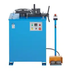
B2000 Cyclone
®
Bender
IMPORTANT RECEIVING INSTRUCTIONS
Visually inspect all components for shipping damage. If shipping damage is found, notify carrier at once. Shipping damage is
NOT covered by warranty. The carrier is responsible for all repair and replacement costs resulting from damage in shipment.
SAFETY ISSUES
IMPORTANT – USER SAFETY AND PROTECTION: In setting up systems to fit your operations, care must be taken to select the proper components
and design to insure appropriate that all safety measures have been taken to avoid the risk of personal injury and property damage from your
application or system.
GARDNER BENDER IS NOT RESPONSIBLE FOR DAMAGE OR INJURY CAUSED BY UNSAFE USE, MAINTENANCE OR THE APPLICATION OF
ITS PRODUCTS. Please contact Gardner Bender for guidance when you are in doubt as to the proper safety precautions to be taken in designing
and setting up your particular application
.
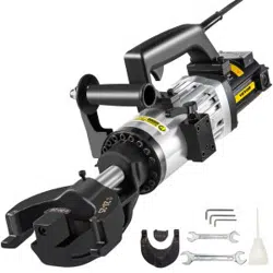
Figure 1. B2000 Cyclone
®
Bender
1.0 DESCRIPTION
• Engineered to save time; bends 0.5 inch to 2 inch
Rigid, Rigid aluminum, EMT and IMC conduit with
a single shoe and no loose parts
• Easy dial settings create accurate bends every time
and make training time virtually non-existent
• Bends in both horizontal and vertical positions to create
accurate offset bends
• Quickly creates repeated bends at the same degree
• Strong legs offer increased jobsite durability (10x life test)
• Large tires/wheels - increase mobility
• Strong upright handle provides ease of use
• Easily lift and transport using the forklift tubes built into base
• Lift Hook for security (job-site) tethering
• Incorporates storage area for tools, etc. while in use
• Includes Weather-Resistant Cover
The Cyclone
®
, GB model B2000 production bender is used to bend
EMT, IMC, rigid steel or rigid aluminum conduit. A single bending
shoe accommodates sizes
1
⁄2",
3
⁄4", 1", 1
1
⁄4", 1
1
⁄2" and 2" conduit.
The shoe is driven by a 115 V, 15 A motor. The roller housing
consists of a single urethane roller support arm, and three sets of
nylon rollers.
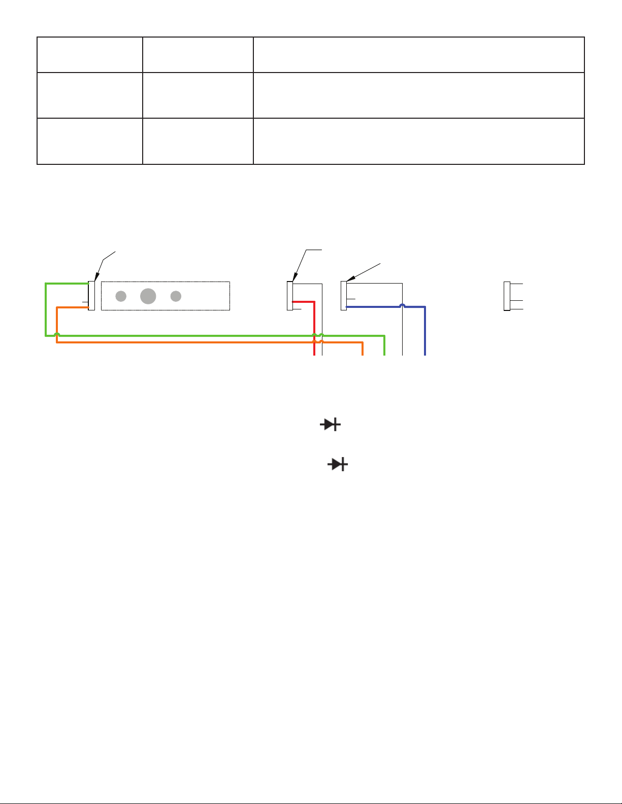
The bender control pendant consists of a zero light, a green power
light, a jog push button, a push button for “Bend and Return”. An
8’ electrical cord connects the pendant to the bender frame. The
bender can be used in a horizontal or vertical position.
The end plate contains an ON-OFF switch which is also a circuit
breaker. When the switch is turned on, the two leds will flash red,
then green to indicate normal function.
To avoid damaging the bender control circuit, an input voltage
sensing system is built into the control circuit. If input voltage is less
than 92 VAC or higher than 132 VAC the bender will shut off. One of
the two LEDS located on the end plate will light to indicate whether
high or low voltage exists.
Re-set the bender by turning unit off then on again. If the incoming
current voltage has not been corrected, the bender will not operate.
The voltage range must be within 92 VAC to 132 VAC. Any situation
which causes a voltage drop or increase must be corrected before
using the B2000 Bender.
Voltage drops may be caused by:
• Extension cords that are too long.
• Extension cords made of light (16-18 gauge) wire.
• Multiple power tools on a single circuit.
• Other devices which require high amperes to operate.
Gardner Bender B2000 vs. Competitor Benders
GB
B2000
Green
Competitor
Brown
Competitor
Blue
Competitor
SINGLE SHOE BENDING FOR:
EMT
1/2” - 2” 1/2” - 2” 3/4” - 2” 1/2” - 2”
Rigid
1/2” - 2” 1/2” - 2” 3/4” - 2” 1/2” - 2”
IMC
1/2” - 2” 1/2” - 2” 3/4” - 2” 1/2 - 2”
PVC coated rigid
1/2” - 1 1/2” accessory no accessory
Durable and repairable analog controls
3 3
Intuitive and easy to use
3 3
No loose or separate parts for use
3
Low/high voltage shut-off/protection
3
Resettable circuit breaker
3
fuse fuse fuse
Hoist/crane lift point
3 3 3
No changeover or adjustment for
conduit types or sizes
3 3
No leveling before use
3 3
No homing or initial setup before use
3 3
Horizontal and vertical bending
3 3 3 3
Operate on 15A circuit
3
Forklift capable leg assy
3 3 3 3
Weight (lbs)
408 513 600 615
Dimension (Inches)
47 x 33 x 43 46 x 30 x 33 38 x 30 x 50 45.5 x 32.5 x 44
PRICE GB PRICE +21% +39% +19%
Bending Shoe
Pendant
Control
High/Low
Voltage
Indicator
Frame Stop
Upper
Roller
1

2.0 WARNINGS
• This instruction manual contains warnings and safety rules
which must be observed by the user to ensure safe operation
of the instrument and retain it in safe condition.
• Read through and understand the instructions contained in
this manual before using the instrument.
• Keep the manual at hand to enable quick reference whenever
necessary.
• The instrument is to be used only in its intended applications.
• Understand and follow all the safety instructions contained in
the manual.
• It is essential that all safety instructions are adhered to.
• Failure to follow the safety instructions may cause injury,
instrument damage.
WARNING is reserved for conditions and actions
that can cause serious or fatal injury.
CAUTION is reserved for conditions and actions
that can cause injury or instrument damage.
WARNING:
• Do not operate the bender on damp or wet surfaces. Do not stand
on wet surfaces while operating the bender.
• To avoid possible injury, do not place fingers under the bottom edge
of the bending shoe. See Figure 2.
• Read and understand all instructions and warning information in this
manual before operating this machine.
• Do not use this machine in a hazardous environment. Hazards
include flammable liquids, gases, or other materials. Using this tool
in hazardous environments can result in a fire or explosion.
• Electric shock hazard. Inspect power cord before use. Repair or
replace if it is damaged. DO not modify the power cord or plug.
• Always use safety glasses. Everyday glasses are NOT safety glasses.
When using in dusty environment, use face or dust mask.
• Keep guards in place and in working order.
• Do not use extension cords that are longer than 30 m (100'). Do
not use damaged extension cords. Use only three-wire, 12 AWG
extension cords that have three-prong grounding-type plugs and
three-hole receptacles that accept the tool’s plug.
• Keep hands away from bending shoe, rollers, and conduit when
bender is in use.
• Reduce the risk of unintentional starting by making sure switch is
in off position before plugging in. Never leave machine unattended.
Turn power off and do not leave machine until it comes to a
complete stop.
• Keep working area of bender clear form any tools or other
equipment when using the bender.
• Never stand on tool. Serious injury could occur if tool is tipped. Do
not overreach. Keep proper footing and balance at all times.
• Adjust fork spacing to match fork tubes on
bender. Ensure front wheel brakes are engaged before inserting
forks into fork tubes.
• Unplug bender from any power source before disassembling,
reassembling, and repairing any parts.
• Operator must ALWAYS face the front of the bender with the bending
degree scale visible and maintain a minimum of 3 feet distance while
the conduit is being bent. All other personnel must remain out of the
area while the bender is in operation.
CAUTION:
• During pipe bending, stand behind the frame handle. Keep hands,
clothing and control cord away from the bending shoe and rollers.
• To prevent damage to the bending shoe, do not allow the clamping
jaws to strike the upper roller support arm when the shoe is rotating.
Position the roller housing against the frame stop. See Figure 1.
• Select an operating area large enough to permit loading pipe section
and bending without striking objects or personnel.
• Do not attempt to bend conduit or pipe other than
1
⁄2" through 2"
IMC, EMT, rigid steel or aluminum. Bending other materials will
damage the bender and void the warranty.
CAUTION:
• Conduit moves rapidly as it is bent. The path of the conduit must be
clear of obstructions.
• Wear proper apparel. Do not wear loose clothing, gloves, neckties,
rings, bracelets, or other jewelry which may get caught in moving
parts. Nonslip footwear is recommended. Wear protective hair
covering to contain long hair.
• Do not force rollers or alter machine. It will do the job better and
safer at the rate for which it was designed.
• Use for bending only. Do not force machine to do a job for which
it was not designed. Use this machine only for the manufacturer’s
intended purpose only. Use other than that which is instructed in this
manual can result in injury or property damage.
• Keep children away. All visitors should be kept safe distance from
work area.
• Make workshop kid proof with padlocks, master switches, or by
removing starter keys.
• Use recommended accessories. The use of improper accessories
may cause risk of injury to person
• Some bender parts and accessories are heavy and may require more
than one pesron to lift and assemble.
• Maintain tool with care. Keep tool clean for best and safest
performance. Follow maintenance and troubleshooting instructions
for lubricating and changing parts.
• Support conduit when unloading it from shoe. Conduit can become
loose once roller housing is pulled away from the shoe.
• Keep all decals on bender clean and legible at all times.
• Inspect for any damaged/malfunctioning parts before using the
bender. If any damaged/malfunctioning parts are found during
inspection, repair or replace parts.
NOTE: All operations referring to “toward the operator” are
viewed from the lifting handle end of the bender frame.
3.0 SPECIFICATIONS
Power Source ......................................120 V 60 cycle AC
Pendant Control Circuit ......................12 VDC
Motor ...................................................1 HP 100 V 60 cycle
DC
Weight ..................................................408 lbs.
Height...................................................38 inches
Width ....................................................31 inches
Length .................................................. 45 inches
Circuit Breaker ....................................15 Amp
Bend Capability ...................................
1
⁄2” - 2” IMC, EMT
Rigid Steel or
Rigid Aluminum
2

4.0 OPERATION
4.1 Bending
1
⁄2",
3
⁄4" and 1" IMC, EMT and
rigid conduit:
1. Position the bender in a level dry area large enough to permit
loading and unloading various lengths of conduit. Position the
frame, either horizontally or vertically, by pulling the spring
loaded pin on the side of the bender frame. See Figure 2.
Support
Arm
Positioning
Pin
Upper
Roller
Figure 2. Vertical Position
2. Identify the type (IMC, EMT or Rigid) and size conduit
to be bent.
3. Locate the markings that indicate which grooves are used for
specific materials, and which grooves are used for specific
size conduit. See Figure 3.
Roller Housing
Frame Stop
Material
Identifier
Figure 3. Set Up
CAUTION: To avoid damaging the rollers and roller
housing, always place the roller housing against the frame stop
prior to rotating the shoe.
4. Push the roller housing against the frame stop.
See Figure 2. Rotate the shoe to bring the required grooves
(EMT, IMC or Rigid) facing toward the operator. To activate
the shoe, hold the pendant toggle switch in “Return” and
press the jog button until the zero light goes out. The shoe
will rotate and stop in the load position. The zero light will
come on.
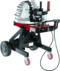
5. The upper urethane roller and support arm (See Figure 4)
is used for bending
1
⁄2" through 1" conduit. One of the
top three shoe grooves will be used, depending on
conduit size.
Frame Stop
Jaw
Bend Groove
Upper Roller
Figure 4. Bending 1/2" - 1"
6. When bending
1
⁄2" - 1" conduit the upper roller and support
arm must be positioned between the shoe and the roller
housing. Position the urethane roller by moving the roller
housing against the frame stop and removing the pin.
7. Lift the roller support arm to clear the nylon rollers and swing
the arm (toward shoe) over the roller housing. Lower the arm
into the support bracket and insert the ring pin. See Figure 5.
Type Scale
Roller Support Arm
Locking Handle
Upper Urethane Roller
EMT Size Scale
Roller Support Arm
Figure 5. Position Roller Support
3
8. Insert the conduit in the shoe groove marked with the number
matching the size conduit being bent. The conduit must set in
the shoe and in the jaw. The end of the conduit must extend
a minimum of 2" beyond the jaw. See Figure 3. Refer to table
A or B on page 5 for bending data.
9. Each time a different size and type of conduit is being bent,
three facts must be determined and set into the bender
shoe control system. The required settings are: conduit size,
material and desired bend angle. Prior to setting, be sure the
desired size indicator scale is toward the operator and the
correct shoe grooves are also toward the operator.
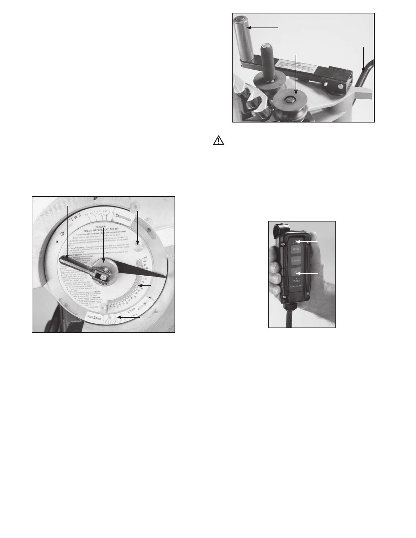
a. Lift the locking handle. See Figure 6. Use the two small
pins to rotate the angle disc, clockwise, until the red zero
line is directly in line with the zero line on the size scale.
b. Set the bender for specific conduit size by turning the
angle disc until the red line is on the size indicator mark
which matches the size conduit being bent. Be sure the
correct size scale is being used (EMT, lMC, or Rigid).
c. Move the bend angle set knob (See Figure 6) until
the flat edge of the pointer is on a line indicating the
exact degree of bend desired. Lower the center arm to
lock the pointer and scale and to prevent inadvertent
movement during bending.
Type Scale
Roller Support Arm
Locking Handle
Upper Urethane Roller
EMT Size Scale
Locking Handle
Angle
Disk
Size Scale
Angle Set Knob
Rotating Pins
Figure 6. Set Angle Scale
10. Activate the bending shoe by holding the pendant control
Bend button. The shoe will rotate until the angle set on the
pointer is reached.
11. To remove the conduit, hold the “Return” button. The shoe
will return to the start position and stop automatically. The
zero set light will come on. Bending more conduit of the
same type and size is accomplished by loading conduit and
pressing the bend button.
4.2 Bending 1
1
⁄4", 1
1
⁄2" and 2" Conduit
NOTE: All operations referring to “toward the operator” are viewed
from the lifting handle end of the bender frame.
1. Bending 1
1
⁄4" through 2" requires using one of the three sets
of nylon rollers and one of the grooves on the lower half of the
bending shoe.
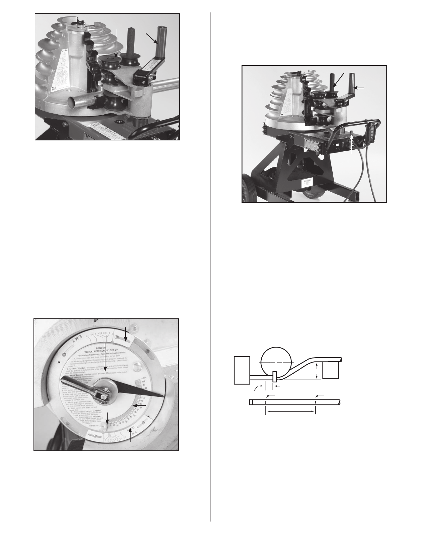
2. Move the roller housing against the frame stop. See Figure
11. The upper urethane roller must be on the outside (toward
frame handle) of the roller housing. See Figure 7. If it’s not,
pull the ring pin. Lift the roller support arm, swing it over the
roller housing, lower the handle into the bracket and insert the
ring pin.
Type Scale
Roller Support Arm
Locking Handle
Upper Urethane Roller
EMT Size Scale
Nylon Rollers
Frame Handle
Upper Urethane Roller
Figure 7. Position Roller Support
CAUTION: To avoid damage to the bending shoe, always
place the roller housing against the frame stop, prior to
activating the bending shoe.
3. Check the bending shoe to be sure the correct grooves for
the conduit being bent are facing toward the operator. If the
shoe must be rotated, hold the pendant control Return button
and press the jog button until the zero light goes out. The
shoe will rotate 180° then stop in the load position. See Figure
8. The zero light will come on.
Zero
Light
Jog
Button
Figure 8. Pendant Control
4. When bending 1
1
⁄4" - 2" conduit, position roller housing and
upper arm. Then push the conduit between the shoe groove
and the 2" nylon rollers until the bend mark on the conduit is
in line with the outside edge of the clamp jaw.
5. Grasp the upper urethane roller and move the support arm
counterclockwise until it contacts the roller housing. The two
nylon rollers should have moved against the conduit and
should firmly hold the conduit in the shoe. See Figure 9.
4
Upper
Urethane
Roller
Nylon
Rollers
Figure 9. Locking in Roller Support
6. Each time a different size and type of conduit is being
bent, three facts must be determined and set into the
bender shoe control system. The required settings
are: conduit size, material and desired bend angle. Prior
to setting, be sure the pipe size scale is toward the
operator and the correct shoe grooves are also toward
the operator.
a. Lift the locking handle to release the angle set knob and
angle disc. Use the two small pins to rotate the angle disc,
clockwise. See Figure 10.
b. Set the bender for specific conduit size by turning the
angle disc until the red line is on an outer size scale mark
which matches the size conduit being bent. See Figure 10.
Be sure the correct size scale is being used (EMT, lMC, or
Rigid).
c. Move the angle set knob (See Figure 10) until the flat edge
of the pointer is on the line indicating the exact degree of
bend desired. Lower the center arm to lock the pointer,
angle disc and to prevent inadvertent movement during
bending.
Type Scale
Roller Support Arm
Locking Handle
Upper Urethane Roller
EMT Size Scale
Zero Point
Rigid/IMC Size Scale
Angle Disc
Angle Set Knob
EMT Size Scale
Figure 10. Set Angle Indicator
7. Use the control pendant. The zero light should be on. Hold
the Bend button. The shoe will rotate until the desired bend is
achieved, then stop automatically.
NOTE: If the zero light is not on, press the Return button until the
shoe stops and the zero light comes on.
8. To unload conduit, hold the Return button. The shoe will return
to the start position and stop automatically.
9. Grasp the upper urethane roller and move the support arm
clockwise until the rollers move away from the conduit. See
Figure 11. Push the roller housing against the frame stop.
Remove bent conduit.
Frame
Stop
Upper
Urethane
Roller
Roller Housing Handle
Figure 11. Unload Conduit
10. To bend more conduit of the same material and at the same
angle, load and secure as described in steps 3 through 6. To
bend the same type conduit but at a different angle, load and
secure; turn angle set knob to the desired angle, then press the
bend button.
11. Bending different type and size conduit requires repeating
steps 2 through 10.
4.3 Offset Bending
1. Obtain distance “M” from table A, and measure this distance
from mark #1 and place mark #2.
2. Now place mark #1 in line with front edge of shoe clamp and
make first bend.
3. Next rotate conduit 180° level, place mark #2 in line with front
edge of shoe clamp and make second bend.
Offset
Beam
Box
M
Front Edge of Clamp
See Ta ble A
Min. 2"
Mark #2Mark #1
NOTE: When bending rigid aluminum, set bend angle indicator
approximately 4° short of desired angle, since aluminum does not
have spring-back of steel.
5
Offset Conduit Conduit Conduit
Required Max. Size M Max. Size M Max. Size M
2"
3
⁄4" 7
3
⁄4"
4" 1
1
⁄2" 15
7
⁄16"
3
⁄4" 8"
6" 2" 23
3
⁄16" 1" 12"
1
⁄2” 8
1
⁄2"
8" 30
5
⁄8" 1
1
⁄2" 16" 1” 11
5
⁄16"
10" 38
5
⁄8" 2" 20" 1
1
⁄4” 14
1
⁄8"
12" 46
3
⁄8" 24" 1
1
⁄2” 16
15
⁄16"
14" 54
1
⁄16" 28" 2" 19
13
⁄16"
16" 61
13
⁄16" 32" 22
5
⁄8"
18" 67
7
⁄16" 36" 25
7
⁄16"
20" 77
1
⁄4" 40" 28
1
⁄4"
22" 85" 44” 31
1
⁄8"
To locate distance between centers of offset bending marks other than
listed in table A use the following multipliers:
15° bend - 3.9
30° bend - 2.0
45° bend - 1.4
Table A
15° Bend 30° Bend 45° Bend
4.4 Stub-up Bending
1. Table C shows minimum length (inches).
2. Mark #1 is stub length, deduct from this as per table C
and obtain mark #2.
Conduit Radius Radius
Size Rigid / IMC EMT
1
⁄2" 3
31
⁄32" 3
7
⁄8"
3
⁄4" 4
25
⁄32" 4
29
⁄32"
1" 5
9
⁄16" 5
29
⁄32"
1
1
⁄4" 6
7
⁄8" 7
3
⁄32"
1
1
⁄2" 7
9
⁄16" 7
1
⁄2"
2" 8
9
⁄32" 8
9
⁄16"
Table B
BEND RADIUS
Shoe
Min. 2"
Stub Length
Set Back
Mark #2
Mark #1
Front Edge of
Clamp Mark #2
Stub to Bottom
of Pipe
1
⁄2" Rigid 7
3
⁄4" 1
1
⁄4" Rigid 12
3
⁄4"
1
⁄2" IMC 7
3
⁄4" 1
1
⁄4" IMC 12
1
⁄2"
1
⁄2" EMT 7
5
⁄8" 1
1
⁄4" EMT 13"
3
⁄4" Rigid 9" 1
1
⁄2" Rigid 13
1
⁄2"
3
⁄4" IMC 9" 1
1
⁄2" IMC 13
1
⁄2"
3
⁄4" EMT 8
1
⁄2" 1
1
⁄2" EMT 13
1
⁄2"
1" Rigid 10
1
⁄8" 2" Rigid 15
3
⁄4"
1" IMC 10
1
⁄8" 2" IMC 15
1
⁄2"
1" EMT 10
3
⁄8" 2" EMT 15
1
⁄2"
Table C
Conduit Stub-up Conduit Stub-up
Size Set-back Size Set-back
5.0 ANGLE ADJUSTMENT
Two different type scales are mounted on the shoe outer rim.
One for
1
⁄2" thru 2" IMC and Rigid, the other for EMT
1
⁄2" thru 2"
See Figure 12.
Each scale indicator is adjustable to compensate for over long
or short bends which may be due to differences in conduit
characteristics or other variations.
Type Scale
Roller Support Arm
Locking Handle
Upper Urethane Roller
EMT Size Scale
Note: Two
scales one
for rigid
and one
for IMC
Type Scale
Type Scale
Figure 12. Two Type Scales
Bends which are too long: Loosen the size scale (for type material
being bent) mounting screws. Slide the scale clockwise as many
degrees as the overbend (if bend is 5° over, move indicator 5°
clockwise). The degree of movement is observed by watching one
of the size marks as it moves past the angle disc scale. Tighten
the mounting screws.
Bends which are too short: Loosen the size scale (for type material
being bent) mounting screws. Slide the scale counterclockwise
as many degrees as the bend is short (if bend is 5° short move
counterclockwise 5°). The degree movement is observed by watching
one of the size marks as it moves past the angle disc scale. Tighten
the mounting screws.
6
7
6.0 MAINTENANCE
Periodic general maintenance to the bender may be required to
reduce the risk of malfunctioning rollers, sprockets, gear teeth,
and/or chains. These parts can become dirty, worn, or damaged
over time and may need to be greased or cleaned. Pressurized
air can be used to clean any dust or residue inside the bender
housing. The bender should not make any uncommon noises such
as rattling during use. If this happens, turn off the bender and
perform an inspection on the machine.
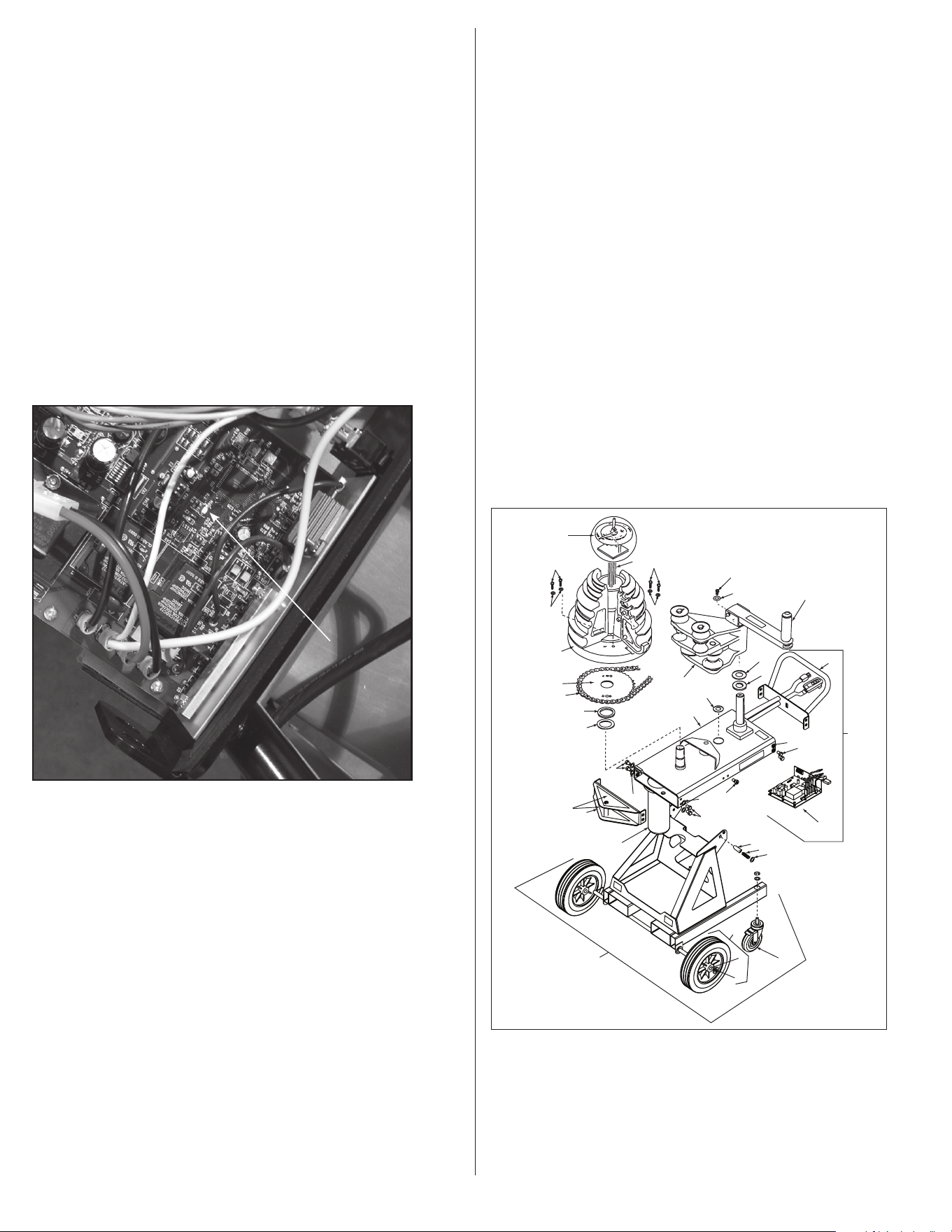
A troubleshooting aid exists on the printed circuit board mounted
to the inside of the operating handle. If all systems are functional,
a white L.E.D. (pictured in Figure 13) will flash once every two
seconds while the machine is powered up.
Error codes consist of different light patterns.
1. Blink twice = the motor is over heated.
2. Blink three times = limit switch has failed.
3. Blink 4 times = pendant control malfunction.
In addition the L.E.D. will be steady on if the bend or return button
is being pressed.
White L.E.D.
Figure 13. L.E.D. Location
7.0 TRANSPORTATION
7.1 On ground Transportation
1. Rotate bender to the horizontal bending position.
a. Pull handle end of the bender to remove the preload
applied on the locking pin of the bender (Figure 14, #14),
and pull positioning pin.
b. While pulling positioning pin, carefully raise the handle end
of the bender until the sprocket housing (Figure 14, #4)
locks in the horizontal position.
2. Unlock wheels (if locked) (Figure 14, #13), and use handle
(Figure 14, #38) to push/pull bender to the desired location.
7.2 Forklift Transportation
1. Rotate bender to the horizontal bending position.
a. Pull handle end of the bender to remove the preload applied
on the positioning pin of the bender (Figure 14, #14), and
pull locking pin.
b. While pulling positioning pin, carefully raise the handle end
of the bender until the sprocket housing (Figure 14, #4)
locks in the horizontal position.
2. From the back of the bender opposite to the handle, insert forks
into fork tubes. Refer to decals located on frame for detailed
instructions.
3. Move to the desired location.
7.3 Lift/Hoist Transportation
1. If nylon sling is being used, ensure sling is long enough to
avoid contact with the bender. Bender should be hoisted in the
vertical bending position only.
2. Confirm that the Roller Housing (Figure 14, #20) and Upper
Roller (Figure 14, #12) are in place and locked.
3. Loop the nylon sling through the End Plate Lift Hook
(Figure 14, #26). DO NOT HOIST BENDER USING THE HANDLE
(Figure 14, #38).
4. NOTE: End Plate Lift Hook can also be used for job site tethering
for added security.
23
24
12
38
20
36
21
34
35
13
19
21
22
17
15
16
14
SEE INSERT A Page 3
& Fig. 6, (page 8)
4
27
34
34
37
35
35
18
(See Fig. 7)
3
Figure 1
B2000 Bender Assembly
2
9
10
9
10
1
7
8
5
6
26
11
25
Figure 14. Bender Transportation

8
RPS_0097_0717
800.822.9220 • Milwaukee, WI 53209 • gardnerbender.com
GARDNER BENDER LIMITED WARRANTY: Gardner Bender warrants its product against defects in workmanship and materials for 1 year from date of
delivery to user. Chain is not warranted. Warranty does not cover ordinary wear and tear, abuse, misuse, overloading, altered products or use of improper
fluid.
LIMITED: Limited means that GB warrants to the original purchasers of products from GB authorized distributors at the time of shipment such products
shall be free of defects in material and workmanship while the tool is used under normal working conditions. Standard wear and tear, dulling over time,
overloading, misuse, and acts of God are not covered under warranty. This warranty does not cover batteries, fuses,
or test leads.
When a warranty claim arises, the purchaser must contact GB. If the defect comes under the terms of this limited warranty,
GB will arrange, at its sole discretion, one of the following options:
• The product will be repaired at an authorized GB Service Center
• Product will be replaced
The purchaser is solely responsible for determining the suitability of GB for the purchaser’s use or resale, or for incorporating them into articles or using
them in the purchaser’s applications. The distributor is authorized to extend the foregoing limited warranty to its original purchasers in connection with the
sales of GB products, provided that such products shall not have been altered by the distributor. The distributor shall be fully responsible for any warranties
the distributor makes to its purchasers which are broader or more extensive than GB limited warranty.
LIFETIME WARRANTY
Warranty Limitation: The forgoing warranties are exclusive and are in lieu of all other express and implied warranties whatsoever, including but not limited to
implied warranties of merchantability and fitness for a particular purpose. The foregoing warranties do not cover ordinary wear and tear, abuse, misuse,
overloading, alterations, products which have not been installed, operated or maintained in accordance with GB written instructions. Test leads, fuses, and
batteries are not covered under any implied warranty. “Lifetime” of products that are no longer offered by GB will be either repaired or replaced with an item
of GB Instruments choice of similar value. Lifetime is defined as 5 years after GB discontinued manufacturing the product, but the warranty period shall be
at least ten years from date of purchase. Original proof of purchase is required to establish original ownership of product.
No warranty will be honored unless an invoice or other proof of purchase date is provided to Gardner Bender.
Hand written receipts or invoices will not be honored.
©2016 Product Power, LLC All rights reserved. - See more at: http://www.gardnerbender.com/en/resources/warranty-page#sthash.5Y2dIBQV.dpuf