Loading ...
Loading ...
Loading ...
6
Bend function works,
return function results
in bending direction.
Direction circuit on P.C.
board is malfunctioning.
Replace P.C. board.
Refer to “Circuit Board” in “DISASSEMBLY” section (page 7) for instructions.
Return function works,
bend function results in
shoe moving in return
direction.
Brake circuit on P.C.
board is malfunctioning.
If all other tests are positive, replace P.C. board.
Refer to “Circuit Board” in “DISASSEMBLY” section (page 7) for instructions.
Return function works.
Depressing bend
switch, shoe moves
in return.
Direction circuit on P.C.
board is malfunctioning.
Replace P.C. board.
Refer to “Circuit Board” in “DISASSEMBLY” section (page 7) for instructions.
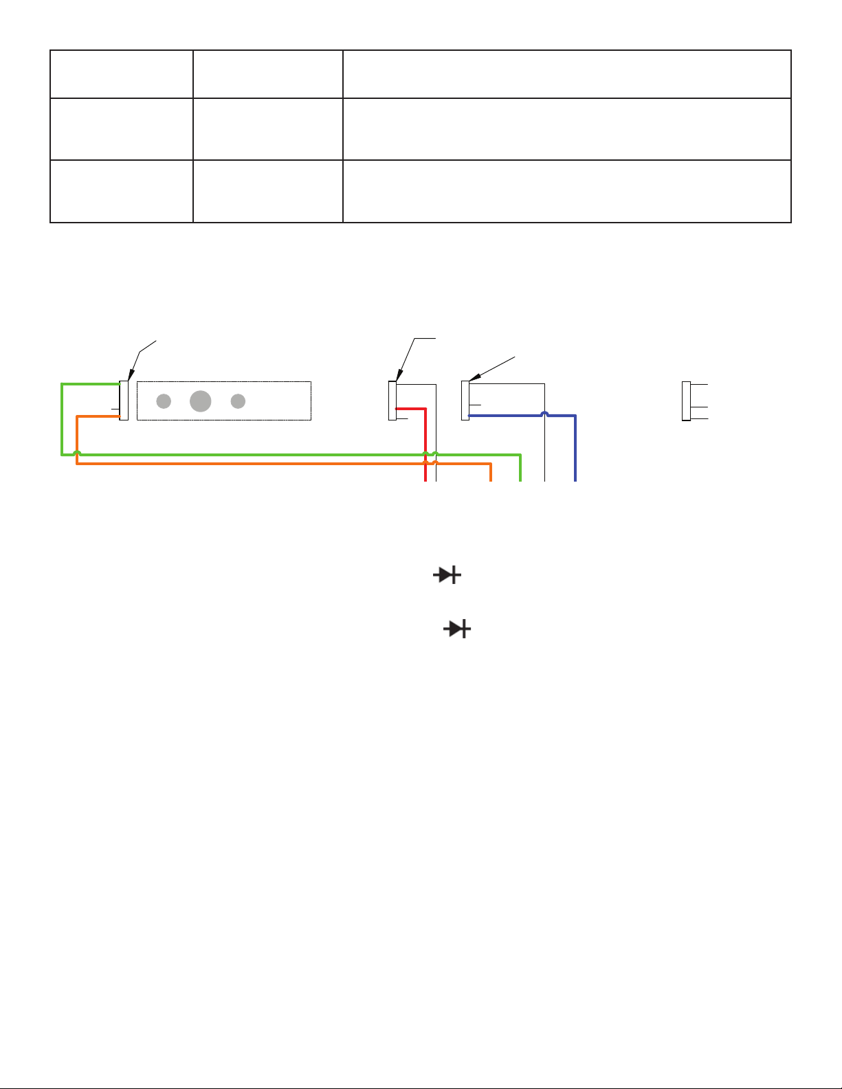
2.0 PENDANT (P05C) TROUBLESHOOTING
1. Verify continuity for both wires traveling from the zero limit switch down to the wire harness.
2. Verify that the black wire goes to the pin on the limit switch that is separate from the other two, and that the red wire
is connected to the middle pin.
3. Test Zero Light - Take a multimeter and set it to the diode (
) function and place the red lead on the orange wire
in the harness and the black lead to the red (pink) wire in the harness. This should illuminate the green Zero LED
4. Test Power LED - Take a multimeter and set it to the diode (
) function and place the red lead on the orange wire
and black lead on the yellow wire. This should illuminate the red Power LED.
5. Test Bend Button - Set a multimeter to the continuity or ohms function. Place one meter lead to the pin of the Black
wire in the pendant wire harness, and place the other lead on the pin for the Blue with Black strip wire. While the
probe tips are making contact with the pins in the harness, press the bend button. When the button is pressed, 0
Ohms and/or the continuity buzzer should go off.
6. Test Return Button - Set a multimeter to continuity or ohms function. Place one meter lead on the pin of the Black
wire in the pendant wire harness. Place the other meter lead to the pin of the Blue wire in the harness. With the
probes still making contact with the pins, press the Return button. When the button is pressed, 0 Ohms and/or the
continuity buzzer should go off.
7. Test Jog Button - Set a multimeter to the continuity or Ohms function. Place one meter lead to the pin of the Black
wire in the pendant wire harness, and place the other lead on the pin for the Brown wire. While the probe tips are
making contact with the pins in the harness, press the bend button. When the button is pressed, 0 Ohms and/or the
continuity buzzer should go off.
WHITE
ORANGE GREEN
RED
BLACK
BLUE
YELLOW
GREY
(43)
(42)
(41)
(46)
(45)
(44)
(48)
(47)
(OPEN)
RED
BLUE
(OPEN)
WHITE
ORANGE
(OPEN)
GREEN
GREY
YELLOW
RED
BLACK
FEMALE CONNECTOR
MALE CONNECTOR
BEND LIMIT SWITCH
ZERO STOP SWITCH
P8
P7
P5
P6
RED
BLACK
BLACK
RED
POWER CORD
FEMALE CONNECTOR
MALE CONNECTOR
WHITE
BLACK
BLACK
BLACK
BLACK
WHITE
WHITE
WHITE
WHITE
BLACK
CIRCUIT BOARD
BLACK
RETURN LIMIT SWITCH Typical Switch Contacts
BLOCK MOUNTING
CONNECTOR TO CIRUIT BOARD
AZ
BLAC
K
BMK3 SWITCH
NORMALLY CLOSED
NORMALLY OPEN
COMMON
BOTTOM OF MOTOR
NOTE: 2-LONG STUDS FOR COVER MOUNTING ONLY
Wiring Schematic
Loading ...
Loading ...
Loading ...