Loading ...
Loading ...
Loading ...
maintenance
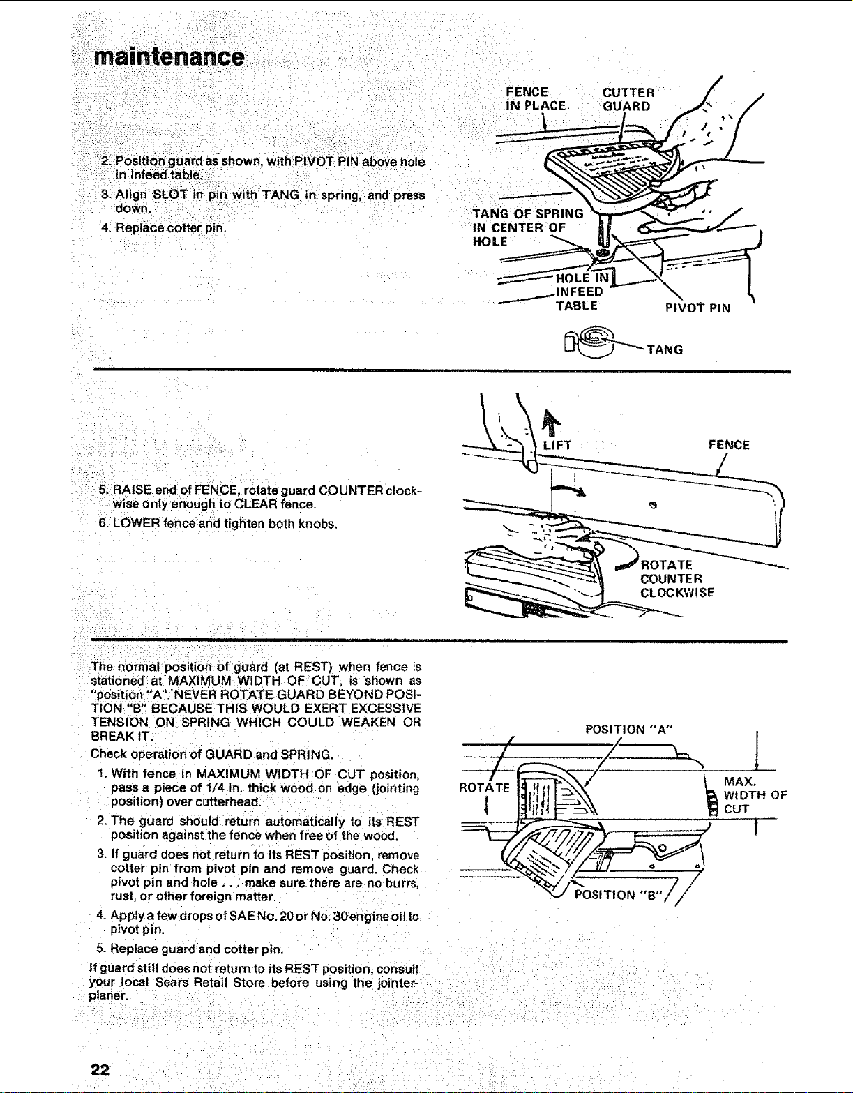
2. Position guard as shown with;PIVOT PIN above hole
in infeedtable.
3, Align SLOT in pin With TANG in spring, and press
down.
4i Replace cotter pin.
FENCE
IN PLACE
TANG OF SPRING
IN CENTER OF
HOLE
CUTTER
GUARD
'1 iii ii i
PIVOT PIN
5. RAISE end of FENCE, rotate guard COUNTER clock-
wise only enough to CLEAR fence,
6. LOWER fence and tighten both knobs.
\
LI FT
COUNTER
CLOCKWISE
FENCE
= =
The normal position of guard (at REST) when fence is
stationed at MAXIMUM WIDTH OF CUT. is shown as
"position "A". NEVER ROTATE GUARD BEYOND POSI-
TION "B" BECAUSE THIS WOULD EXERT EXCESSIVE
TENSION ON SPRING WHICH COULD WEAKEN OR
BREAK IT.
Check operation of GUARD and SPRING.
1. With fence in MAXIMUM WIDTH OF CUT position,
pass a piece of 1/4 in, thick wood on edge (jointing
position) over cutterhead.
2. The guard should return automatically to its REST
position against the fence when free of the wood.
3. If guard does not return to its REST position, remove
cotter pin from pivot pin and remove guard. Check
pivot pin and hole.., make sure there are no burrs,
rust, or other foreign matter.
4. Apply a few drops of SAE No. 20 or No, 3Oengine oil to
pivot pin.
5. Replace guard and cotter pin.
POSIT1ON °'B"i,J /
If guard still does not return to its REST position consult
your local Sears Retail Store before using the jointer- :
planer.
[
MAX.
WIDTH OF
CUT
!
22 - i:
Loading ...
Loading ...
Loading ...