
Loading ...
Loading ...
Loading ...
6
Unpacking
Carton Contents:
• Cordless snow blower with handle frame
• Discharge chute assembly
• Discharge chute screws (x3)
• Hex key
• Manual with registration card
NOTE: In order to operate this cordless snow blower you will
need 24V iON+ System batteries and chargers. See page 17 for
battery options and specifications, or visit snowjoe.com.
1. Carefully remove the cordless snow blower and check to
see that all of the above items are supplied.
2. Inspect the product carefully to make sure no breakage or
damage occurred during shipping. If you find damaged or
missing parts, DO NOT return the unit to the store. Please
call the Snow Joe
®
+ Sun Joe
®
customer service center at
1‑866‑SNOWJOE (1‑866‑766‑9563).
3. NOTE: Do not discard the shipping carton and packaging
material until you are ready to use the cordless snow
blower. The packaging is made of recyclable materials.
Properly dispose of these materials in accordance with
local regulations or save the packaging for long‑term
product storage.
IMPORTANT! The equipment and packaging material are
not toys. Do not let children play with plastic bags, foils or small
parts. These items can be swallowed and pose a suffocation
risk!
Assembly
mWARNING! To avoid serious personal injury, read and
understand all safety instructions provided.
mWARNING! Unpacking and assembly should be
completed on a flat and stable surface, with adequate space for
moving the machine and its packaging.
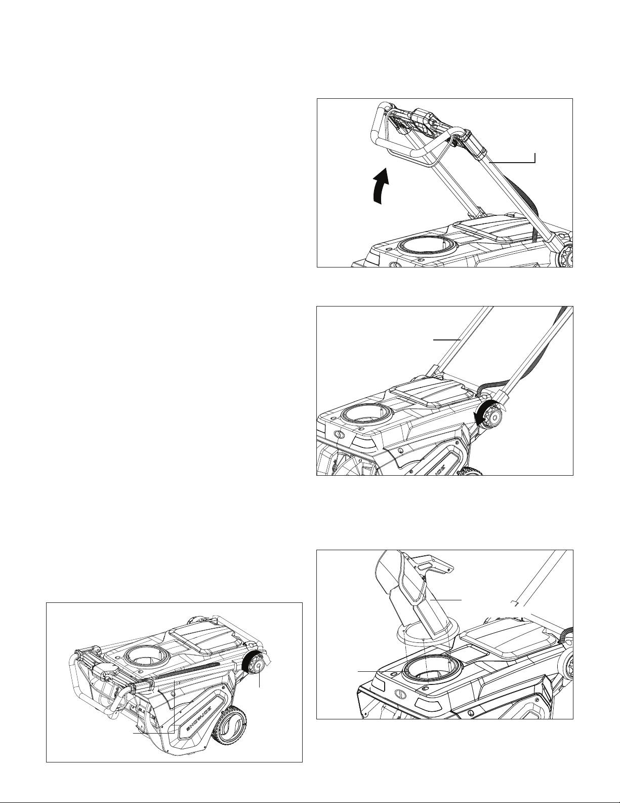
Adjusting the Handle Frame
1. Unlock the handle frame by rotating the handle frame locks
on both sides clockwise (Fig. 1).
Handle frame
Handle
frame lock
Fig. 1
2. Rotate the handle frame up in a comfortable operation
position (Fig. 2).
3. Lock the handle frame in position by rotating the handle
frame locks on both sides counter‑clockwise (Fig. 3).
Discharge Chute Assembly
1. Place the discharge chute assembly onto the gear plate,
aligning the 3 holes in the gear plate, and push down until
the chute is flush and flat against the housing (Fig. 4).
Handle frame
Fig. 2
Handle frame
Rotate to lock
Fig. 3
Discharge
chute assembly
Gear
plate
Fig. 4
Loading ...
Loading ...
Loading ...