Loading ...
Loading ...
Loading ...
After assembling all three chute flange keepers,
tighten, then back off 1/4 turn to allow easier
movement of the chute. Use two 7/16" wrenches.
AttachingChuteDirectionalControl
(Hardware Group D)
• Thread one hex nut about halfway onto eye bolt on
the chute directional control.
• Insert eye bolt through the hole provided in the left
handle. See Figure 6.
• Secure with cupped washer (cupped side against
the handle) and other hex nut. Do not tighten until
after attaching the other end of the chute directional
control.
Hairpin
Clip_
\
Flat
Washers
Chute
Directional
Control
_Lower Chute
Bracket
Eye Bolt
Figure 6
To align the spiral on the chute directional control,
you may have to loosen the carriage bolts and hex
lock nuts securing lower chute bracket to the
extension on the left side of the chute assembly.
See Figure 7.
Carriage
Bolts
Lower Chute f
Bracket
Hex Lock
Nuts
Figure 7
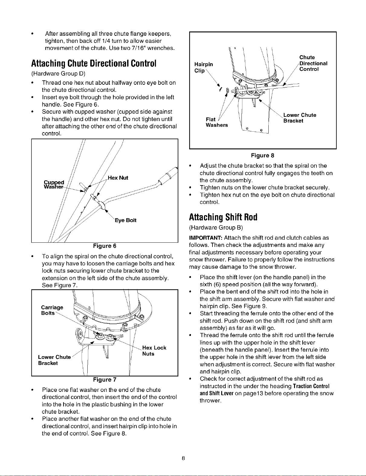
• Place one flat washer on the end of the chute
directional control, then insertthe end of the control
into the hole in the plastic bushing in the lower
chute bracket.
• Place another flat washer on the end of the chute
directional control, and insert hairpin clip into hole in
the end of control. See Figure 8.
Figure 8
• Adjust the chute bracket so that the spiral on the
chute directional control fully engages the teeth on
the chute assembly.
• Tighten nuts on the lower chute bracket securely.
• Tighten hex nut on the eye bolt on chute directional
control.
AttachingShiftRod
(Hardware Group B)
IMPORTANT:Attach the shift rod and clutch cables as
follows. Then check the adjustments and make any
final adjustments necessary before operating your
snow thrower. Failure to properly follow the instructions
may cause damage to the snow thrower.
• Place the shift lever (on the handle panel) in the
sixth (6) speed position (all the way forward).
• Place the bent end of the shift rod into the hole in
the shift arm assembly. Secure with flat washer and
hairpin clip. See Figure 9.
• Start threading the ferrule onto the other end of the
shift rod. Push down on the shift red (and shift arm
assembly) as far as it will go.
• Thread the ferrule onto the shift red until the ferrule
lines up with the upper hole in the shift lever
(beneath the handle panel). Insert the ferrule into
the upper hole in the shift lever from the left side
when adjustment is correct. Secure with flat washer
and hairpin clip.
• Check for correct adjustment of the shift red as
instructed in the under the heading TractionCentral
andShiftLeveron page 13 before operating the snow
thrower.
Loading ...
Loading ...
Loading ...