Loading ...
Loading ...
Loading ...
1. Disconnect power.
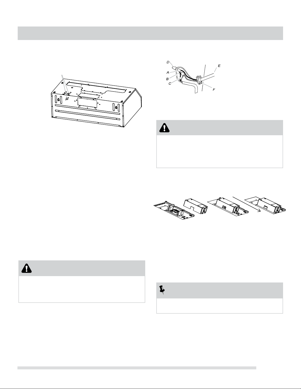
2. Use UL listed wire connectors and connect white wires
(A) together.
3. Use UL listed wire connectors and connect black wires
(B) together.
WARNING
Fire Hazard
Electrically ground the blower. Use copper wire.
Connect ground wire to green wire in
terminal box. Failure to do so can result in death,
re, or electrical shock.
4. Connect green (or bare) ground wire from power supply
to green wire in terminal box .
5. Install terminal box cover.
Complete Installation
grease lters . See the “Range Hood
Check the operation of the range hood fan and light.
See “Range Hood Use” section.
If range hood does not operate, check to see whether a
circuit breaker has tripped or a household fuse has blown.
Disconnect power and check wiring connections.
NOTE
To get the most efcient use from your new
range hood, read the “Range Hood Use” section.
Remove the power supply knockout from the top
or rear of the vent hood (depending on the incoming
location of your home power supply cable) and
install a UL listed or CSA approved ½” strain relief.
Feed enough electrical wire through the ½” UL listed
or CSA approved strain relief to make connections in
the terminal box. Tighten the strain relief screws.
Position the range hood so that the large end of
the keyhole slots are over the mounting screws.
Then push the hood toward the wall so that the screws
are in the neck of the slots. Tighten the mounting screws,
making sure the screws are in the narrow neck of slots.
Connect ventwork to hood. Seal joints with vent
clamps or duct tape to make secure and airtight.
Check that back draft dampers work properly.
MAKE ELECTRICAL CONNECTION
WARNING
Electrical Shock Hazard
Disconnect power before servicing.
Replace all parts and panels before operating.
Failure to do so can result in death or electrical shock.
3.
4.
5.
INSTALLING THE HOOD
Use” section.
1.
2.
6. Reconnect power.
Lift the hood into nal position.
1
A. White wires
B. Black wires
C. Green ground wire
D. UL listed wire connector
E. Home power supply cable
F. UL listed or CSA approved
½” strain relief
Add the 2 rear 0.49 * 5.0 cm rear mounting screws
into the narrow neck of the rear keyhole slots.
These should screw into the horizontal support
that was placed between the two wall studs in
section PREPARE THE LOCATION on page 8.
6.
7.
8.
Install
EN-1
A. Power supply
knockout
A
Loading ...
Loading ...
Loading ...