Loading ...
Loading ...
Loading ...
]i!ill
FLEXIBLE PUMP COUPLER
Theflexible pumpcoupleris a nylon"spider"insert,locatedbetween
the pumpandthe engineshaft.Overtime,the couplerwillhardenand
deteriorate.
Replacethecouplerif you detectvibrationor noisecomingfromthe
areabetweenthe engineand the pump.If thecouplerfailscompletely,
youwill experiencea lossof power.
iMPORTANT:Neverhit the engineshaftin any manner,as a blowwill
causepermanentdamageto the engine.
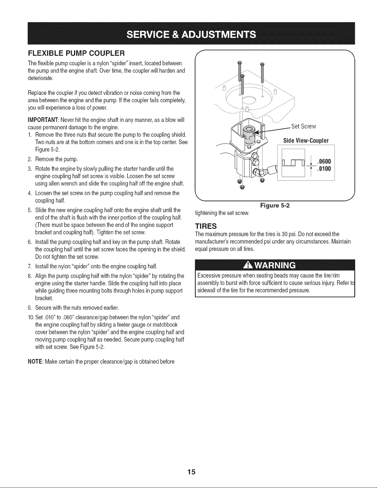
1. Removethethree nutsthat securethe pumpto the couplingshield.
Twonutsareat the bottomcornersandoneis inthe top center.See
Figure5-2.
2. Removethepump.
3. Rotatethe engineby slowlypullingthe starterhandleuntilthe
enginecouplinghalf set screwis visible.Loosenthe set screw
usingallen wrenchand slidethe couplinghalfoff the engineshaft.
4. Loosenthe setscrewonthe pumpcouplinghalf andremovethe
couplinghalf.
5. Slide thenewengine couplinghalf ontotheengine shaftuntil the
endof the shaftis flush with the innerportionof the couplinghalf.
(Theremustbe space betweenthe endof the enginesupport
bracketandcouplinghalf).Tightenthe set screw.
6. Installthe pumpcouplinghalfand key on thepump shaft.Rotate
the couplinghalf untilthe set screwfaces theopeningin the shield.
Do nottightenthe set screw.
7. Installthe nylon"spider"ontothe enginecouplinghalf.
8. Align thepumpcouplinghalfwiththe nylon"spider"by rotatingthe
engineusingthe starterhandle.Slidethecouplinghalfinto place
whileguidingthreemountingbolts throughholesin pumpsupport
bracket.
9. Securewith the nutsremovedearlier.
10.Set .010"to .060"clearance/gapbetweenthe nylon"spider"and
the enginecouplinghalf byslidinga feelergaugeor matchbook
coverbetweenthenylon"spider"andthe enginecouplinghalf and
movingpumpcouplinghalfas needed.Securepumpcouplinghalf
withsetscrew.SeeFigure5-2.
/
Screw
Side View-Coupler
; .oooo
.0100
Figure 5=2
tighteningthe set screw.
J
TIRES
The maximumpressurefor the tires is 30 psi.Do notexceedthe
manufacturer'srecommendedpsi underany circumstances.Maintain
equalpressureonall tires.
Excessivepressurewhenseatingbeadsmaycausethe tire/rim
assemblyto burstwithforcesufficientto cause seriousinjury. Refertc
sidewallof the tirefor the recommendedpressure.
NOTE:Makecertainthe properclearance/gapis obtainedbefore
15
Loading ...
Loading ...
Loading ...