
Operator's Manual
CRRFrSM ®
675 Series
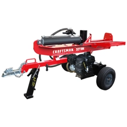
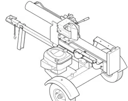
LOG SPLITTER
Model No. 247.77640
CAUTION: Before using
this product, read this
manual and follow all
safety rules and operating
instructions.
o SAFETY
ASSEMBLY
OPERATION
MAINTENANCE
PARTS LIST
Spanish
Sears, Roebuck and Co., Hoffman Estates, IL 60179, U.S.A.
Visit our web site: www.sears.com/craftsman FORMNO.769-03989A
2/4/2009

WarrantyStatement..................................Pac
RepairProtectionAgreement...................Pac
SafeOperationPractices..........................Pac
SafetyLabels............................................Pac
Assembly..................................................Pac
Operation..................................................Pac
Service&Adjustments.............................Pac
e2
e3
es4-6
e7
es8-9
es10-13
es14-15
Maintenance.............................................Pages16-18
OffSeasonStorage..................................Page19
Troubleshooting........................................Page20-22
PartsList...................................................Page24-31
Espa_ol.....................................................Page34
ServiceNumbers......................................BackCover
Limited Warranty on Craftsman Log Splitter
Forone(1)yearfromthe dateof purchase,ifthisCraftsmanEquipmentismaintained,lubricated,andtuned up accordingto the instructionsto
theoperator'smanual,Searswill repairor replacefreeof chargeany partsfoundto be defectivein materMor workmanship.Warrantyserviceis
availablefreeof chargeby returningCraftsmanequipmentto yournearestSearsServiceCenter.In-homewarrantyserviceisavailablebut a trip
chargewill apply.This Warrantyappliesonly whilethisproductis inthe UnitedStates.
This warranty does not cover:
• Expendableitemswhichbecomewornduringnormaluse,suchas sparkplugs, air cleaners,belts,and oil filters.
• Tire replacementor repaircausedby puncturesfrom outsideobjects,such as nails,thorns,stumps,or glass.
• Repairsnecessarybecauseof operatorabuse,includingbutnot limitedto, damagecausedbyobjects,suchas stonesor metaldebris,
oversizedstock,impactingobjectsthat bendthe frameor crankshaft,orover-speedingtheengine.
• Repairsnecessarybecauseof operatornegligence,includingbut not limitedto, electricaland mechanicaldamagecausedby improper
storage,failureto usethe propergradeandamountof engineoil, or failureto maintainthe equipmentaccordingto the instructionscontained
inthe operator'smanual.
• Engine(fuelsystem)cleaningor repairscausedbyfuel determineto be contaminatedor oxidized(stale). Ingeneral,fuelshouldbe used
within30 daysof itspurchasedate.
• Equipmentusedforcommercialor rentalpurposes.
WARRANTYSERVICEIS AVAILABLEBYRETURNINGTHECRAFTSMANSNOWTHROWERTOTHE NEAREST
SEARSPARTS& REPAIRCENTERINTHEUNITEDSTATES.
Thiswarrantyappliesonly whilethis productis in use inthe UnitedStates.
TO LOCATETHE NEARESTSEARSPARTS& REPAIRCENTEROR TOSCHEDULESERVICE,
SIMPLYCONTACTSEARSAT 1-800-4-MY-HOME®.
Thiswarrantygivesyou specificlegal rightsand youmayalso haveotherrights whichmay vary from stateto state.
SEARS,ROEBUCKANDCO., D/817WA,HOFFMANESTATES,IL 60179
Engine Series: 126T02-0523
Engine Oil: SAE 30
Engine Oil Capacity: 20 Ounces
Fuel Capacity: 1.5 Quarts
Spark Plug (.030" Gap): Champion® RJ19LM
Hydraulic Fluid/Capacity: Dexron® Ill/3.0 gal.
Model Number .............................................................
Serial Number ..............................................................
Date of Purchase ..........................................................
Record the model number, serial number
and date of purchase above
2
Congratulationson makinga smartpurchase.YournewCraftsman@
productis designedand manufacturedfor yearsof dependableopera-
tion.But likeall products,it may requirerepairfrom time to time.That's
whenhavinga RepairProtectionAgreementcansave youmoneyand
aggravation.
Here'swhatthe RepairProtectionAgreement*includes:
* Expert service byour 10,000professionalrepairspecialists
o Unlimitedserviceand no chargefor partsand laboron all
coveredrepairs
o Product replacementupto $1500if yourcoveredproductcan't be
fixed
• Discountof 10%from regularprice of serviceand relatedinstalled
partsnotcoveredby theagreement;also,10%off regularpriceof
preventivemaintenancecheck
• Fast help by phone- we call it RapidResolution- phone support
froma Searsrepresentative.Thinkof usas a "talkingowner's
manual."
Onceyou purchasethe Agreement,a simplephonecall is all thatit
takesfor youto scheduleservice.Youcan call anytimedayor night,or
schedulea serviceappointmentonline.
The RepairProtectionAgreementis a risk-freepurchase.If youcancel
for any reasonduringthe productwarrantyperiod,wewill provideafull
refund.Or,a proratedrefundanytimeafterthe productwarrantyperiod
expires.Purchaseyour RepairProtectionAgreementtoday!
Somelimitationsand exclusionsapply. For pricesand additional
informationin the U.S.A.call 1-800-827-6655.
*Coverage in Canadavaries on some items.Forfull details call
Sears Canadaat 1-800-361-6665.
Sears Installation Service
ForSearsprofessionalinstallationof homeappliances,garagedoor
openers,waterheaters,andothermajorhomeitems,in the U.S.A.or
Canadacall 1-800-4-MY-HOME®.
3
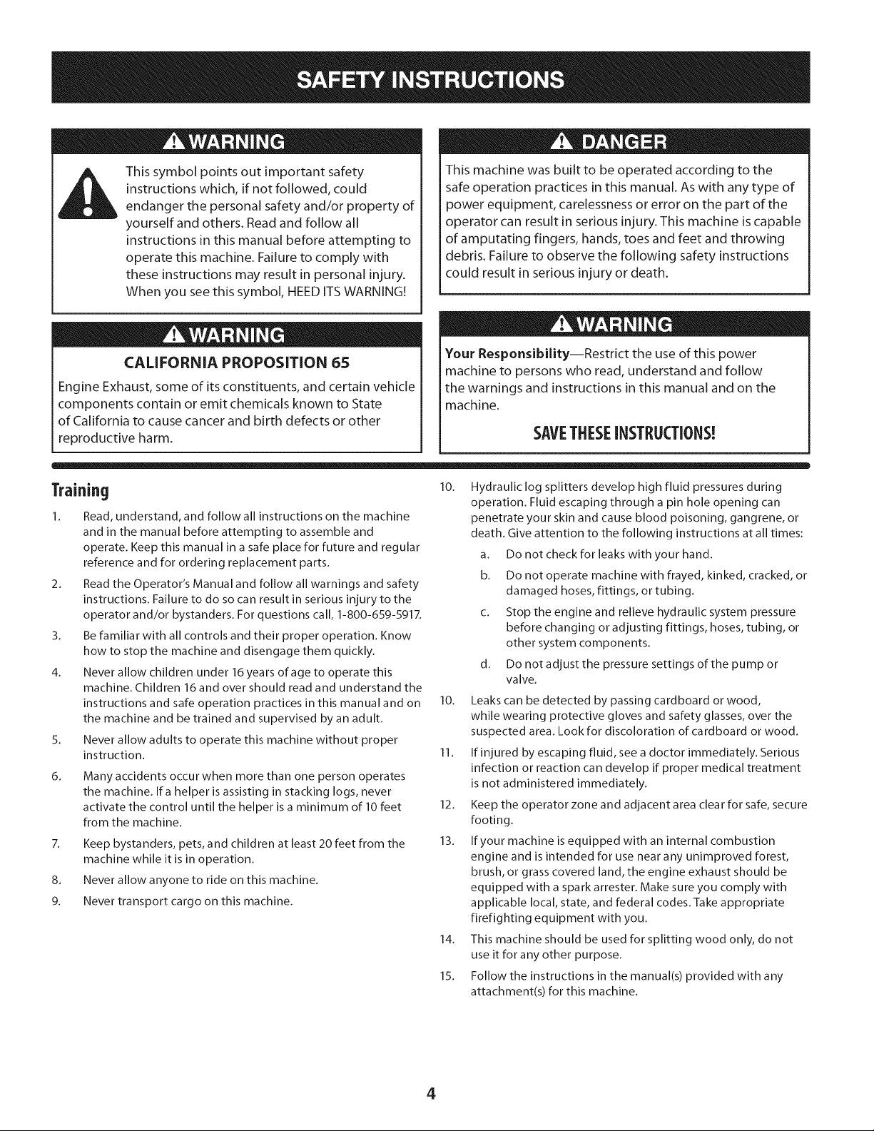
This symbol points out important safety
instructions which, if not followed, could
endanger the personal safety and/or property of
yourself and others. Read and follow all
instructions in this manual before attempting to
operate this machine. Failure to comply with
these instructions may result in personal injury.
When you see this symbol, HEED ITS WARNING!
CALIFORNIA PROPOSITION 65
Engine Exhaust, some of its constituents, and certain vehicle
components contain or emit chemicals known to State
of California to cause cancer and birth defects or other
reproductive harm.
This machine was built to be operated according to the
safe operation practices in this manual. As with any type of
power equipment, carelessness or error on the part of the
operator can result in serious injury. This machine is capable
of amputating fingers, hands, toes and feet and throwing
debris. Failure to observe the following safety instructions
could result in serious injury or death.
Your Responsibility--Restrict the use of this power
machine to persons who read, understand and follow
the warnings and instructions in this manual and on the
machine.
SAVETHESEINSTRUCTIONS!
Training lO.
1. Read, understand, and follow all instructions on the machine
and in the manual before attempting to assemble and
operate. Keep this manual in a safe place for future and regular
reference and for ordering replacement parts.
2. Read the Operator's Manual and follow all warnings and safety
instructions. Failure to do so can result in serious injury to the
operator and/or bystanders. For questions call, 1-800-659-5917.
3. Be familiar with all controls and their proper operation. Know
how to stop the machine and disengage them quickly.
4. Never allow children under 16 years of age to operate this
machine. Children 16 and over should read and understand the
instructions and safe operation practices in this manual and on
the machine and be trained and supervised by an adult.
5. Never allow adults to operate this machine without proper
instruction.
6.
Many accidents occur when more than one person operates
the machine. Ira helper is assisting in stacking logs, never
activate the control until the helper is a minimum of 10 feet
from the machine.
7. Keep bystanders, pets, and child ren at least 20 feet from the
machine while it is in operation.
8. Never allow anyone to ride on this machine.
9. Never transport cargo on this machine.
Hydraulic log splitters develop high fluid pressures during
operation. Fluid escaping through a pin hole opening can
penetrate your skin and cause blood poisoning, gangrene, or
death. Give attention to the following instructions at all times:
a. Do not check for leaks with your hand.
b. Do not operate machine with frayed, kinked, cracked, or
damaged hoses, fittings, or tubing.
c. Stop the engine and relieve hydraulic system pressure
before changing or adjusting fittings, hoses, tubing, or
other system components.
d. Do not adjust the pressure settings of the pump or
valve.
10. Leaks can be detected by passing cardboard or wood,
while wearing protective gloves and safety glasses, over the
suspected area. Look for discoloration of cardboard or wood.
11. If injured by escaping fluid, see a doctor immediately. Serious
infection or reaction can develop if proper medical treatment
is not administered immediately.
12. Keep the operator zone and adjacent area clear for safe, secure
footing.
13. If your machine is equipped with an internal combustion
engine and is intended for use near any unimproved forest,
brush, or grass covered land, the engine exhaust should be
equipped with a spark arrester. Make sure you comply with
applicable local, state, and federal codes. Take appropriate
firefighting equipment with you.
14. This machine should be used for splitting wood only, do not
use it for any other purpose.
15. Follow the instructions in the manual(s) provided with any
attachment(s) for this machine.
4
Preparation Operation
1. Always wear safety shoes or heavy boots.
2. Always wear safety glasses or safety goggles when operating
this machine.
3. Never wear jewelry or loose clothing that might become
entangled in moving or rotating parts of the machine.
4. Make sure machine is on a level surface before operating.
5. Always block wheels to prevent unintended movement, and
lock beam in either the horizontal or vertical position.
6. Always operate this machine from the operator zone(s)
specified in the manual.
7. Logs should be cut with square ends prior to splitting.
8. Use log splitter in daylight or under good artificial light.
SafeHandling of Gasoline
To avoid personal injury or property damage use extreme care in
handling gasoline. Gasoline is extremely flammable and the vapors
are explosive. Serious personal injury can occur when gasoline is
spilled on yourself or your clothes which can ignite. Wash your skin
and change clothes immediately.
a. Use only an approved gasoline container.
b. Extinguish all cigarettes, cigars, pipes, and other sources
of ignition.
c. Never fuel machine indoors.
d. Never remove gas cap or add fuel while the engine is
hot or running.
e. Allow engine to cool at least two minutes before
refueling.
fl Never overfill the fuel tank. Fill tank to no more than 1/2
inch below bottom of filler neck to provide space for
fuel expansion.
g. Replace gasoline cap and tighten securely.
h. If gasoline is spilled, wipe it off the engine and
equipment and move machine to another area. Wait five
(5) minutes before starting the engine.
i. Never store the machine or fuel container inside where
there is an open flame, spark or pilot light as on a water
heater, space heater, furnace, clothes dryer or other gas
appliances.
j. Allow machine to cool at least five (5) minutes before
storing.
1. Before starting this machine, review the "Safety Instructions".
Failure to follow these rules may result in serious injury to the
operator or bystanders.
2. Never leave this machine unattended with the engine running.
3. Do not operate machine while under the influence of alcohol,
drugs, or medication.
4. Never allow anyone to operate this machine without proper
instruction.
5.
Always operate this machine with all safety equipment in place
and working. Make sure all controls are properly adjusted for
safe operation.
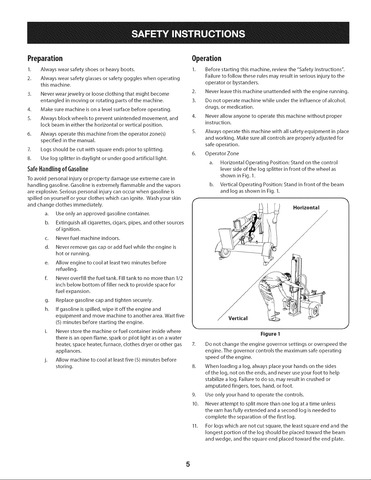
Operator Zone
a. Horizontal Operating Position: Stand on the control
lever side of the log splitter in front of the wheel as
shown in Fig. 1.
b. Vertical Operating Position: Stand in front of the beam
and log as shown in Fig. 1.
Horizontal
Vertical
Figure 1
7. Do not change the engine governor settings or overspeed the
engine. The governor controls the maximum safe operating
speed of the engine.
8. When loading a log, always place your hands on the sides
of the log, not on the ends, and never use your foot to help
stabilize a log. Failure to do so, may result in crushed or
amputated fingers, toes, hand, or foot.
9. Use only your hand to operate the controls.
10. Never attempt to split more than one log at a time unless
the ram has fully extended and a second log is needed to
complete the separation of the first log.
11. For logs which are not cut square, the least square end and the
longest portion of the log should be placed toward the beam
and wedge, and the square end placed toward the end plate.
12.
Whensplittingintheverticalposition,stabilizethelogbefore
movingthecontrol.Splitasfollows:
a. Placelogontheendplateandturnuntilitleansagainst
thebeamandisstable.
b. Whensplittingextralargeorunevenlogs,thelogmust
bestabilizedwithwoodenshimsorsplitwoodbetween
thelogandendplateorground.
12. Alwayskeepfingersawayfromanycracksthatopeninthelog
whilesplitting.Theycanquicklycloseandpinchoramputate
yourfingers.
13. Keepyourworkareaclean.Immediatelyremovesplitwood
aroundthemachinesoyoudonotstumbleoverit.
14. Nevermovethismachinewhiletheengineisrunning.
15. Thismachineshouldnotbetowedonanystreet,highwayor
publicroadwithoutcheckingtheexistingfederal,state,or
localvehiclerequirements.Anylicensingormodificationssuch
astaillights,etc.,neededtocomply,isthesoleresponsibility
ofthepurchaser.Ifa"StatementofOrigin"isrequiredinyour
state,seeyourlocaldealer.
16. Donottowmachineover45mph.
17. SeeTransportingtheLogSplittersectioninthismanualfor
propertowinginstructionsonceallfederal,local,orstate
requirementsaremet.
Maintenanceand Storage
This machine is equipped with an internal combustion engine and
should not be used on or near any unimproved forest-covered,
brush-covered or grass-covered land unless the engine's exhaust
system is equipped with a spark arrester meeting applicable local
or state laws (if any)
1. Stop the engine, disconnect the spark plug and ground it
against the engine before cleaning, or inspecting the machine.
2. Stop the engine and relieve hydraulic system pressure before
repairing or adjusting fittings, hoses, tubing, or other system
components.
3. To prevent fires, clean debris and chaff from the engine
and muffler areas. If the engine is equipped with a spark
attester muffler, clean and inspect it regularly according to
manufacturers instructions. Replace if damaged.
4. Periodically check that all nuts and bolts, hose clamps, and
hydraulic fittings are tight to be sure equipment is in safe
working condition.
5. Check all safety guards and shields to be sure they are in the
proper position. Never operate with safety guards, shields, or
other protective features removed.
The pressure relief valve is preset at the factory. Do not adjust
the valve.
6_
7.
8.
9_
10.
Never attempt to move this machine over hilly or uneven
terrain without a tow vehicle or adequate help.
For your safety, replace all damaged or worn parts immediately
with original equipment manufacturer's (O.E.M.) parts only.
"Use of parts which do not meet the original equipment
specifications may lead to improper performance and
compromise safety!"
Do not alter this machine in any manner, alterations such as
attaching a rope or extension to the control handle, or adding
to the width or height of the wedge may result in personal
injury.
According to the Consumer Products Safety Commission
(CPSC) and the U.S. Environmental Protection Agency (EPA),
this product has an Average Useful Life of seven (7) years, or
130 hours of operation. At the end of the Average Useful Life
have the machine inspected annually by an authorized service
dealer to ensure that all mechanical and safety systems are
working properly and not worn excessively. Failure to do so
can result in accidents, injuries or death.
SparkArrestor
Ira spark arrester is used, it should be maintained in effective
working order by the operator. In the State of California the above
is required by law (Section 4442 of the California Public Resources
Code). Other states may have similar laws. Federal laws apply on
federal lands.
A spark attester for the muffler is available through your nearest
Sears Parts and Repair Service Center.
6
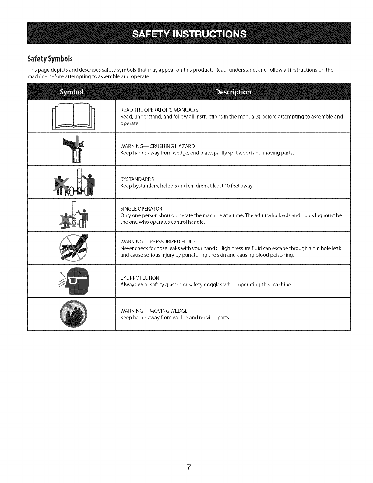
SafetySymbols
This page depicts and describes safety symbols that may appear on this product. Read, understand, and follow all instructions on the
machine before attempting to assemble and operate.
A
READ THE OPERATOR'S MANUAL(S)
Read, understand, and follow all instructions in the manual(s) before attempting to assemble and
operate
WARNING-- CRUSHING HAZARD
Keep hands away from wedge, end plate, partly split wood and moving parts.
BYSTANDARDS
Keep bystanders, helpers and children at least 10 feet away.
SINGLE OPERATOR
Only one person should operate the machine at a time. The adult who loads and holds log must be
the one who operates control handle.
WARNING-- PRESSURIZED FLUID
Never check for hose leaks with your hands. High pressure fluid can escape through a pin hole leak
and cause serious injury by puncturing the skin and causing blood poisoning.
EYE PROTECTION
Always wear safety glasses or safety goggles when operating this machine.
WARNING-- MOVING WEDGE
Keep hands away from wedge and moving parts.
7
_J
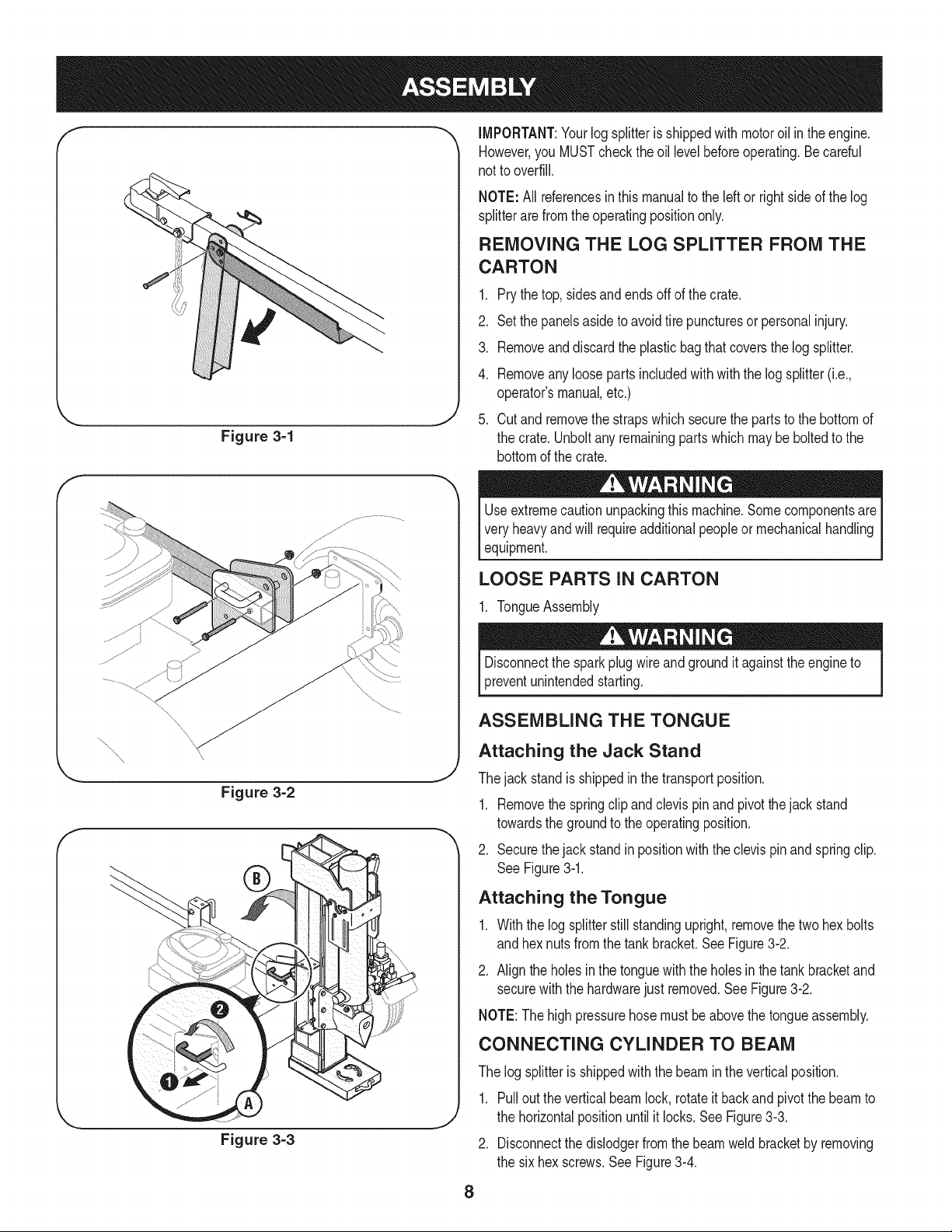
Figure 3=1
\
... j
Figure 3=2
Figure 3=3
IMPORTANT:Your log splitterisshippedwith motoroil in theengine.
However,you MUSTcheckthe oil levelbeforeoperating.Be careful
not to overfill.
NOTE: All referencesin this manualto the left or rightsideof thelog
splitterare from the operatingpositiononly.
REMOVING THE LOG SPLITTER FROM THE
CARTON
1. Prythe top,sidesandends off of the crate.
2. Set the panelsasideto avoidtire puncturesor personalinjury.
3. Removeand discardthe plasticbagthatcoversthe log splitter.
4. Removeany loosepartsincludedwithwiththe log splitter(i.e.,
operator'smanual,etc.)
5. Cut and removethe strapswhichsecurethe partsto the bottomof
the crate.Unboltany remainingparts which maybe boltedto the
bottomof the crate.
Useextremecautionunpackingthismachine.Somecomponentsare
veryheavyandwill requireadditionalpeopleor mechanicalhandling
equipment.
LOOSE PARTS IN CARTON
1. TongueAssembly
Disconnectthe sparkplug wireand groundit againstthe engineto
preventunintendedstarting.
ASSEMBLING THE TONGUE
Attaching the Jack Stand
Thejackstand isshippedin thetransportposition.
1. Removethe springclipand clevis pinandpivotthe jackstand
towardsthe groundto the operatingposition.
2. Securethejackstandin positionwiththeclevis pinandspringclip.
See Figure3-1.
Attaching the Tongue
1. Withthe logsplitterstill standingupright,removethe two hex bolts
and hexnutsfromthe tankbracket.SeeFigure3-2.
2. Align the holesinthe tonguewith the holesinthe tank bracketand
securewiththe hardwarejustremoved.See Figure3-2.
NOTE:The high pressurehosemustbe abovethe tongueassembly.
CONNECTING CYLINDER TO BEAM
The log splitteris shippedwiththe beamin the verticalposition.
1. Pullout the verticalbeamlock, rotateit backand pivot the beamto
the horizontalpositionuntil itlocks.See Figure3-3.
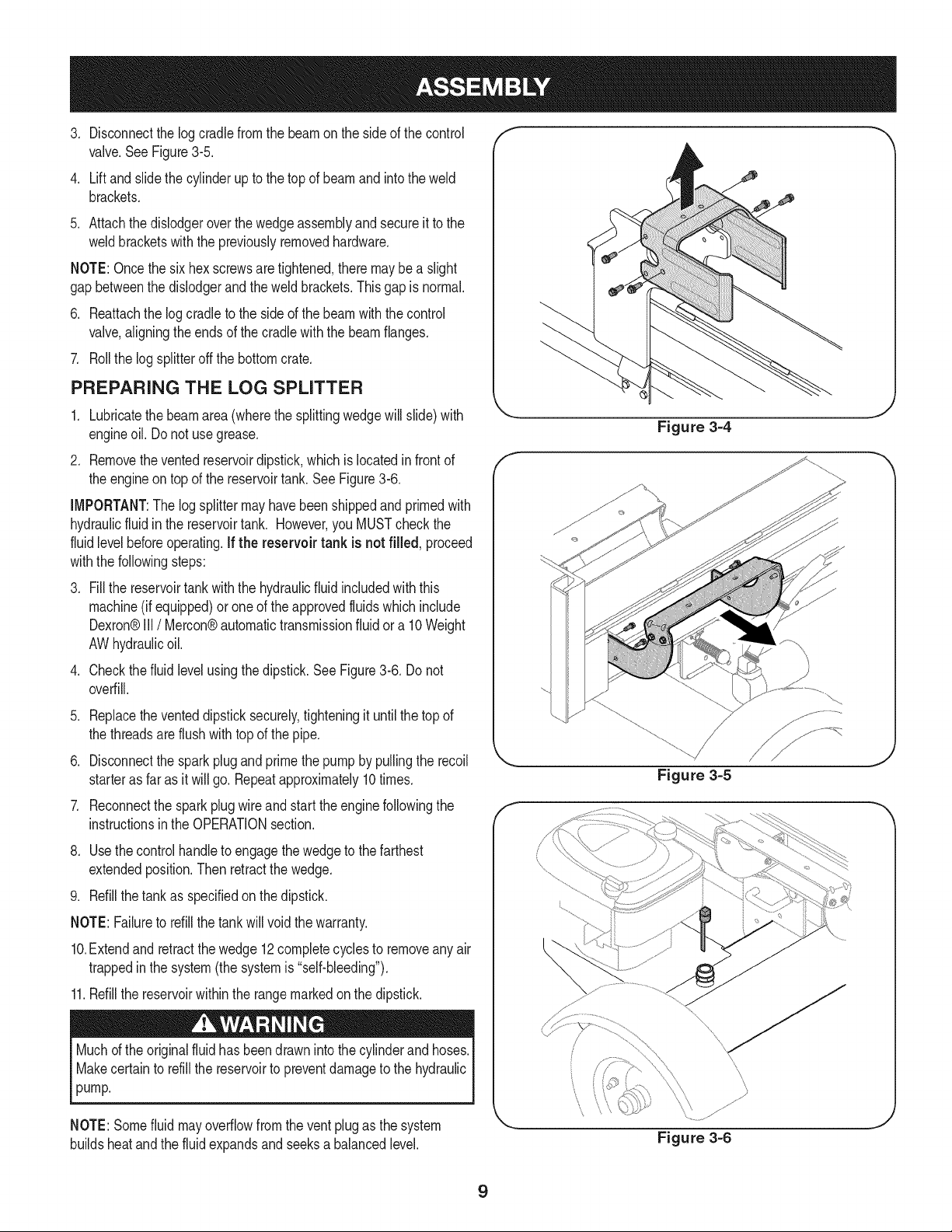
2. Disconnectthe dislodgerfromthe beamweldbracketby removing
the six hexscrews.SeeFigure3-4.
8
.
.
Disconnectthe logcradlefromthe beamon the sideof the control
valve.See Figure3-5.
Liftand slidethe cylinderup to the topof beamand intothe weld
brackets.
5. Attachthedislodgeroverthe wedgeassemblyand secureit to the
weldbracketswith the previouslyremovedhardware.
NOTE:Oncethe sixhex screwsaretightened,theremay be a slight
gapbetweenthe dislodgerand the weldbrackets.Thisgapis normal.
6. Reattachthe logcradleto the side of the beamwith the control
valve,aligningthe endsof the cradlewith the beamflanges.
7. Rollthe log splitteroff the bottomcrate.
PREPARING THE LOG SPLITTER
1. Lubricatethe beamarea (wherethe splittingwedgewill slide)with
engineoil. Do notuse grease.
2. Removethevented reservoirdipstick,which is locatedinfrontof
the engineon top of the reservoirtank. See Figure3-6.
IMPORTANT:The logsplittermayhavebeenshippedandprimedwith
hydraulicfluidin the reservoirtank. However,you MUSTcheckthe
fluidlevelbeforeoperating.If the reservoir tank is not filled, proceed
withthe followingsteps:
.
.
Fill the reservoirtankwiththe hydraulicfluidincludedwith this
machine(if equipped)or oneof theapprovedfluidswhichinclude
Dexron®III / Mercon®automatictransmissionfluid ora 10Weight
AWhydraulicoil.
Checkthefluid levelusingthedipstick.SeeFigure3-6. Do not
overfill.
.
Replacetheventeddipsticksecurely,tighteningit untilthe topof
the threadsare flush with top of the pipe.
6. Disconnectthe spark plugand primethe pumpby pullingthe recoil
starteras faras it will go. Repeatapproximately10times.
7. Reconnectthe sparkplugwireandstart the enginefollowingthe
instructionsin the OPERATIONsection.
8. Use thecontrol handleto engagethewedgeto the farthest
extendedposition.Then retractthe wedge.
9. Refillthe tankas specifiedon thedipstick.
NOTE:Failureto refillthe tankwill voidthe warranty.
10.Extendand retractthewedge 12completecyclesto removeanyair
trappedin the system(the systemis "self-bleeding").
11.Refillthe reservoirwithinthe rangemarkedon the dipstick.
Muchd the originalfluid hasbeendrawnintothe cylinderand hoses.
Makecertainto refillthe reservoirto preventdamageto the hydraulic
pump.
NOTE:Somefluid may overflowfromthe vent plug as the system
buildsheatand the fluidexpandsandseeksa balancedlevel.
Figure 3=4
Figure 3=5
\\\
"x
\
\
Figure 3=6
,J
9
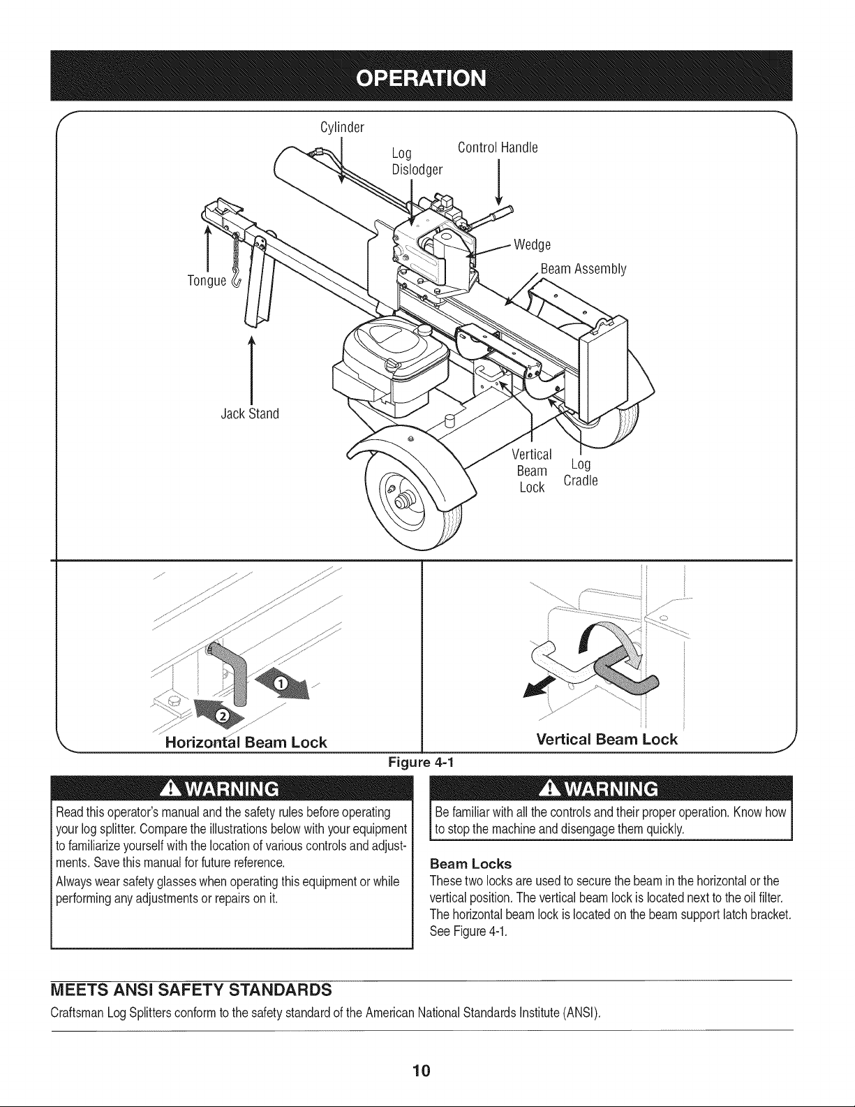
Cylinder
Log
Dislodger
Control Handle
Tongue
e
BeamAssembly
1
Jack Stand
Vertical
Beam Log
Lock Cradle
,_ Horizontai Beam Lock
Figure 4=1
Readthis operator'smanualand the safetyrulesbeforeoperating
yourlog splitter.Comparethe illustrationsbelowwith yourequipment
to familiarizeyourselfwiththe locationof variouscontrolsandadjust-
ments.Savethis manualfor futurereference.
Alwayswearsafetyglasseswhenoperatingthis equipmentor while
performinganyadjustmentsor repairson it.
Vertical Beam Lock
Befamiliarwithall the controlsandtheir properoperation.Knowhow
to stop the machineanddisengagethemquickly.
J
Beam Locks
Thesetwo locksareusedto securethe beamin the horizontalor the
verticalposition.The verticalbeam lockis locatednext to theoil filter.
The horizontalbeamlock is locatedonthe beamsupportlatch bracket.
See Figure4-1.
MEETS ANSI SAFETY STANDARDS
CraftsmanLogSplittersconformto the safetystandardof the AmericanNationalStandardsInstitute(ANSI).
10
ENGINE CONTROLS
Stop Switch
Pushthe switchto ON priorto chokingfor the enginestart;pushto
OFFto shutthe enginedown.
Choke Control
Thechokecontrol is usedto chokeoff the carburetorandassistin
startingthe engine.
Starter Handle
Thestarterhandleis locatedon the engine.Pull the starterhandleto
startengine.
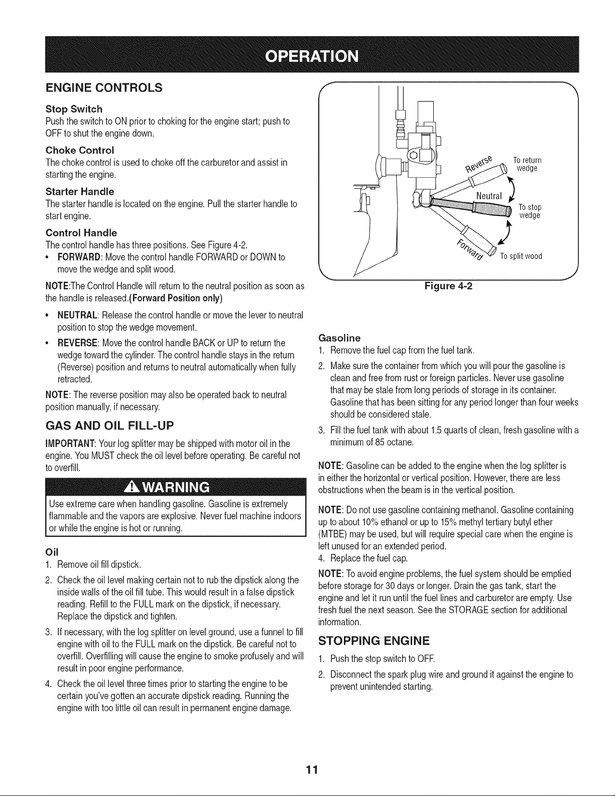
Control Handle
Thecontrol handlehasthreepositions.See Figure4-2.
• FORWARD:Movethe controlhandleFORWARDor DOWNto
movethe wedgeand splitwood.
NOTE:TheControlHandlewill returnto theneutralpositionas soonas
the handleisreleased.(ForwardPosition only)
NEUTRAL:Releasethecontrol handleor movetheleverto neutral
positionto stop thewedgemovement.
REVERSE:Movethecontrol handleBACKor UPto returnthe
wedgetowardthe cylinder.The controlhandle staysin the return
(Reverse)positionand returnsto neutralautomaticallywhenfully
retracted.
NOTE:The reversepositionmayalso beoperatedbackto neutral
positionmanually,if necessary.
GAS AND OiL FILL-UP
iMPORTANT:Yourlog splittermaybeshippedwith motoroil inthe
engine.YouMUSTcheckthe oil levelbeforeoperating.Be carefulnot
to overfill.
Useextremecarewhenhandlinggasoline.Gasolineisextremely
flammableandthe vaporsare explosive.Neverfuel machineindoors
or whilethe engineis hotor running.
Oil
1. Removeoil fill dipstick.
2. Checktheoil levelmakingcertainnot to rubthe dipstickalong the
insidewallsof the oil fill tube.Thiswould resultina falsedipstick
reading.Refillto the FULLmarkon thedipstick,if necessary.
Replacethedipstickand tighten.
3. If necessary,with the logsplitteronlevelground,usea funnelto fill
enginewithoilto the FULLmarkon the dipstick.Be careful notto
overfill.Overfillingwill causethe engineto smokeprofuselyandwill
resultinpoorengineperformance.
4. Checktheoil levelthreetimespriorto startingtheengineto be
certainyou'vegottenan accuratedipstickreading.Runningthe
enginewithtoo little oil can resultinpermanentenginedamage.
To return
wedge
Tostop
wedge
2
To split wood
Figure 4=2
Gasoline
1. Removethe fuelcap fromthefuel tank.
2. Makesurethe containerfromwhichyou will pourthe gasolineis
cleanand free fromrustorforeignparticles.Neverusegasoline
thatmaybe stalefromlongperiodsof storagein itscontainer.
Gasolinethat has beensittingfor any periodlongerthan fourweeks
shouldbeconsideredstale.
3. Fillthe fueltank with about 1.5quartsof clean,freshgasolinewitha
minimumof 85 octane.
NOTE:Gasolinecan be added to theenginewhen thelog splitteris
ineitherthe horizontalorverticalposition.However,thereare less
obstructionswhenthe beamis inthe verticalposition.
NOTE:Donot usegasolinecontainingmethanol.Gasolinecontaining
upto about10%ethanolor upto 15%methyltertiarybutyl ether
(MTBE)maybe used,but will requirespecialcare whenthe engineis
Idt unusedfor an extendedperiod.
4. Replacethe fuelcap.
NOTE:Toavoidengineproblems,thefuel systemshouldbe emptied
beforestoragefor30 daysor longer.Drainthe gas tank,startthe
engineand let it run untilthe fuel linesand carburetorare empty.Use
freshfuelthe nextseason.Seethe STORAGEsectionfor additional
information.
STOPPING ENGINE
1. Pushthe stopswitchto OFE
2. Disconnectthe sparkplugwireandgroundit againsttheengine to
preventunintendedstarting.
11
STARTING ENGINE
1. Attachthe sparkplugwireto the sparkplug.Makecertainthe metal
capon the endof the sparkplugis fastenedsecurelyoverthe metal
tip on the sparkplug.
2. Pushthe stopswitchto ON.
3. Movethe chokecontrolto the CHOKEposition.
4. Graspthe starterhandleand pullthe ropeout slowlyuntilthe
enginereachesitsstart of compressioncycle (ropewill pullslightly
harderat this point).
5. Pull the ropewitha rapid,continuous,full armstroke.Keepa firm
griponthe starterhandle.Letthe roperewindslowly.
6. Repeat,if necessary,untilthe enginestarts.Slowlyadjustthe
choketowardthe RUNposition.Wait untilthe enginerunssmoothly
beforeeachchoke adjustment.
7. If the enginefalters,movethecontrol leverto theCHOKEposition,
thenslowlyback to the RUNposition.
8. If weatheris cold, runthe wedgeupor downthe beam6 to 8 times
to circulatethe
Whenstartinga warmengine,the mufflerandsurroundingareasare
hotand can causea burn. Donot touchtheseareas.
USING THE LOG SPLITTER
.
2.
.
4.
Placethe logsplitterondry,levelground.
Placethe beamineitherthe horizontalor verticalpositionand lock
it in placewiththe appropriatelockingrod.
Blockthe front and back of bothwheels.
Placethe logagainsttheend plateandonly splitwoodin the
directionof the grain.
5. Tostabilizethe log,placeyour handonly onthe sides of the log.
Neverplace your handon the endbetweenthe log and the
splittingwedge.
6. Onlyone adultshouldstabilizethe logandoperatethe control
handle,so the operatorhasfull controloverthe logand thesplitting
wedge.
Control Handle
1. Movethe controlhandleFORWARDor DOWNto splitwood.
2. Releasethe controlhandleto stopthe wedgemovement.
3. Movethecontrol handleBACKor UPto returnthe wedge.
Log Dislodger
The log dislodgeris designedto removeany partiallysplitwoodfrom
the wedge.This mayoccur whilesplittinglargediameterwoodor
freshlycut wood.
Neverremovepartiallysplitwoodfromthe wedgewithyourhands.
Fingersmaybecometrappedbetweenthe splitwood.
1. To removepartiallysplit woodfrom thewedge, movethecontrol
handleto the REVERSEpositionuntilthe wedgeis fullyretractedto
allowthe splitwoodportionto contactthe logdislodger.
2. Once removedfromthe wedgewith the logdislodger,splitthe
woodfrom the oppositeendorin anotherlocation.
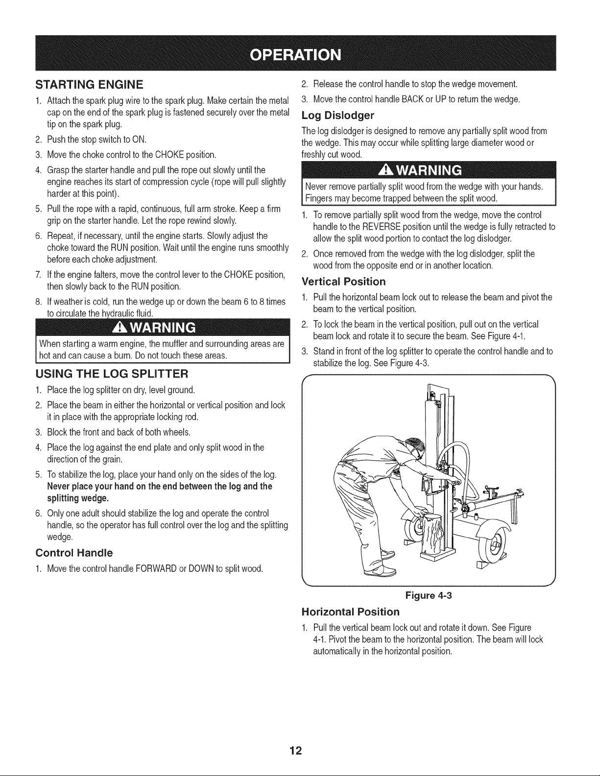
Vertical Position
1. Pullthe horizontalbeamlockout to releasethe beamand pivot the
beamto the verticalposition.
2. To lockthebeamin the verticalposition,pullout on the vertical
beamlock and rotateit to securethe beam.See Figure4-1.
3. Standin frontof the logsplitterto operatethe controlhandleandto
stabilizethe log. SeeFigure4-3.
Figure 4=3
Horizontal Position
1. Pullthe verticalbeamlockout and rotateit down.SeeFigure
4-1.Pivotthe beamto the horizontalposition.The beamwill lock
automaticallyin the horizontalposition.
12
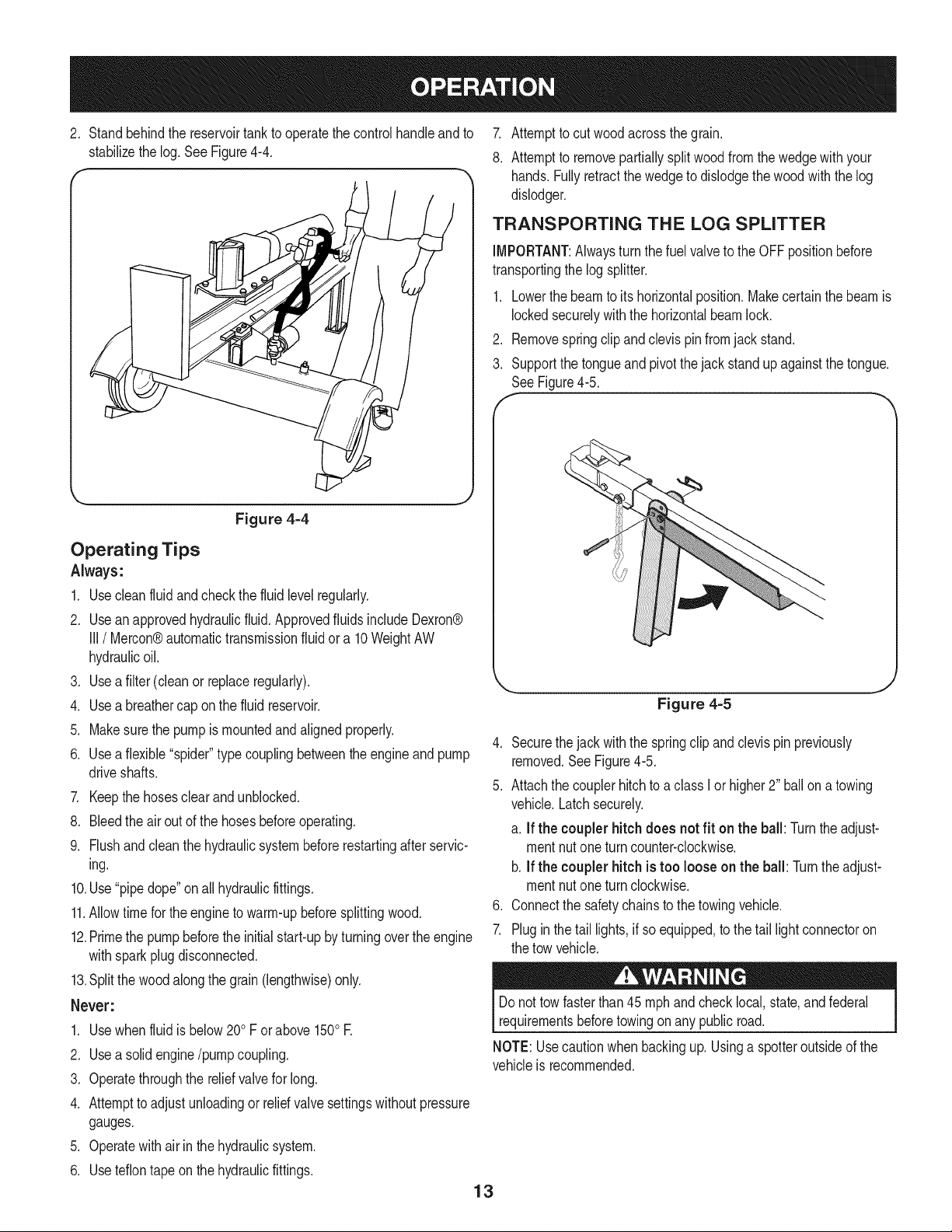
2, Standbehindthe reservoirtankto operatethe controlhandleandto 7.
stabilizethe log,See Figure4-4, 8,
Figure 4=4
Operating Tips
Always:
1. Usecleanfluidand checkthe fluid levelregularly.
2. Use an approvedhydraulicfluid.Approvedfluids includeDexron®
III / Mercon®automatictransmissionfluid ora 10WeightAW
hydraulicoil.
3. Use a filter (cleanor replaceregularly).
4. Use a breathercap onthe fluid reservoir.
5. Makesurethe pumpis mountedandalignedproperly.
6. Use a flexible"spider"typecouplingbetweenthe engineandpump
driveshafts.
7. Keepthe hosesclear and unblocked.
8. Bleedthe airout of the hoses beforeoperating.
9. Flushand cleanthe hydraulicsystembeforerestartingafterservic-
ing.
10.Use "pipedope"onall hydraulicfittings.
11.Allowtime forthe engineto warm-upbeforesplittingwood.
12.Primethe pumpbeforethe initialstart-upbyturningovertheengine
withsparkplugdisconnected.
13.Splitthe woodalongthe grain (lengthwise)only.
Never:
1. Usewhenfluidis below200F or above1500E
2. Use a solidengine/pumpcoupling.
3. Operatethroughthe reliefvalvefor long.
4. Attempttoadjust unloadingor relid valvesettingswithoutpressure
gauges.
5. Operatewith air in the hydraulicsystem.
6. Use teflontapeon the hydraulicfittings.
13
Attemptto cut woodacrossthe grain.
Attemptto removepartiallysplitwoodfromthe wedgewithyour
hands.Fullyretractthewedgeto dislodgethe woodwith the log
dislodger.
TRANSPORTING THE LOG SPLITTER
IMPORTANT:Alwaysturn the fuelvalve to the OFFpositionbefore
transportingthe log splitter.
1. Lowerthe beamto its horizontalposition.Makecertainthe beamis
lockedsecurelywiththe horizontalbeamlock.
2. Removespringclip andclevispinfromjack stand.
3. Supportthe tongueand pivot thejack standup againstthe tongue.
SeeFigure4-5.
Figure 4=5
4. Securethejack withthe springclip andclevispin previously
removed.See Figure4-5.
5. Attachthe couplerhitchto a class I or higher2" ballona towing
vehicle.Latchsecurely.
a. If the couplerhitchdoes notfit on the ball: Turntheadjust-
mentnutone turncounter-clockwise.
b. If the couplerhitch is too loose on the ball: Turntheadjust-
mentnutone turnclockwise.
6. Connectthe safetychainsto the towingvehicle.
7. Plugin thetail lights,if so equipped,to the tail light connectoron
the tow vehicle.
Donot towfasterthan 45mph and checklocal, state,and federal
requirementsbeforetowingon any public road.
NOTE:Usecautionwhenbackingup. Usinga spotteroutsideof the
vehicleis recommended.
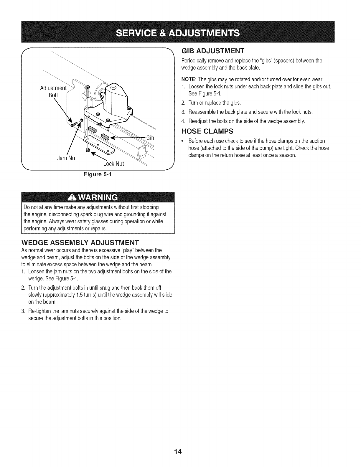
Adjustment
Bolt
Jam Nut
Lock Nut
.Gib
f
"_ GIB ADJUSTMENT
Periodicallyremoveand replacethe "gibs"(spacers)betweenthe
wedgeassemblyand the backplate,
NOTE:The gibsmaybe rotatedand/or turnedoverfor evenwear.
1. Loosenthe locknutsundereachback plateand slidethe gibsout.
See Figure5-1.
2. Turnor replacethe gibs.
3. Reassemblethe backplateand securewith the locknuts.
4. Readjustthe boltsonthe side of thewedgeassembly.
HOSE CLAMPS
• Beforeeachusecheck to seeif thehoseclampson the suction
hose (attachedto the sideof the pump)are tight.Checkthe hose
clampson the returnhoseat least oncea season.
Figure 5=1
Do notat any time makeanyadjustmentswithoutfirststopping
theengine,disconnectingspark plugwire andgroundingit against
theengine.Alwayswearsafetyglassesduringoperationor while
[performng anyadjustmentsor repars.
WEDGE ASSEMBLY ADJUSTMENT
As normalwearoccursand thereis excessive"play"betweenthe
wedgeand beam,adjustthe boltsonthe sideof the wedgeassembly
to eliminateexcessspacebetweenthe wedgeandthe beam.
1. Loosenthejam nutson the two adjustmentboltson the sideof the
wedge.SeeFigure5-1.
2. Turnthe adjustmentboltsinuntil snugand thenback them off
slowly(approximately1.5turns)untilthe wedgeassemblywill slide
onthe beam.
.
Re-tightenthe jam nuts securelyagainsttheside of the wedgeto
securethe adjustmentboltsin thisposition.
14
]i!ill
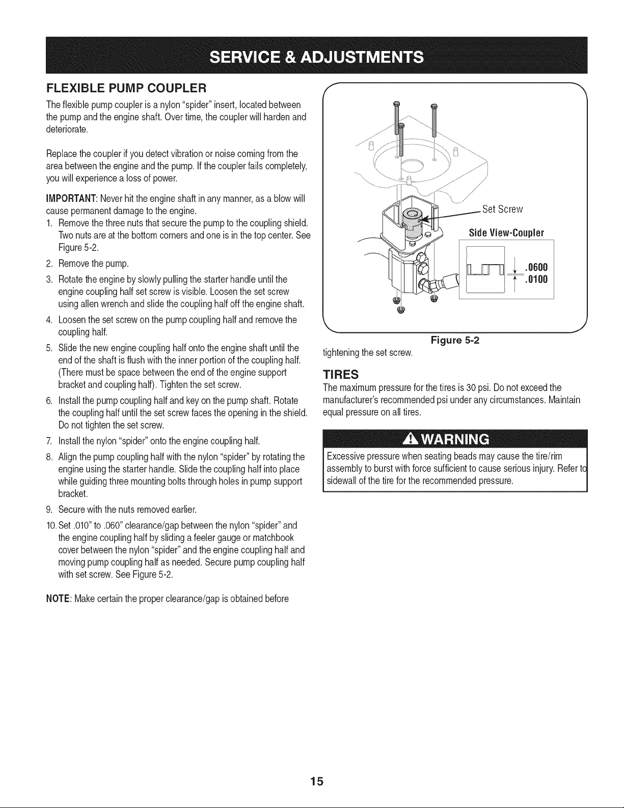
FLEXIBLE PUMP COUPLER
Theflexible pumpcoupleris a nylon"spider"insert,locatedbetween
the pumpandthe engineshaft.Overtime,the couplerwillhardenand
deteriorate.
Replacethecouplerif you detectvibrationor noisecomingfromthe
areabetweenthe engineand the pump.If thecouplerfailscompletely,
youwill experiencea lossof power.
iMPORTANT:Neverhit the engineshaftin any manner,as a blowwill
causepermanentdamageto the engine.
1. Removethethree nutsthat securethe pumpto the couplingshield.
Twonutsareat the bottomcornersandoneis inthe top center.See
Figure5-2.
2. Removethepump.
3. Rotatethe engineby slowlypullingthe starterhandleuntilthe
enginecouplinghalf set screwis visible.Loosenthe set screw
usingallen wrenchand slidethe couplinghalfoff the engineshaft.
4. Loosenthe setscrewonthe pumpcouplinghalf andremovethe
couplinghalf.
5. Slide thenewengine couplinghalf ontotheengine shaftuntil the
endof the shaftis flush with the innerportionof the couplinghalf.
(Theremustbe space betweenthe endof the enginesupport
bracketandcouplinghalf).Tightenthe set screw.
6. Installthe pumpcouplinghalfand key on thepump shaft.Rotate
the couplinghalf untilthe set screwfaces theopeningin the shield.
Do nottightenthe set screw.
7. Installthe nylon"spider"ontothe enginecouplinghalf.
8. Align thepumpcouplinghalfwiththe nylon"spider"by rotatingthe
engineusingthe starterhandle.Slidethecouplinghalfinto place
whileguidingthreemountingbolts throughholesin pumpsupport
bracket.
9. Securewith the nutsremovedearlier.
10.Set .010"to .060"clearance/gapbetweenthe nylon"spider"and
the enginecouplinghalf byslidinga feelergaugeor matchbook
coverbetweenthenylon"spider"andthe enginecouplinghalf and
movingpumpcouplinghalfas needed.Securepumpcouplinghalf
withsetscrew.SeeFigure5-2.
/
Screw
Side View-Coupler
; .oooo
.0100
Figure 5=2
tighteningthe set screw.
J
TIRES
The maximumpressurefor the tires is 30 psi.Do notexceedthe
manufacturer'srecommendedpsi underany circumstances.Maintain
equalpressureonall tires.
Excessivepressurewhenseatingbeadsmaycausethe tire/rim
assemblyto burstwithforcesufficientto cause seriousinjury. Refertc
sidewallof the tirefor the recommendedpressure.
NOTE:Makecertainthe properclearance/gapis obtainedbefore
15
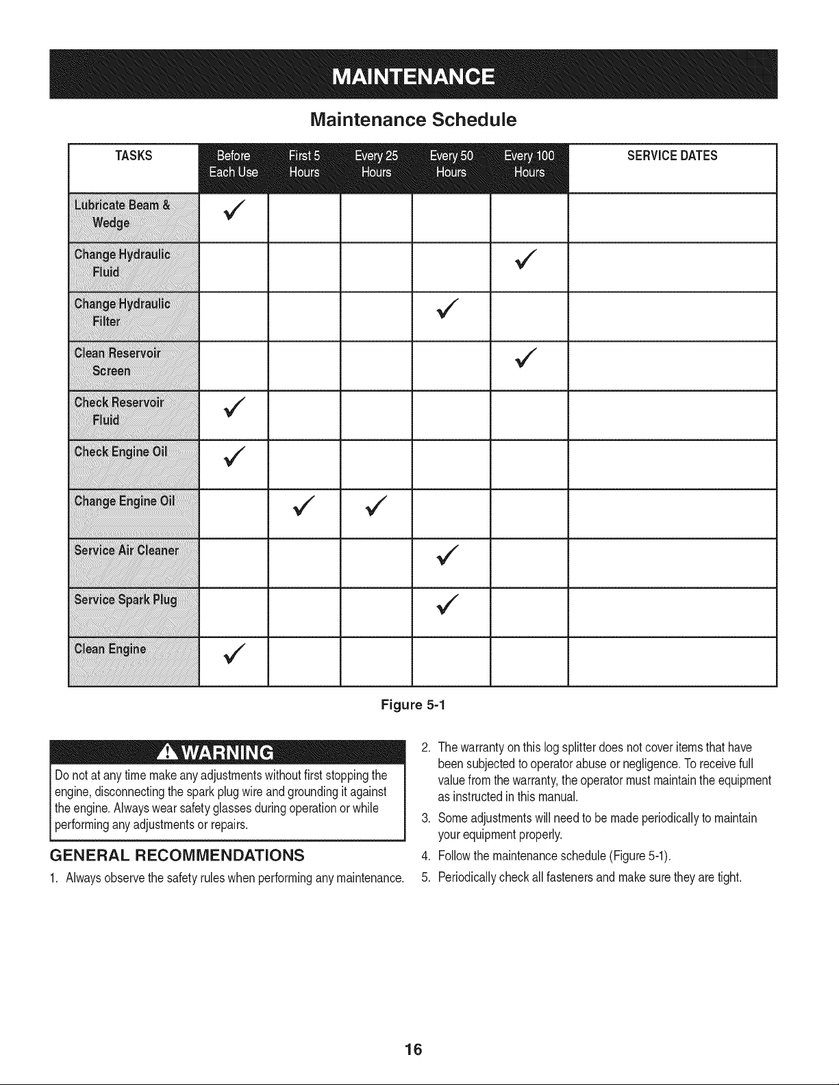
TASKS
Maintenance Schedule
v
Figure 5=1
Do notat any time makeanyadjustmentswithoutfirststoppingthe
engine,disconnectingthe spark plugwire andgroundingit against
theengine.Alwayswearsafetyglassesduringoperationor while
performinganyadjustmentsor repairs.
SERVICEDATES
GENERAL RECOMMENDATIONS
1. Alwaysobservethe safetyruleswhenperformingany maintenance.
.
The warrantyon this logsplitterdoesnotcoveritemsthathave
beensubjectedto operatorabuseor negligence.Toreceivefull
valuefrom the warranty,the operatormust maintainthe equipment
as instructedin this manual.
3. Someadjustmentswill needto be madeperiodicallyto maintain
yourequipmentproperly.
4. Followthe maintenanceschedule(Figure5-1).
5. Periodicallycheckallfastenersandmakesurethey are tight.
16
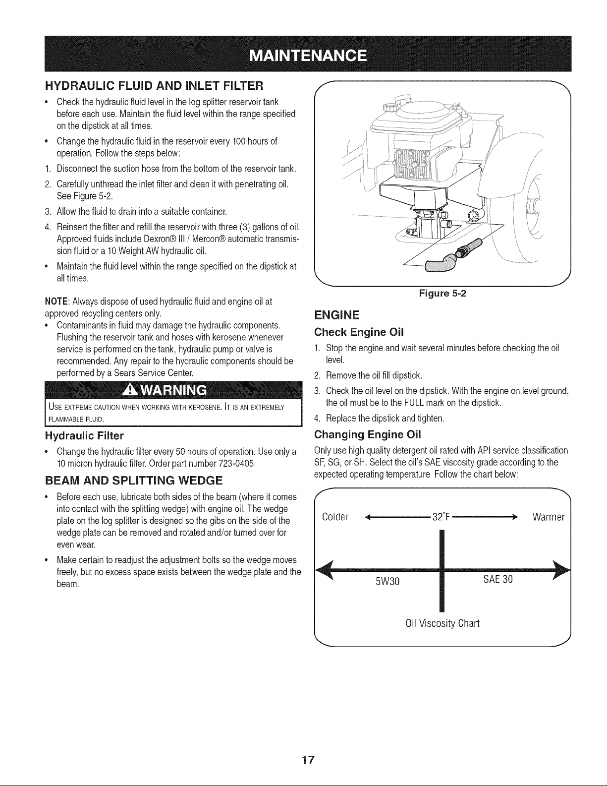
HYDRAULIC FLUID AND iNLET FILTER
Checkthehydraulicfluid levelin the logsplitterreservoirtank
beforeeach use. Maintainthe fluidlevelwithinthe rangespecified
onthe dipstickat all times.
Changethe hydraulicfluid inthe reservoirevery 100 hoursof
operation.Followthe stepsbelow:
Disconnectthe suctionhosefromthe bottomof the reservoirtank.
2. Carefullyunthreadthe inletfilter and clean it with penetratingoil.
SeeFigure5-2.
3. Allowthefluid to drain intoa suitablecontainer.
4. Reinsertthe filterandrefillthe reservoirwith three(3) gallonsof oil.
Approvedfluids includeDexron®III/Mercon® automatictransmis-
sionfluid ora 10WeightAWhydraulicoil.
• Maintainthe fluid levelwithinthe rangespecifiedon the dipstickat
alltimes.
NOTE:Alwaysdisposeof usedhydraulicfluidand engineoilat
approvedrecyclingcentersonly.
• Contaminantsin fluidmaydamagethe hydrauliccomponents.
Flushingthe reservoirtank and hoseswithkerosenewhenever
serviceisperformedon the tank, hydraulicpumpor valve is
recommended.Any repairto the hydrauliccomponentsshouldbe
performedby a SearsServiceCenter.
USE EXTREME CAUTIONWHEN WORKING WITH KEROSENE. IT IS AN EXTREMELY
FLAMMABLEFLUID.
Hydraulic Filter
• Changethe hydraulicfilterevery50 hoursof operation.Useonly a
10micronhydraulicfilter.Orderpart number723-0405.
BEAM AND SPLITTING WEDGE
Beforeeach use,lubricatebothsides of the beam(whereit comes
intocontactwith the splittingwedge)withengineoil. The wedge
plateon the log splitterisdesignedsothe gibs on the sideof the
wedgeplatecan be removedandrotatedand/orturnedoverfor
evenwear.
• Makecertain to readjustthe adjustmentbolts sothe wedgemoves
freely,but no excessspaceexists betweenthe wedgeplateand the
beam.
/
Figure 5=2
ENGINE
Check Engine Oil
1. Stoptheengineandwait severalminutesbeforecheckingtheoil
level.
2. Removethe oilfill dipstick.
3. Checkthe oil levelon the dipstick.With the engineon levelground,
the oil mustbeto the FULLmarkon thedipstick.
4. Replacethe dipstickand tighten.
Changing Engine Oil
Onlyusehigh quality detergentoil ratedwith API serviceclassification
SF,SG, or SH.Selecttheoil's SAEviscositygrade accordingto the
expectedoperatingtemperature.Followthechart below:
Warmer
5W30
SAE 30
0il Viscosity Chart
17
NOTE:Althoughmulti-viscosityoils (5W30,10W30,etc.)improve
startingin cold weather,theywill resultin increasedoilconsumption
whenusedabove32°R Checkyour engineoil levelmorefrequentlyto
avoidpossibleenginedamagefrom runninglow onoil.
Changethe engineoil after the first five hoursof operation,andevery
50 hoursthereafter.Changethe oilevery25hoursof operationif the
engineis operatedunder heavyload or in highambienttemperatures.
To Drain Oil
Drainthe oilwhilethe engineis warm.Followthe instructionsgiven
below.
.
2.
Removethe drainplugonthe engineand drain the oilinto a
suitablecontainer.
Whentheengine is drainedof all oil, replacethedrain plug and
refillwithapproximately20oz.of fresh oil. Referto GasAnd Oil
Fill-upinthe OPERATIONsection.
Service Air Cleaner
Theair cleanerpreventsdamagingdirt, dust,etc.,fromenteringthe
carburetorandbeingforcedintothe engineandis importantto engine
lifeand performance.
Neverrunthe enginewithoutan aircleanercompletelyassembled.
Servicethe cartridgeevery25 operatinghoursor everyseason.
Servicethe cartridgemoreoften underdustyconditions.
To Service Air Filter
.
2.
Loosenthe air cleanercoverscrew,butdo not removethe screw
fromthe cover.Swingthe coverdownto removefromthehinge.
Inspectthe filterfor discolorationor dirt accumulation.If eitheris
present,proceedas follows:
a. Cleanthe insideof bodyandcoverthoroughlyand removethe
cartridge.
b. Reassemblethe newcartridgein the body.Swingthe cover
downand tightenthe screwloosenedearlier.
Temperatureof mufflerand nearbyareasmayexceed 150° F(65°C).
Avoidtheseareas.
seasonor every50 hoursof operation.
• Cleanthe areaaroundthe sparkplug.Removeand inspectthe
sparkplug.
• Replacethe sparkplugif theelectrodesarepitted,burnedor the
porcelainis cracked.
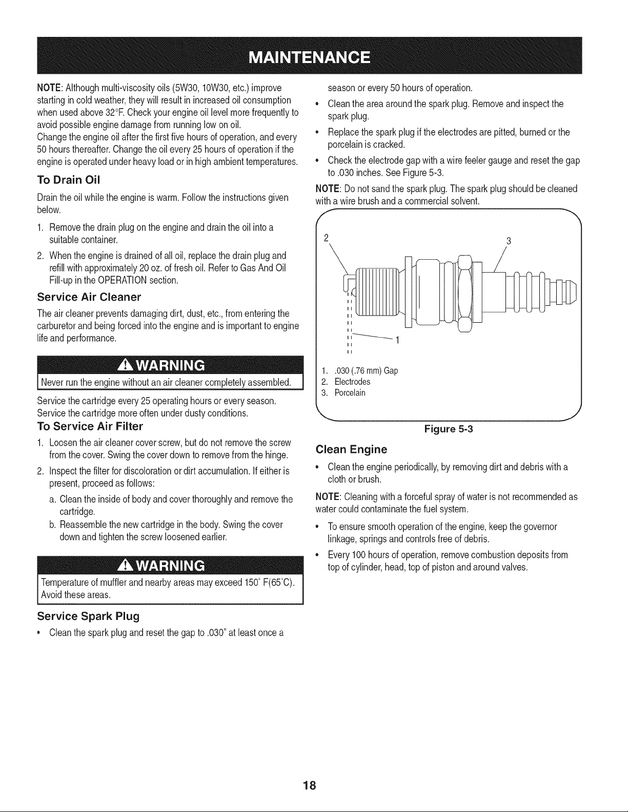
• Checkthe electrodegapwitha wire feelergaugeandresetthe gap
to .030inches.See Figure5-3.
NOTE: Donot sandthe sparkplug.The sparkplugshouldbe cleaned
witha wire brushanda commercialsolvent.
f
1..030 (.76 mm) Gap
2. Electrodes
3. Porcelain
J
Figure 5=3
Clean Engine
• Cleanthe engineperiodically,by removingdirt and debriswith a
clothor brush.
NOTE:Cleaningwitha forcefulsprayof wateris not recommendedas
watercouldcontaminatethe fuelsystem.
• Toensuresmoothoperationof the engine,keepthe governor
linkage,springsandcontrolsfree of debris.
• Every100 hoursof operation,removecombustiondepositsfrom
top of cylinder,head,topof pistonandaroundvalves.
Service Spark Plug
* Cleanthe sparkplugandresetthe gap to .030"at leastonce a
18
Prepareyour log splitterfor storageat the endof the seasonor if the
logsplitterwill not beusedfor 30daysor more.
WARNING:Neverstorethe machinewith fuel inthe fueltank inside
of buildingwherefumesmay reachan open flameor sparkor where
ignitionsourcesare presentsuchas hot waterandspaceheaters,
furnaces,clothesdyers,stoves,electricmotors,etc.
NOTE:A yearly check-upbyyour localSearsservicecenteris a good
wayto ensureyourlog splitterwill providethe maximumperformance
nextseason.
LOG SPLITTER
1. Cleanthe logsplitterthoroughly.
2. Wipethe logsplitterwithanoiledragto preventrust,especiallyon
thewedgeand the beam.
ENGINE
IMPORTANT:Itis importantto preventgumdepositsfrom forming
inthe essentialfuel systempartssuchas thecarburetor,fuel filter,
fuel hoseor tank during storage.Also,alcoholblendedfuels (called
gasoholor usingethanolor methanol)canattract moisturewhichleads
to separationand formationof acidsduringstorage.Acidic gascan
damagethe fuelsystemof anenginewhilein storage.
1. Drainthe fueltank. Alwaysdrainthe fuel intoan approvedcontainer
outdoorsawayfromopenflame.Be surethe engineis cool. Donot
smokewhile handlingthe fuel.
2. Start the engineandlet it rununtil thefuel linesand carburetorare
empty.
IMPORTANT:Neveruseengineor carburetorcleanerproductsin the
fuel tank or permanentdamagemayoccur.Usefreshfuel next season.
3. Removethe sparkplug,pourapproximately1/2oz. of engineoilinto
cylinderandcrankit slowlyto distributethe oil.
4. Replacethe sparkplug.
NOTE: Fuelstabilizeris an acceptablealternativein minimizingthe
formationof fuel gumdepositsduringstorage.
Pleasefollowthe instructionsbelowfor storingyourlog splitterwith
fuel and stabilizerin the engine:
1. Add stabilizerto the gasolinein the fueltank or storagecontainer.
Alwaysfollowthe mix ratiofoundon the stabilizercontainer.
2. Runtheengine at least10minutesafteraddingstabilizerto allow
the stabilizerto reachthe carburetor.
IMPORTANT:Donot drainthegas tank and carburetorif usingfuel
stabilizer.Drainallthe oil fromthecrankcase(thisshouldbedone
afterthe enginehas beenoperatedandis still warm)andrefillthe
crankcasewithfreshoil.
OTHER
• Donot storethe gasolinefrom one seasonto another.
• Replaceyourgasolinecan if it starts to rust.
Storethe logsplitterin a clean,dry area.Do not storeit nextto
any corrosivematerials,suchas fertilizer.
• Wipethe equipmentwithan oiledragto preventrust.
19
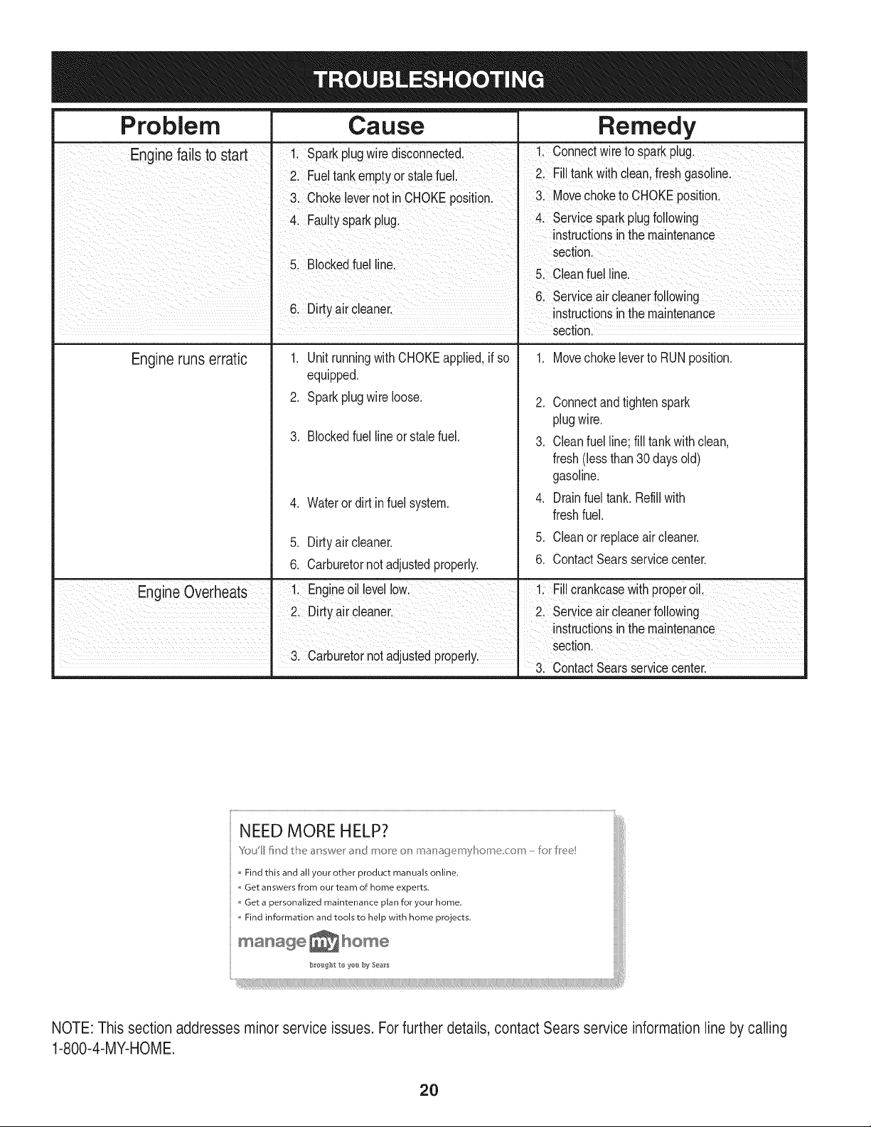
Problem Cause
Remedy
I I section.
Engine runs erratic
1. Unitrunningwith CHOKEapplied,if so
equipped.
2. Sparkplugwire loose.
3. Blockedfuel lineor stalefuel.
4. Wateror dirt in fuel system.
5. Dirtyair cleaner.
6. Carburetornot adjustedproperly.
1. Movechoke leverto RUNposition.
.
3.
.
5.
6.
Connectandtightenspark
plugwire.
Cleanfuel line;fill tankwithclean,
fresh(lessthan30 days old)
gasoline.
Drainfuel tank.Refill with
freshfuel.
Cleanor replaceair cleaner.
ContactSearsservicecenter.
3. Carburetornotadjustedproperly.
3. ContactSearsserv ce center.
NEED MORE HELP?
Youll find d_e answer and moe or_ mar_agemyl_ome corn -k'_r Iree!
Find this and all your other product manuals online.
,, Get answers from our team of home experts.
Get a personalized maintenance plan for your home.
,, Find information and tools to help with home projects.
manage _ home
bro'_gl_t to yes by Sea_
NOTE: This section addresses minorservice issues. Forfurther details, contact Sears serwce information line by calling
1-800-4-MY-HOME
2O
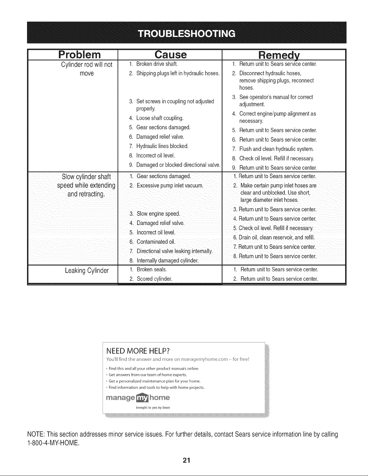
Problem
Cylinder rod will not
move
Cause
1. Brokendriveshaft.
2. Shippingplugsleft in hydraulichoses.
,
4.
Remedy
1. Returnunitto Searsservicecenter.
2. Disconnecthydraulichoses,
removeshippingplugs,reconnect
hoses.
,
Setscrewsin couplingnot adjusted
properly.
4.
Looseshaftcoupling.
Seeoperator'smanualfor correct
adjustment.
Correctengine/pumpalignmentas
necessary.
5. Gearsectionsdamaged.
6. Damagedreliefvalve.
7. Hydrauliclinesblocked.
8. Incorrectoil level.
5. Returnunitto Searsservicecenter.
6. Returnunitto Searsservicecenter.
7. Flushand clean hydraulicsystem.
8. Checkoil level. Refillif necessary.
9. Damagedor blockeddirectionalvalve. 9. Returnunitto Searsservicecenter.
Slow cylinder shaft I 1. Gearsectionsdamaged. 1. Returnunitto Searsservicecenter.
speed while extendng 2 Excessivepumpinletvacuum. 2. Makecertain pumpinlethosesare
and retractng c ear and unblocked.Useshort
" largediameter nlethoses.
3 Returnunt to Searsserv ce center
3. Slowenginespeed.
4 Returnunt to Searsservce center
4. Damagedreliefvalve
5. ncorrecto' eve. 5. Checkoil level. Ref l if necessary.
6 Dran o c eanreservor andref
6. Contaminatedoil.
I 7 Returnunt to Searsserv ce center
7, Directionalvalveleaking nternally.
8 Returnunitto Searsservicecenter.
8. nterna y damagedcy nder.
Leaking Cylinder 1. Brokenseals. 1. Returnunitto Searsservicecenter.
2. Scoredcylinder. 2. Returnunitto Searsservicecenter.
NEED MORE HELP?
You'll lind the _n wel ahd more or_ m4_r_4_()emyhome corn - Io[ IFee
o Find this and all your other product manuals online.
o Get answers from our team of home experts.
Get a personalized maintenance plan for your home.
o Find information and tools to help with home projects.
brought to yo-g_ 'by Se_rs .....
_HHH_
_i!!!:!i!i!!!!i!i!!i!i!!i!i!!i!i!!i!i!!i!i!!i!i!!i!i!!i!i!!i!i!!i!i!!i!i!!i!i!!i!i!!i!i!!i!i!!i!i!!i!i!!i!i!!i!i!!i!i!!i!i!!i!i!!i!i!!i!i!!i!i!!i!i!!i!i!!i!i!!i!i!!i!i!!i!i!!i!i!!i!i!!i!i!!i!i!!i!i!!i!i!!i!i!!i!i!!i!i!!i!i!!i!i!!i!i!!i!i!!i!i!!i!i!!i!i!!i!i!!i!i!!i!i!!i!i!!i!i!!i!i!!i!i!!i!i!!i!i!!i!i!!i!i!!i!i!!i!i!!i!i!!i!i!!i!i!!i!i!!i!i!_i!iiii!;¸
NOTE: This section addresses minor service issues. For further details,contact Sears service information line by calling
1-800-4-MY-HOME.
21
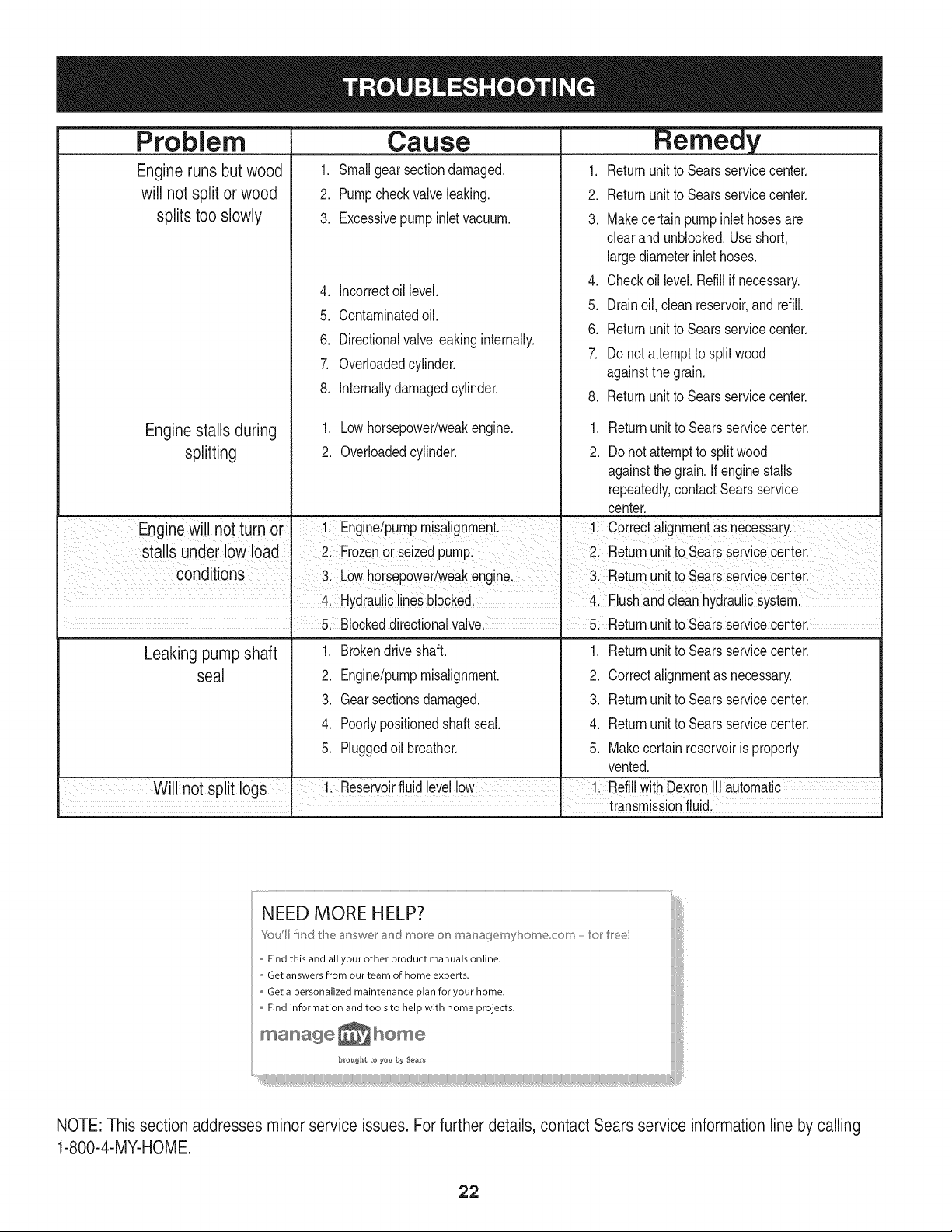
Problem
Engineruns but wood
will not split or wood
splits too slowly
Engine stalls during
splitting
Csuse
1. Smallgear sectiondamaged.
2. Pumpcheckvalveleaking.
3. Excessivepumpinletvacuum.
4. Incorrectoil level.
5. Contaminatedoil.
6. Directionalvalve leakinginternally.
7. Overloadedcylinder.
8. Internallydamagedcylinder.
1. Lowhorsepower/weakengine.
2. Overloadedcylinder.
Remedy
1. Returnunitto Searsservicecenter.
2. Returnunitto Searsservicecenter.
3. Makecertain pumpinlethosesare
clearand unblocked.Use short,
largediameterinlethoses.
4. Checkoil level. Refillif necessary.
5. Drainoil, cleanreservoir,and refill.
6. Returnunitto Searsservicecenter.
7. Do notattemptto splitwood
againstthegrain.
8. Returnunitto Searsservicecenter.
.
2.
Returnunitto Searsservicecenter.
Do notattemptto splitwood
againstthegrain. Ifenginestalls
repeatedly,contact Searsservice
center.
Engine Willnotturn or Engine/pumPmisalignment. I 1: Coirect alignmentas necessaryl
stalls under lowload Frozenorseizedpump Returnunitto Seaisservicecenter.
condtons LowhorSepOwer/weakeng ne J 3 Returnunt t0 searsservCecenter
' i 1
Hydrauliclinesb!ocked, 4, Flushand cleanhydraulicsysteml
. 5: Blockeddirectionalvalvel. 5: Returnunitto Searsservicecenter.
Leaking pumpshaft
seal
1. Brokendrive shaft.
2. Engine/pumpmisalignment.
3. Gearsectionsdamaged.
4. Poorlypositionedshaft seal.
5. Pluggedoil breather.
1. Returnunitto Searsservicecenter.
2. Correctalignmentas necessary.
3. Returnunitto Searsservicecenter.
4. Returnunitto Searsservicecenter.
5. Makecertain reservoiris properly
vented.
.... Will not split logs ' 1. Reservorfud eve ow. 1. Ref Wth Dexron automatc
, . transmissionfluid.
NEED MORE HELP?
Yo_/II fired tt_e answe,_" a_d more o__ mar_afjemyl_ome corn -Io_ Iree!
,, Find this and all your other product manuals online.
" Get answers from our team of home experts.
,, Get a personalized maintenance plan for your home.
Find information and tools to help with home projects.
maHage _ home
b_e_t to ye_._by Sea_s
NOTE: This section addresses minorservice issues. Forfurther details, contact Sears service information line by calling
1-800-4-MY-HOME.
22

23
A
24
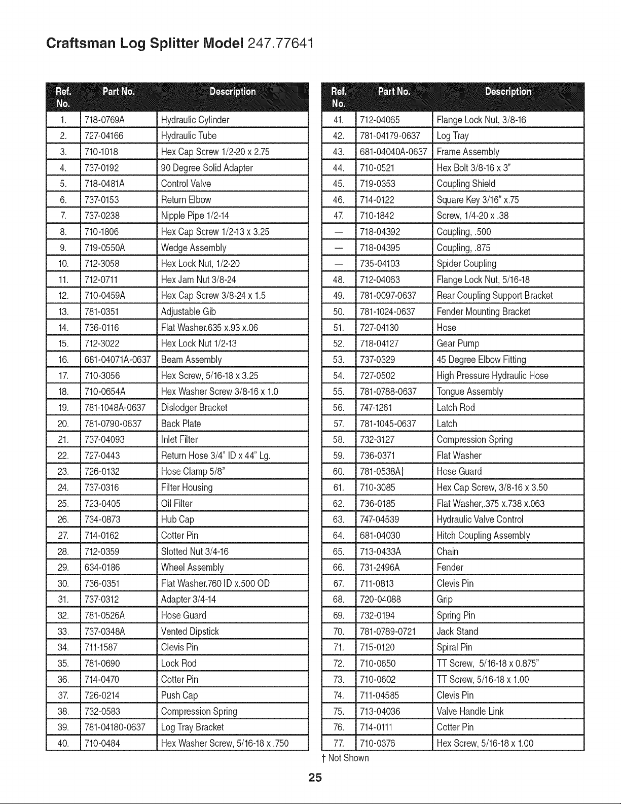
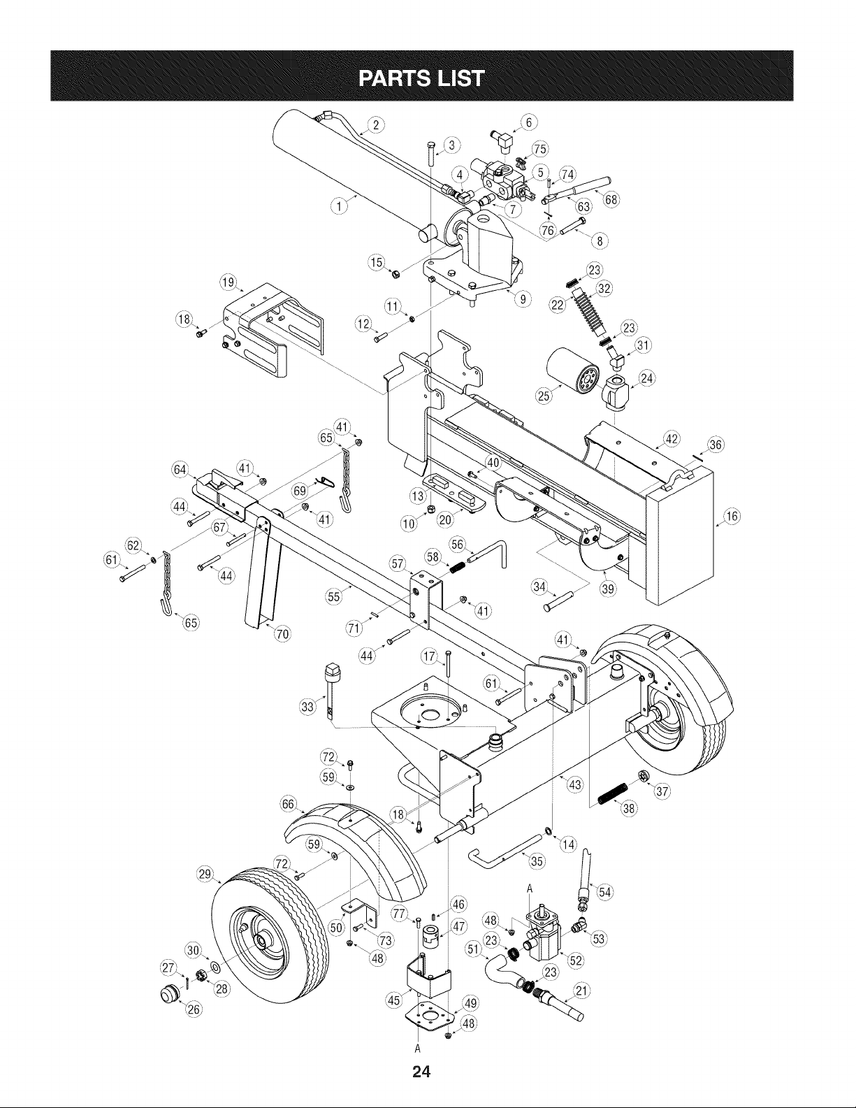
Craftsman Log Splitter Model 247.77641
718-0769A HydraulicCylinder
2. 727-04166 HydraulicTube
3. 710-1018 HexCap Screw 1/2-20x 2.75
4. 737-0192 90 DegreeSolidAdapter
5. 718-0481A ControlValve
6. 737-0153 ReturnElbow
7. 737-0238 NipplePipe1/2-14
8. 710-1806 HexCap Screw 1/2-13x 3.25
9. 719-0550A WedgeAssembly
10. 712-3058 HexLockNut,1/2-20
11. 712-0711 HexJam Nut3/8-24
12. 710-0459A Hex CapScrew3/8-24x 1.5
13. 781-0351 AdjustableGib
14. 736-0116 FiatWasher.635x.93x.06
15. 712-3022 HexLockNut1/2-13
16. 681-04071A-0637 BeamAssembly
17. 710-3056 HexScrew,5/16-18x 3.25
18. 710-0654A HexWasherScrew3/8-16x 1.0
19. 781-1048A-0637 DislodgerBracket
20. 781-0790-0637 BackPlate
21. 737-04093 inlet Filter
22. 727-0443 ReturnHose3/4" IDx 44" Lg.
23. 726-0132 HoseClamp5/8"
24. 737-0316 FilterHousing
25. 723-0405 OilFilter
26. 734-0873 HubCap
27. 714-0162 CotterPin
28. 712-0359 SlottedNut3/4-16
29. 634-0186 WheelAssembly
30. 736-0351 FiatWasher.760ID x.500OD
31. 737-0312 Adapter3/4-14
32. 781-0526A HoseGuard
33. 737-0348A VentedDipstick
34. 711-1587 ClevisPin
35. 781-0690 LockRod
36. 714-0470 CotterPin
37. 726-0214 PushCap
38. 732-0583 CompressionSpring
39. 781-04180-0637 LogTrayBracket
40. 710-0484 HexWasherScrew,5/16-18x .750
712-04065 FlangeLock Nut,3/8-16
42. 781-04179-0637 LogTray
43. 681-04040A-0637 FrameAssembly
44. 710-0521 HexBolt3/8-16x 3"
45. 719-0353 CouplingShield
46. 714-0122 SquareKey3/16"x.75
47. 710-1842 Screw,1/4-20x .38
-- 718-04392 Coupling,.500
-- 718-04395 Coupling,.875
-- 735-04103 SpiderCoupling
48. 712-04063 FlangeLockNut,5/16-18
49. 781-0097-0637 RearCouplingSupportBracket
50. 781-1024-0637 FenderMountingBracket
51. 727-04130 Hose
52. 718-04127 Gear Pump
53. 737-0329 45 DegreeElbowFitting
54. 727-0502 HighPressureHydraulicHose
55. 781-0788-0637 TongueAssembly
56. 747-1261 LatchRod
57. 781-1045-0637 Latch
58. 732-3127 CompressionSpring
59. 736-0371 FiatWasher
60. 781-0538At HoseGuard
61. 710-3085 HexCapScrew,3/8-16x 3.50
62. 736-0185 FiatWasher,.375x.738x.063
63. 747-04539 HydraulicValveControl
64. 681-04030 HitchCouplingAssembly
65. 713-0433A Chain
66. 731-2496A Fender
67. 711-0813 ClevisPin
68. 720-04088 Grip
69. 732-0194 SpringPin
70. 781-0789-0721 Jack Stand
71. 715-0120 SpiralPin
72. 710-0650 TT Screw, 5/16-18x 0.875"
73. 710-0602 TT Screw,5/16-18x 1.00
74. 711-04585 ClevisPin
75. 713-04036 ValveHandleLink
76. 714-0111 CotterPin
77. 710-0376 HexScrew,5/16-18x 1.00
t NotShown
25
5O
51
383_
718_
741
306
m
525 i
524 _
11
1330 REPAIR MANUAL I
26
Craftsman Engine Model No. 126L02
For Log Splitter Model 247.77641
968
445
81
613
977 CARBURETOR
GASKET SET
365
633A ®
633 G
276
121 CARBURETOR OVERHAUL KIT
633G
633A @
836
m
29_ 97o%
692 I
633A®
104
137_
276 Q
276 O
@
163_
108
127 _
(5
°33
130 _ O
95
617
m
276
@
]
27
627
347
497 4
78
304
363
930
23
332
455
i
601
1036 EMiSSiONS LABEL i
J
55
i
1 OO5
6s_'
58
592
"° S 9
ssg O
456 _
597 _
6O
28
Craftsman Engine Model No. 126L02
For Log Splitter Model 247.77641
i1329 REPLACEMENT ENGINEJ
i
615
404
616
505 _
m
29

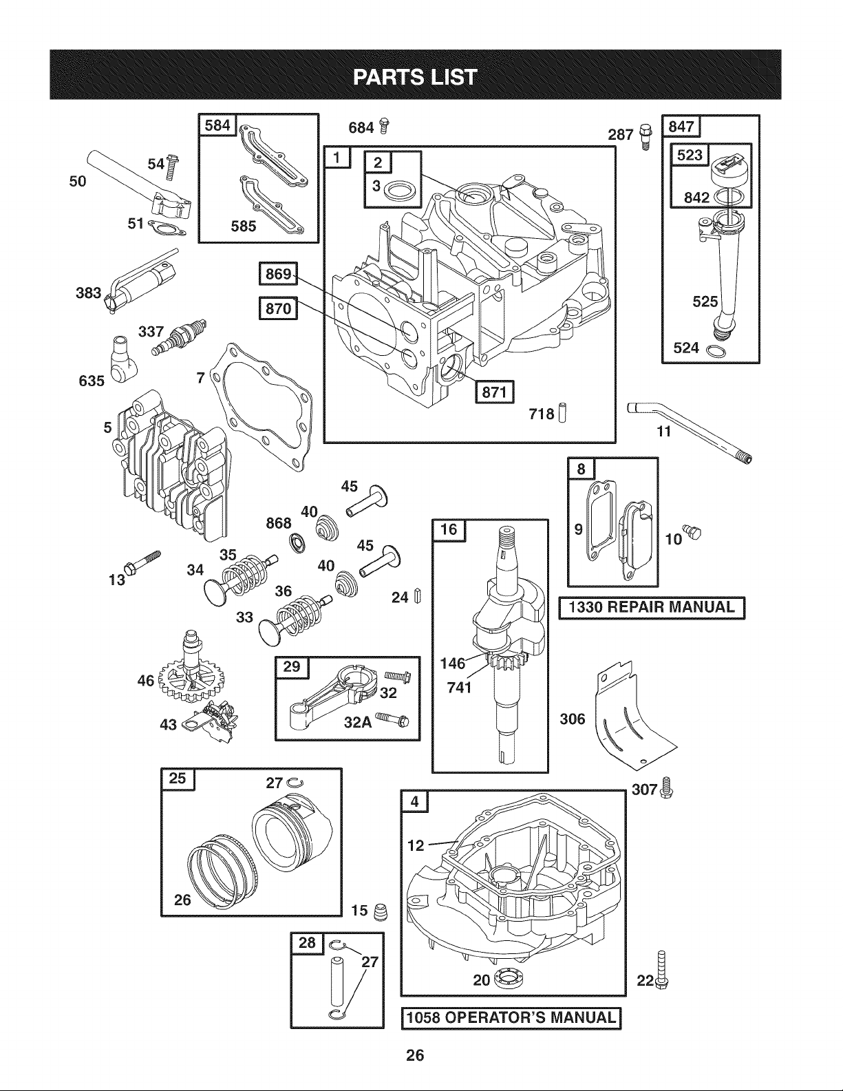
Ref.No. Part No. Description
1. 697322 CylinderAssembly
2. 399269 Kit-Bushing/Seal
3. 299819S1- Seal-Oil(MagnetoSide)
4. 493279 Sump-Engine
5. 691160 Head-Cylinder
7. 6922491- Gasket-CylinderHead
8. 695250 BreatherAssembly
9. 696125 Gasket-Breather
10. 691125 Screw(BreatherAssembly)
11. 691781 Tube-Breather
12. 6922321- Gasket-Crankcase
13. 690912 Screw(CylinderHead)
15. 691680 Plug-OilDrain
16. 691455 Crankshaft
20. 3997811- Seal-Oil(PTOSide)
22. 691092 Screw(EngineSump)
23. 691992 Flywheel
24. 222698 Key-Flywheel
25. 791097 PistonAssembly(Standard)
791326 PistonAssembly(.020"Oversize)
26. 791098 RingSet-Piston(Standard)
791324 RingSet-Piston(.020"Oversize)
27. 691866 Lock-PistonPin
28. 499423 Pin-Piston
29. 499424 Rod-Connecting
32. 691664 Screw(ConnectingRod)
32A. 695759 Screw(ConnectingRod)
33. 262651S Valve-Exhaust
34. 262652S Valve-Intake
35. 691270 Spring-Valve(Intake)
36. 691270 Spring-Valve(Exhaust)
37. 694086 Guard-Flywheel
40. 692194 Retainer-Valve
43. 691997 Slinger-Governor/Oil
45. 690548 Tappet-Valve
46. 691449 Camshaft
48. 792740 Short Block
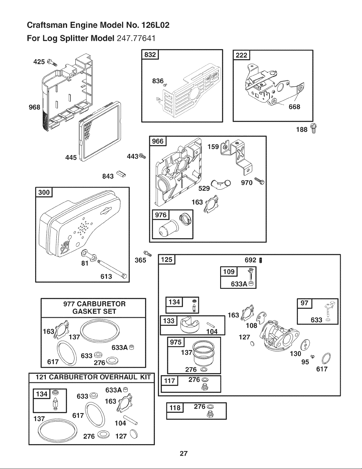
50. 794305 Manifold-Intake
51. 7943061- Gasket-intake
54. 691650 Screw(IntakeManifold)
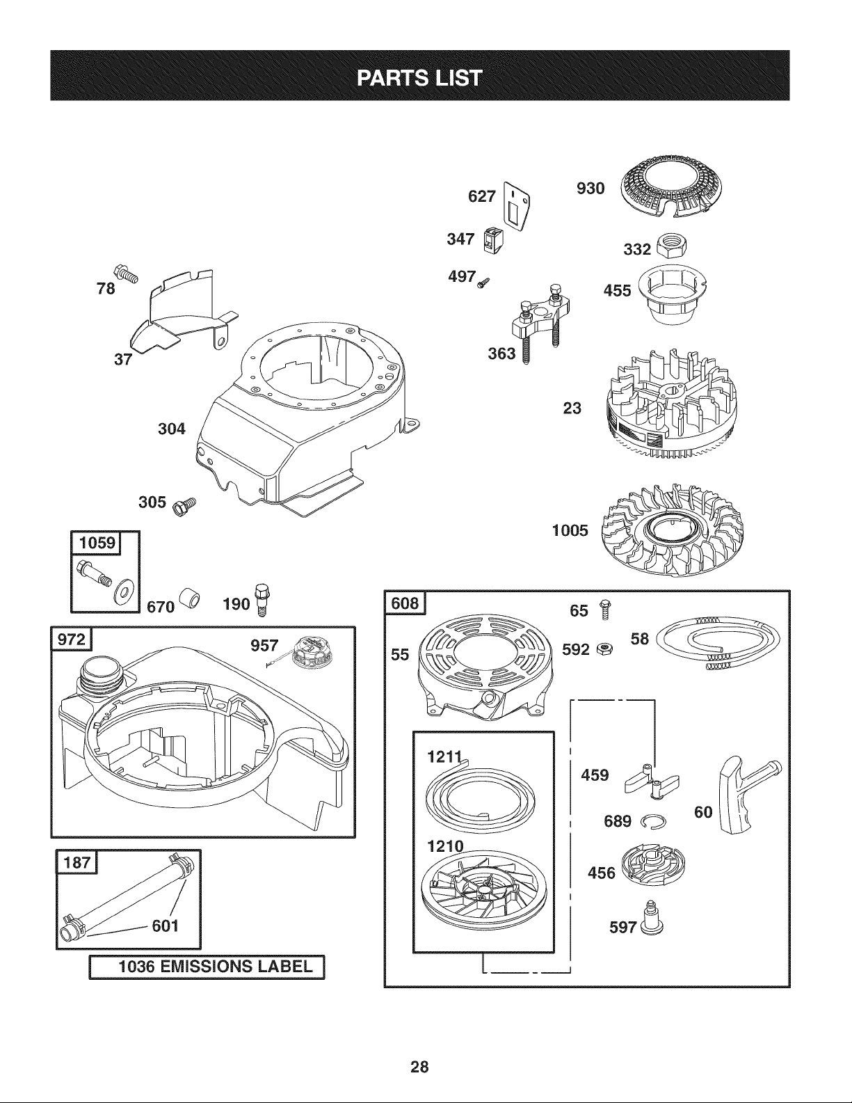
55. 691421 Housing-RewindStarter
Ref. No. Part No. Description
58. 697316 Rope-Starter(Cut to RequiredLength)
60. 281434S Grip-StarterRope
65. 690837 Screw(RewindStarter)
78. 691108 Screw(FlywheelGuard)
81. 691740 Lock-MufflerScrew
95. 691636 Screw(ThrottleValve)
97. 696565 Shaft-Throttle
104. 6912421-1- Pin-FloatHinge
108. 691182 Valve-Choke
109. 498593 Shaft-Choke
117. 498981 Jet-Main(Standard)
118. 498978 Jet-Main(HighAltitude)
121. 498260 Kit-CarburetorOverhaul
125. 792253 Carburetor
127. 6944681-1- Plug-Welch
130. 696564 Valve-Throttle
133. 398187 Float-Carburetor
134. 3981881-1- Valve-Needle/Seat
137. 6939811-1-* Gasket-FloatBowl
159. 691753 Bracket-AirCleanerPrimer
163. 272653St*it Gasket-AirCleaner
187. 791766 Line-Fuel(Cutto RequiredLength)
188. 693399 Screw(ControlBracket)
190. 690940 Screw(FuelTank)
202. 691829 Link-MechanicalGovernor
209. 790944 Spring-Governor
222. 692982 Bracket-Control
227. 690783 ControlLever-Governor
276. 2717161-1-* SealingWasher
287. 690940 Screw(DipstickTube)
300. 692038 Muffler
304. 493294 Housing-Blower
305. 691108 Screw(BlowerHousing)
306. 690450 Shield-Cylinder
307. 690345 Screw(CylinderShield)
332. 690662 Nut(Flywheel)
333. 802574 Armature-Magneto
334. 691061 Screw(ArmatureMagneto)
337. 802592S Plug-Spark
347. 691396 Switch-Rocker
356. 693010 Wire-Stop
30
Craftsman Engine Model No. 126L02
For Log Splitter Model 247.77641
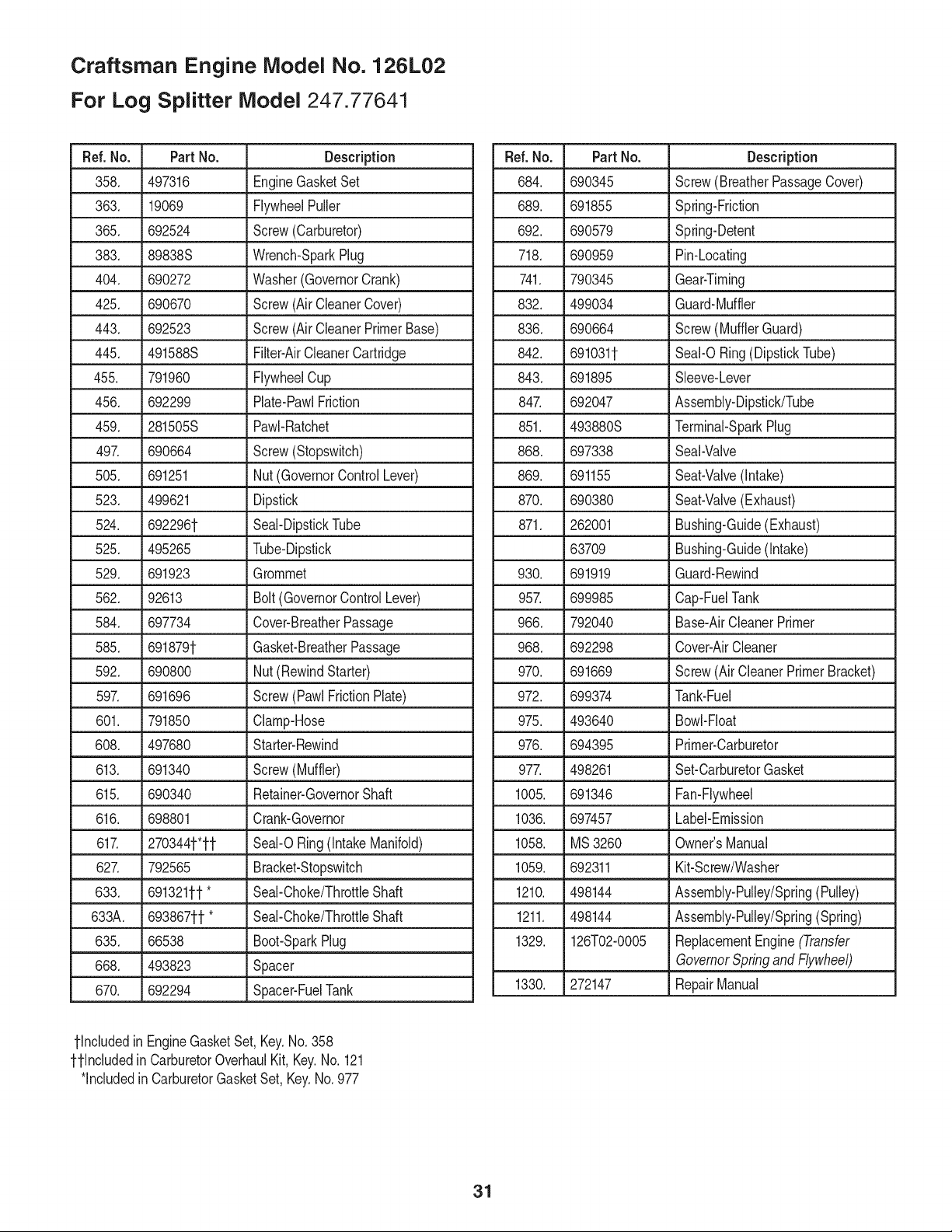
Ref. No. Part No. Description
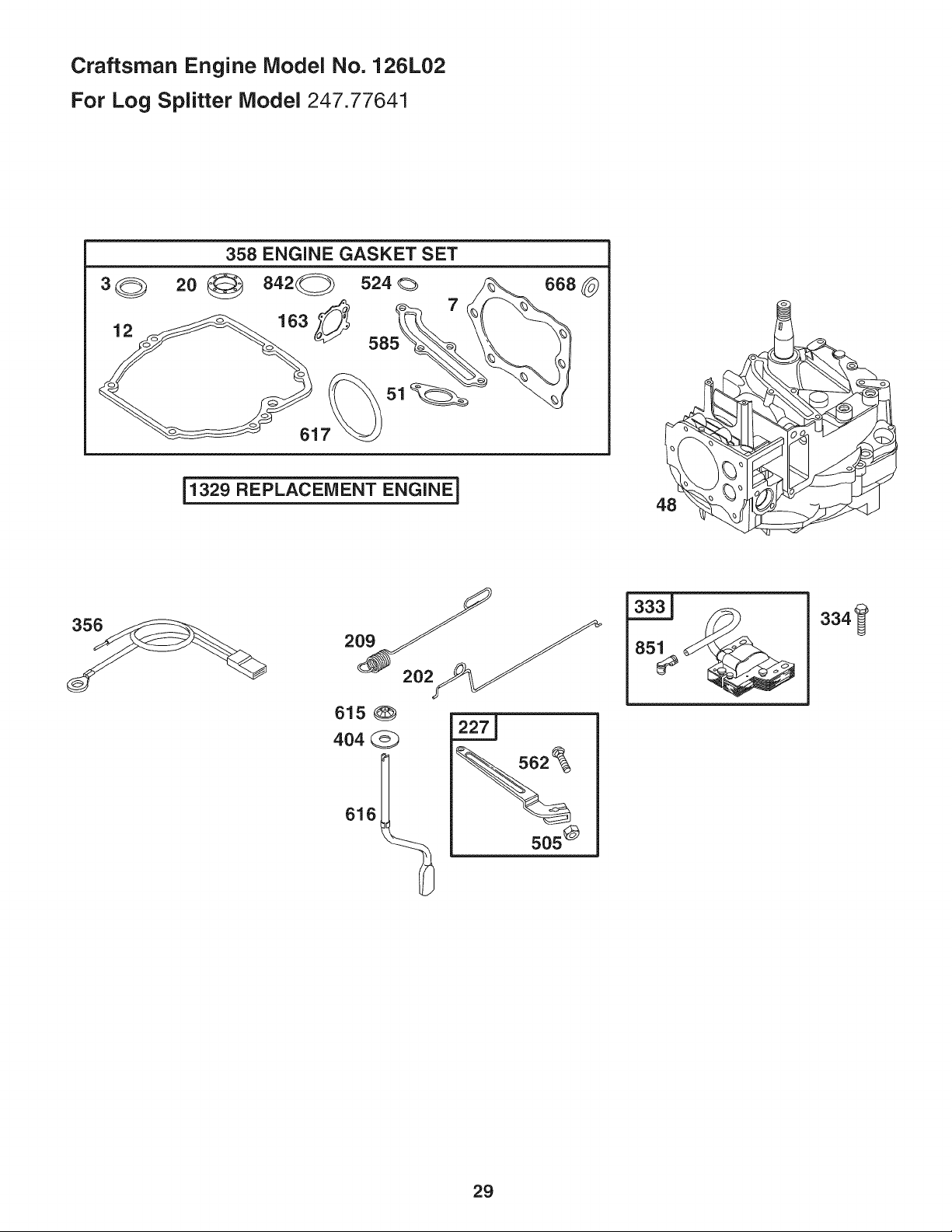
358. 497316 EngineGasketSet
363. 19069 FlywheelPuller
365. 692524 Screw(Carburetor)
383. 89838S Wrench-SparkPlug
404. 690272 Washer(GovernorCrank)
425. 690670 Screw(AirCleanerCover)
443. 692523 Screw(AirCleanerPrimerBase)
445. 491588S Filter-AirCleanerCartridge
455. 791960 FlywheelCup
456. 692299 Plate-PawlFriction
459. 281505S PawI-Ratchet
497. 690664 Screw(Stopswitch)
505. 691251 Nut(GovernorControlLever)
523. 499621 Dipstick
524. 6922961- Seal-DipstickTube
525. 495265 Tube-Dipstick
529. 691923 Grommet
562. 92613 Bolt(GovernorControlLever)
584. 697734 Cover-BreatherPassage
585. 6918791- Gasket-BreatherPassage
592. 690800 Nut(RewindStarter)
597. 691696 Screw(PawlFrictionPlate)
601. 791850 Clamp-Hose
608. 497680 Starter-Rewind
613. 691340 Screw(Muffler)
615. 690340 Retainer-GovernorShaft
616. 698801 Crank-Governor
617. 2703441-'1-1- SeaI-ORing(intakeManifold)
627. 792565 Bracket-Stopswitch
633. 6913211-1-* Seal-Choke/ThrottleShaft
633A. 6938671-1-* Seal-Choke/ThrottleShaft
635. 66538 Boot-SparkPlug
668. 493823 Spacer
670. 692294 Spacer-FuelTank
Ref. No. Part No. Description
684. 690345 Screw(BreatherPassageCover)
689. 691855 Spring-Friction
692. 690579 Spring-Detent
718. 690959 Pin-Locating
741. 790345 Gear-Timing
832. 499034 Guard-Muffler
836. 690664 Screw(MufflerGuard)
842. 6910311- SeaI-ORing(DipstickTube)
843. 691895 Sleeve-Lever
847. 692047 Assembly-Dipstick/Tube
851. 493880S Terminal-SparkPlug
868. 697338 Seal-Valve
869. _691155 Seat-Valve (intake)
870. 690380 Seat-Valve(Exhaust)
871. 262001 Bushing-Guide(Exhaust)
63709 Bushing-Guide(intake)
930. 691919 Guard-Rewind
957. 699985 Cap-FuelTank
966. 792040 Base-AirCleanerPrimer
968. 692298 Cover-AirCleaner
970. 691669 Screw(AirCleanerPrimerBracket)
972. 699374 Tank-Fuel
975. 493640 Bowl-Float
976. 694395 Primer-Carburetor
977. 498261 Set-CarburetorGasket
1005. 691346 Fan-Flywheel
1036. 697457 Label-Emission
1058. MS3260 Owner'sManual
1059. 692311 Kit-Screw/Washer
1210. 498144 Assembly-Pulley/Spring(Pulley)
1211. 498144 Assembly-Pulley/Spring(Spring)
1329. 126T02-0005 ReplacementEngine(Transfer
GovernorSpringand Flywheel)
1330. 272147 RepairManual
1-Includedin EngineGasketSet,Key.No.358
1-1-IncludedinCarburetorOverhaulKit,Key.No.121
*includedinCarburetorGasketSet,Key.No.977
31
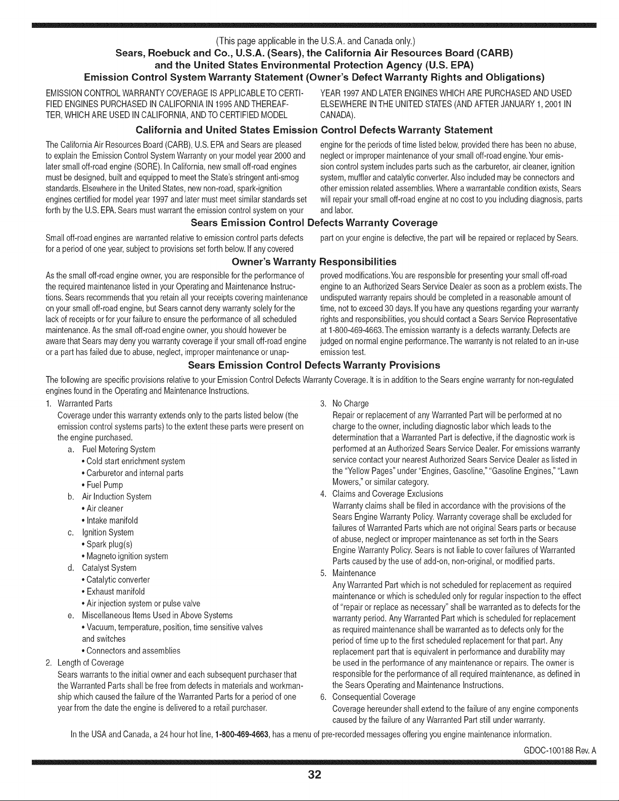
(Thispageapplicableinthe U.S.A.and Canadaonly.)
Sears, Roebuck and Co., U.S.A. (Sears), the California Air Resources Board (CARD)
and the United States Environmental Protection Agency (U.S. EPA)
Emission Control System Warranty Statement (Owner's Defect Warranty Rights and Obligations)
EMISSIONCONTROLWARRANTYCOVERAGEISAPPLICABLETO CERTI-
FIEDENGINESPURCHASEDINCALIFORNIAIN1995ANDTHEREAF-
TER,WHICHARE USEDINCALIFORNIA,ANDTO CERTIFIEDMODEL
California and United States Emission
The CaliforniaAir ResourcesBoard(CARD),U.S.EPAand Searsare pleased
to explainthe EmissionControlSystemWarrantyon your modelyear2000and
latersmalloff-roadengine(SORE).In California,newsmall off-roadengines
mustbe designed,builtand equippedto meetthe State'sstringentanti-smog
standards.Elsewherein the UnitedStates, newnon-road,spark-ignition
enginescertifiedfor modelyear 1997and latermustmeetsimilar standardsset
forth bythe U.S.EPA.Sears mustwarranttheemissioncontrolsystemon your
YEAR 1997AND LATERENGINESWHICHARE PURCHASEDANDUSED
ELSEWHEREIN THE UNITEDSTATES(ANDAFTERJANUARY1,2001 IN
CANADA).
Control Defects Warranty Statement
enginefor theperiodsoftime listedbelow,providedtherehas been noabuse,
neglector impropermaintenanceof your smalloff-roadengine.Youremis-
sion controlsystemincludespartssuch as thecarburetor,air cleaner,ignition
system,mufflerand catalyticconverter.Also includedmaybe connectorsand
otheremissionrelatedassemblies.Wherea warrantableconditionexists,Sears
will repairyour smalloff-roadengineat no costto you includingdiagnosis,parts
and labor.
Sears Emission Control Defects Warranty Coverage
Smalloff-roadenginesarewarrantedrelativeto emissioncontrolpartsdefects
fora periodof one year,subjectto provisionsset forth below.Ifany covered
Owner's Warranty
Asthe smalloff-roadengine owner,you are responsiblefor the performanceof
therequiredmaintenancelistedin yourOperatingand MaintenanceInstruc-
tions.Searsrecommendsthatyouretainallyourreceiptscoveringmaintenance
on yoursmalloff-roadengine,butSears cannotdenywarrantysolelyfor the
lackof receiptsor for yourfailureto ensurethe performanceof all scheduled
maintenance.As the smalloff-roadengineowner,you shouldhoweverbe
awarethat Searsmaydenyyou warrantycoverageifyour smalloff-roadengine
ora part hasfailed dueto abuse,neglect,impropermaintenanceor unap-
parton yourengineis defective,the part will be repairedorreplacedbySears.
Responsibilities
provedmodifications.Youare responsiblefor presentingyour smalloff-road
engineto an AuthorizedSearsServiceDealeras soonas a problemexists.The
undisputedwarrantyrepairsshouldbe completedina reasonableamountof
time,not to exceed30days.Ifyou haveany questionsregardingyourwarranty
rightsand responsibilities,you shouldcontacta SearsService Representative
at 1-800-469-4663.The emissionwarrantyis a defectswarranty.Defectsare
judgedon normalengineperformance.Thewarrantyis notrelatedto an in-use
emissiontest.
Sears Emission Control Defects Warranty Provisions
ThefollowingarespecificprovisionsrelativetoyourEmissionControlDefectsWarrantyCoverage.ItisinadditiontotheSearsenginewarrantyfornon-regulated
enginesfoundin the Operatingand MaintenanceInstructions.
1. WarrantedParts
Coverageunderthis warrantyextendsonly to the parts listedbelow (the
emissioncontrolsystemsparts)to the extentthese partswere presenton
the enginepurchased.
a. FuelMeteringSystem
• Cold start enrichmentsystem
• Carburetorand internalparts
• FuelPump
b. Air lnduction System
• Air cleaner
• Intakemanifold
c. IgnitionSystem
• Spark plug(s)
• Magnetoignitionsystem
d. CatalystSystem
• Catalyticconverter
• Exhaustmanifold
• Air injectionsystemor pulsevalve
e. MiscellaneousItemsUsedin AboveSystems
• Vacuum,temperature,position,timesensitivevalves
andswitches
• Connectorsandassemblies
2. Lengthof Coverage
Searswarrantsto the initialownerand eachsubsequentpurchaserthat
the WarrantedParts shallbe free from defects in materialsandworkman-
shipwhich causedthe failure of the WarrantedPartsfor a periodof one
yearfrom the datethe engineis deliveredto a retailpurchaser.
3. No Charge
Repairor replacementof anyWarrantedPartwill be performedat no
chargeto the owner,includingdiagnosticlabor whichleads to the
determinationthata WarrantedPartis defective,ifthe diagnosticwork is
performedat an AuthorizedSears ServiceDealer.For emissionswarranty
servicecontact yournearestAuthorizedSearsServiceDealeras listed in
the "YellowPages"under"Engines,Gasoline,""GasolineEngines,""Lawn
Mowers,"orsimilarcategory.
4. Claimsand CoverageExclusions
Warrantyclaimsshall be filed in accordancewiththe provisionsof the
Sears EngineWarrantyPolicy.Warrantycoverageshall be excludedfor
failuresof WarrantedPartswhichare notoriginal Sears partsor because
of abuse,neglector impropermaintenanceas setforth inthe Sears
EngineWarrantyPolicy.Sears is notliableto coverfailuresof Warranted
Partscausedby theuseof add-on,non-original,or modifiedparts.
5. Maintenance
Any WarrantedPart whichis notscheduledfor replacementas required
maintenanceor whichis scheduledonly for regularinspectionto the effect
of "repairor replaceas necessary"shallbe warrantedasto defectsfor the
warrantyperiod.Any WarrantedPartwhich is scheduledfor replacement
as requiredmaintenanceshallbe warrantedasto defectsonly forthe
periodof time upto the firstscheduledreplacementfor that part. Any
replacementpart that is equivalentin performanceand durabilitymay
be usedin the performanceof any maintenanceor repairs.The owneris
responsibleforthe performanceof all requiredmaintenance,as definedin
the SearsOperatingand MaintenanceInstructions.
6. ConsequentialCoverage
Coveragehereundershallextend to the failure of any engine components
caused bythe failureof any WarrantedPartstill underwarranty.
Inthe USAandCanada,a 24 hour hotline, 1-800-469-4663,has a menu of pre-recordedmessagesofferingyou enginemaintenanceinformation.
GDOC-100188Rev.A
32
Look For Relevant Emissions Durability Period and
Air index information On Your Engine Emissions Label
Engines that are certified to meet the California Air Resources Board (CARB) Tier 2 Emission Standards must
display information regarding the Emissions Durability Period and the Air Index. Sears, Roebuck and Co., U.S.A.
makes this information available to the consumer on our emission labels.
The Emissions Durability Period describes the number of hours of actual running time for which the engine is
certified to be emissions compliant, assuming proper maintenance in accordance with the Operating & Mainte-
nance Instructions. The following categories are used:
Moderate: Engine is certified to be emission compliant for 125 hours of actual engine running time.
Intermediate: Engine is certified to be emission compliant for 250 hours of actual engine running time.
Extended: Engine is certified to be emission compliant for 500 hours of actual engine running time.
For example, a typical walk-behind lawn mower is used 20 to 25 hours per year. Therefore, the Emissions
Durability Period of an engine with an intermediate rating would equate to 10 to 12 years.
The Air Index is a calculated number describing the relative level of emissions for a specific engine family. The
lower the Air Index, the cleaner the engine. This information is displayed in graphical form on the emissions label.
After July 1,2000, Look For Emissions Compliance Period
On Engine Emissions Compliance Label
After July 1, 2000 certain Sears, Roebuck and Co., U.S.A. engines will be certified to meet the United States
Environmental Protection Agency (USEPA) Phase 2 emission standards. For Phase 2 certified engines, the Emis-
sions Compliance Period referred to on the Emissions Compliance label indicates the number of operating hours
for which the engine has been shown to meet Federal emission requirements.
For engines less than 225 cc displacement, Category C = 125 hours, B = 250 hours and A = 500 hours.
For engines of 225 cc or more, Category C = 250 hours, B = 500 hours and A = 1000 hours.
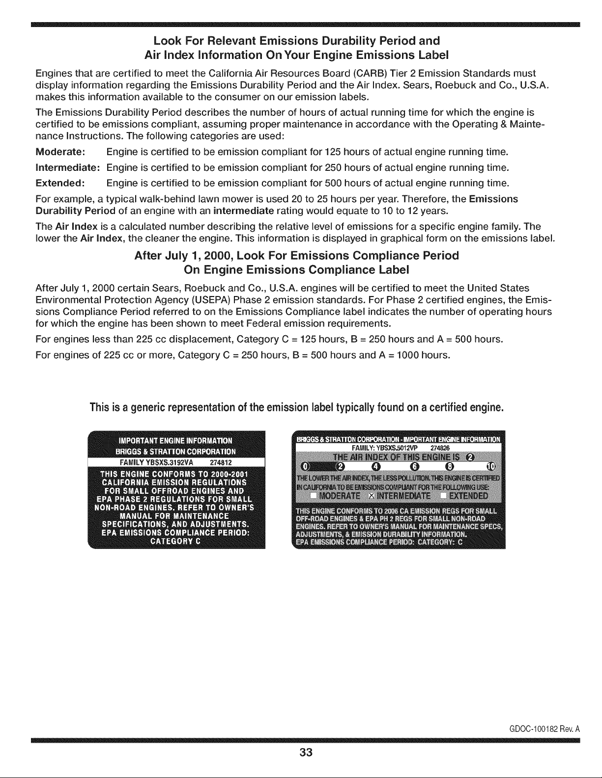
This is a generic representation of the emission label typically found on a certified engine.
FAMILYYBSXS.3192VA 274812
GDOC-100182Rev.A
33
Garantia....................................................Page34
Protecci6n.................................................Page35
Ensamble..................................................Page40-41
Funcionamiento........................................Page42-45
Servicioy ajustes......................................Page46-47
Mantenimiento..........................................Page48-50
Almacenamiento.......................................Page51
GuiDeLocalizaci6ndefallas...................Page52-54
Controlde Emisi6n...................................Page55
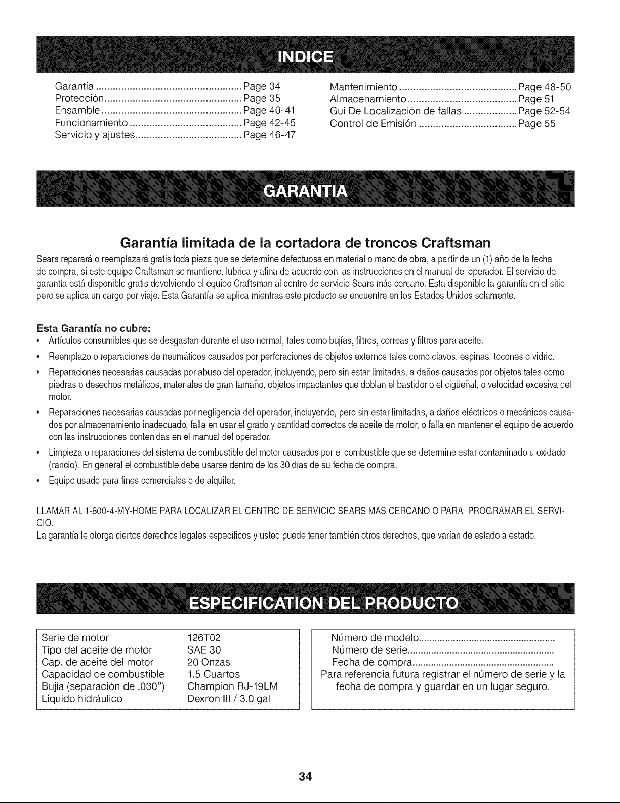
Garantfa limitada de la cortadora de troncos Craftsman
Searsreparar_,o reemplazar_,gratis todapiezaquese determinedefectuosaenmaterialo manode obra,a partirde un(1)a_ode lafecha
decompra,si esteequipoCraftsmanse mantiene,lubricay afinade acuerdocon lasinstruccionesenel manualdel operador.El serviciode
garanfiaest,.disponiblegratisdevolviendoelequipoCraftsmanal centrode servicioSearsm_.scercano.Estadisponiblela garantiaen el sitio
perose aplicaun cargopor viaje. Esta Garantiaseaplica mientrasesteproductose encuentreen los EstadosUnidossolamente.
Esta Garantia no cubre:
• Articulosconsumiblesque se desgastanduranteel uso normal,tales como bujias,filtros, correasy filtrosparaaceite.
• Reemplazoo reparacionesde neum_.ticoscausadospot perforacionesde objetosexternostalescomoclavos,espinas,toconeso vidrio.
• Reparacionesnecesariascausadasporabusodel operador,incluyendo,perosinestarlimitadas,a daSoscausadosporobjetostalescomo
piedraso desechosmet_Jicos,materialesdegrantamaSo,objetosimpactantesquedoblanel bastidoro el cig(JeSal,o velocidadexcesivadel
motor.
• Reparacionesnecesariascausadaspor negligenciadeloperador,incluyendo,perosin estarlimitadas,a da5osel_ctricoso mec_.nicoscausa-
dos pot almacenamientoinadecuado,fallaen usarel gradoy cantidadcorrectosde aceitede motor,o fallaen mantenerel equipode acuerdo
con las instruccionescontenidasen el manualdeloperador.
• Limpiezao reparacionesdel sistemade combustibledel motorcausadospor el combustibleque se determineestarcontaminadou oxidado
(rancio).Engeneralel combustibledebeusarsedentrode los30 dias de su fechade compra.
• Equipousadoparafinescomercialeso de alquiler.
LLAMARAL 1-800-4-MY-HOMEPARALOCALIZARELCENTRODESERVICIOSEARSMASCERCANO0 PARA PROGRAMARELSERVl-
ClO.
Lagarantiale otorgaciertosderechoslegalesespecificosy ustedpuedetenettambi_notrosderechos,quevariande estadoa estado.
Serie de motor
Tipo del aceite de motor
Cap. de aceite del motor
Capacidad de combustible
Bujfa (separaci6n de .030")
Lfquido hidr,_ulico
126T02
SAE 30
20 Onzas
1.5 Cuartos
Champion RJ-19LM
Dexron III/3.0 gal
NOmero de modelo ....................................................
N0mero de serie ........................................................
Fecha de compra ......................................................
Para referencia futura registrar el nOmero de serie y la
fecha de compra y guardar en un lugar seguro.
34
Felicitacionespor haberrealizadounaadquisici6ninteligente.El
productoCraftsman@queha adquiridoest_dise_adoy fabricado
parabrindarrnuchosa_osde funcionarnientoconfiable.Perocorno
todoslos productosa vecespuederequerirde reparaciones.Esen
esernornentocuandoel disponerde unAcuerdode protecci6npara
reparacionesle puedeahorrardineroy problernas.
A continuaci6nsedetallanlos puntosincluidosen el Acuerdo:
• Servicio experto prestadopornuestros10,000especialistasen
reparacionesprofesionales
• Servicio ilirnitadosin cargopara laspiezasy la rnanode obra en
todaslas reparacionescubiertas
• Reernplazodel productohasta 1500d61aressi no es posible
repararel productocubierto
• Descuentode 10%del precionormaldel servicioy delas piezas
relacionadascon el rnisrnoque no est_ncubiertasporel acuerdo;
adern&s,10%del precionormalde laverificaci6nde rnanten-
irnientopreventivo
• Ayudar_pida pot tel_fono- IoIlarnarnosResoluci6nR_pida- el
apoyotelef6nicode unCharnuscaal representante.Pienseen
nosotroscornoel manual"de undue_ohablador."
Unavezadquiridoel Acuerdo,puedeprograrnarel serviciocon
tan s61orealizarunaIlarnadatelef6nica.PuedeIlarnaren cualquier
mornentodeldia o de la nocheo prograrnarun servicioen linea.
ElAcuerdode Protecci6nde Reparaci6nes unacornprasin riesgo.
Siustedanulaporalgunaraz6nduranteel periodode garantiade
producto,proporcionarernosun reernbolsoIleno.O,un reernbolso
prorrateadoen cualquiermornentodespu_sdel periodode garantia
de productoexpira, iAdquieraboysu acuerdode protecci6npara
reparaciones!
Seaplican deterrninadaslimitaciones y exclusiones.Paraobtener
inforrnaci6nadicional y preciosen los Estados UnidosIlarne al
1-800-827-6655.
El*Coverage en Canad_variaen algunosarticulos. Paradetalles
Ilenosla IlarnadaCharnuscaCanad_en 1-800-361-6665.
Servicio de instalaci6nde Sears
Sideseasolicitarla instalaci6nprofesionalde Searsde aparatos
dorn_sticos,dispositivosparaabrirportones,calentadoresde agua
y otrosarficulosdorn_sticosirnportantes,en los EstadosUnidoso
Canad_Ilarneal 1-800-4-MY-HOME®.
35
_ DVERTENCIA: La presencia de este s[mbolo indica que se trata de instrucciones importantes
de seguridad que se deben respetar para evitar poner en peligro su seguridad personal y/o
material y la de otras personas. Lea y siga todas las instrucciones de este manual antes de poner
en funcionamiento esta m_quina. Si no respeta estas instrucciones puede provocar lesiones
personales. Cuando vea este s[mbolo, iTENGA EN CUENTA LAS ADVERTENCIAS!
PROPOSICION 65 de California "_
J
_ DVERTENCIA: El escape del motor de este producto, algunos de sus componentes y
algunos componentes del veh[culo contienen o liberan sustancias qu[micas que el estado de
California considera que pueden producir c_ncer, defectos de nacimiento u otros problemas
reproductivos.
PEUGRO: Esta m_quina est_ diser_ada para set utilizada respetando las normas de seguridad
_ ontenidas en este manual. AI igual que con cualquier tipo de equipo motorizado, un descuido o
error pot parte del operador puede producir lesiones graves. Esta m_quina es capaz de amputar
manos y pies y de arrojar objetos con gran fuerza. De no respetar las instrucciones de seguridad
siguientes se pueden producir lesiones graves o la muerte.
Capa¢itaci6n 9.
1. Lea, entienda y cumpla todas las instrucciones incluidas en la
m_quina yen el(los) manual(es) antes de intentar realizar el
montaje de la unidad y utilizarla. Guarde este manual en un
lugar seguro para consultas futuras y peri6dicas, asi como para
solicitar repuestos.
2. Familiaricese con todos los controles y con el uso adecuado
de los mismos. Sepa c6mo detener la m_quina y desactivar los
controles r_pidamente.
3. No permita nunca que los niEos menores de 16 ahos utilicen
esta m_quina. Los niEos de 16 aEos en adelante deben
leery entender las instrucciones de operaci6n y normas de
seguridad contenidas en este manual yen la m_quina y deben
ser entrenados y supervisados por un adulto.
4. Nunca permita que los adultos operen esta m_quina sin recibir 10.
antes la instrucci6n apropiada.
5. Muchos accidentes ocurren cuando m_s de una persona hace
funcionar la m_quina. Si un pe6n Io est_ ayudando a cargar los
troncos, nunca active el control hasta que el pe6n se encuentre
pot Io menosa 10 pies de distancia de la m_quina.
6. Mantenga a los transeuntes, ayudantes, mascotas y
niEos al menos a 20 pies de la m_quina mientras est_ en
funcionamiento.
7. Nunca permita que ninguna persona se desplace en la
m_quina.
8. Nunca traslade cargas en esta m_quina.
Las m_quinas rompetroncos hidr_ulicas desarrollan altas
presiones de fluido durante el funcionamiento. Si sale fluido
a trav6s de la abertura de un orificio de pasador el mismo
puede penetrar en la piel y causarle envenenamiento de la
sangre, gangrena o la muerte. Preste atenci6n a las siguientes
instrucciones en todo momento:
a.
b.
No controle las fugas con la mano.
No opere la m_quina si las mangueras, los accesorios o
los tubos est_n deshilachados, enroscados, agrietados o
dahados.
c. Detenga el motor y libere la presidn del sistema
hidr_ulico antes de cambiar o ajustar los accesorios,
mangueras, tubos u otros componentes del sistema.
d. No ajuste los valores de presi6n de la bomba o v_lvula.
Las fugas se pueden detectar pasando un cart6n o madera
sobre el _rea sospechosa, usando guantes de protecci6n y
anteojos de seguridad. Fijese si el cart6n o la madera pierden
color.
11. Si es lastimado por un escape de fluido, consulte a un m_dico
de inmediato. Si no se administra tratamiento m_dico
adecuado inmediatamente se puede producir una infecci6n o
reacci6n grave.
12. Mantenga la zona del operador y el _rea adyacente
despejadas, para poder estar parado con firmeza y seguridad.
13. Si la m_quina est_ equipada con un motor de combusti6n
interna y existe la intenci6n de usarla cerca de un terreno
agreste cubierto de bosque, arbustos o pasto, el escape de la
misma debe estar provisto de un amortiguador de chispas.
Asegurese de respetar todos los c6digos locales, estatales y
federales aplicables. Lleve el equipamiento adecuado para
combatir incendios.
14.
Esta m_quina se debe utilizar unicamente para cortar madera,
no la use con ningun otto propdsito.
36
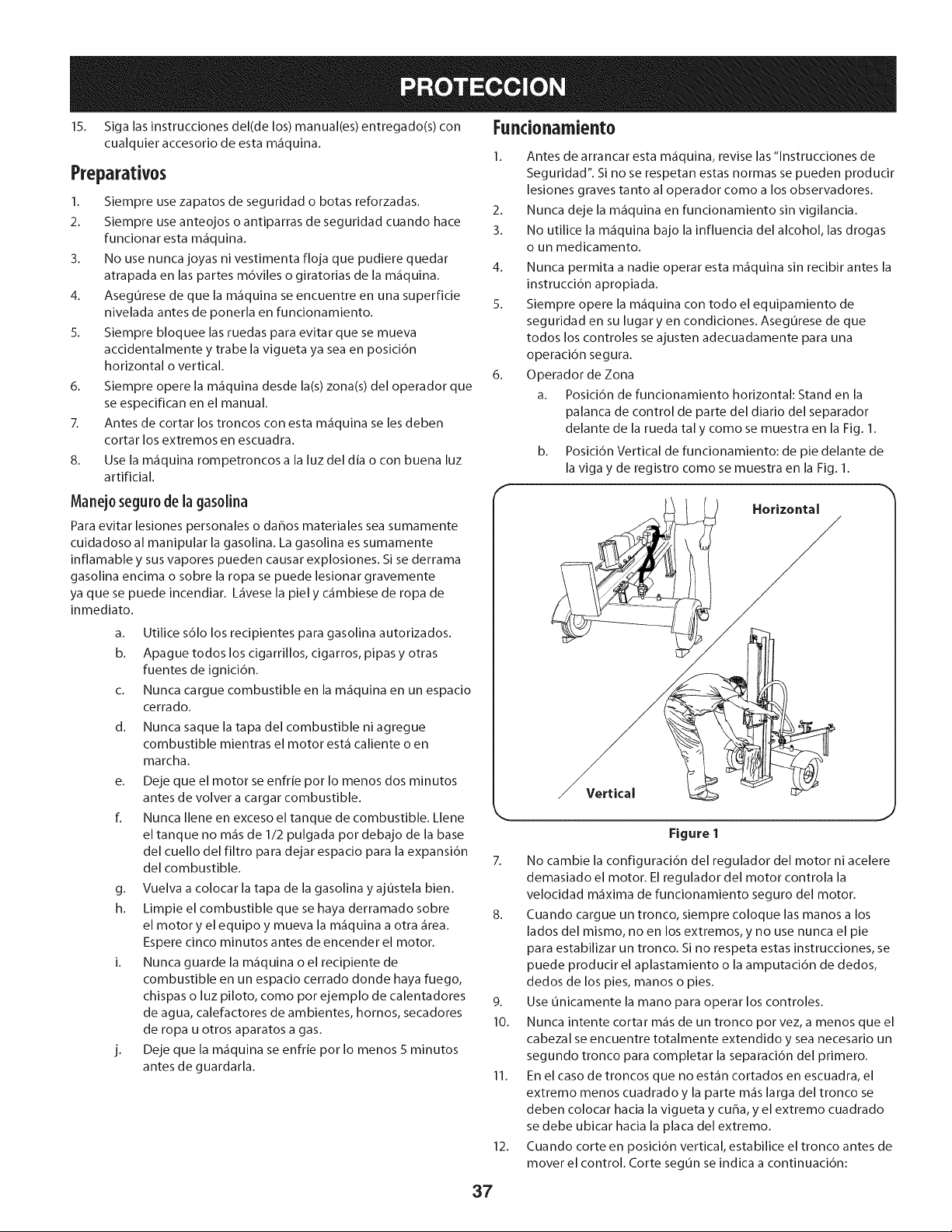
15. Siga las instrucciones del(de los) manual(es) entregado(s) con
cualquier accesorio de esta m_iquina.
Preparatives
1. Siempre use zapatos de seguridad o betas reforzadas.
2. Siempre use anteojos o antiparras de seguridad cuando hace
funcionar esta m_iquina.
3. No use nunca joyas ni vestimenta floja que pudiere quedar
atrapada en las partes m6viles o giratorias de la m_iquina.
4. Asegurese de que la m_iquina se encuentre en una superficie
nivelada antes de ponerla en funcionamiento.
5. Siempre bloquee las ruedas para evitar que se mueva
accidentalmente y trabe la vigueta ya sea en posici6n
horizontal o vertical.
6. Siempre opere la m_iquina desde la(s) zona(s) del operador que
se especifican en el manual.
7. Antes de cortar los troncos con esta m_iquina se les deben
cortar los extremes en escuadra.
8. Use la m_iquina rompetroncos a la luz del dia o con buena luz
artificial.
Fundonamiento
1. Antes de arrancar esta m_iquina, revise las "lnstrucciones de
Seguridad". Si no se respetan estas normas se pueden producir
lesiones graves tanto al operador come a los observadores.
2. Nunca deje la m_iquina en funcionamiento sin vigilancia.
3. No utilice la m_iquina bajo la influencia del alcohol, las drogas
o un medicamento.
4. Nunca permita a nadie operar esta m_iquina sin recibir antes la
instruccidn apropiada.
5. Siempre opere la m_iquina con todo el equipamiento de
seguridad en su lugar yen condiciones. Asegurese de que
todos los controles se ajusten adecuadamente para una
operacidn segura.
6. Operador de Zona
a. Posicidn de funcionamiento horizontal: Stand en la
palanca de control de parte del diario del separador
delante de la rueda tal y come se muestra en la Fig. 1.
b. Posicidn Vertical de funcionamiento: de pie delante de
la viga y de registro come se muestra en la Fig. 1.
Manej0 segur0 de la gas01ina
Para evitar lesiones personales o daEos materiales sea sumamente
cuidadoso al manipular la gasolina. La gasolina es sumamente
inflamable y sus vapores pueden causar explosiones. Si se derrama
gasolina encima o sobre la ropa se puede lesionar gravemente
ya que se puede incendiar. L_ivese la piel y c_imbiese de ropa de
inmediato.
a. Utilice s61o los recipientes para gasolina autorizados.
b. Apague todos los cigarrillos, cigarros, pipas y otras
fuentes de ignici6n.
c. Nunca cargue combustible en la m_iquina en un espacio
cerrado.
d. Nunca saque la tapa del combustible niagregue
combustible mientras el motor est,1 caliente o en
marcha.
e. Deje que el motor se enfrie per Io menos dos minutes
antes de velvet a cargar combustible.
fl Nunca Ilene en exceso el tanque de combustible. Llene
el tanque no m_is de 1/2 pulgada per debajo de la base
del cuello del filtro para dejar espacio para la expansi6n
del combustible.
g. Vuelva a colocar la tapa de la gasolina y aj0stela bien.
h. Limpie el combustible que se haya derramado sobre
el motor y el equipo y mueva la m_iquina a otra _irea.
Espere cinco minutes antes de encender el motor.
i. Nunca guarde la m_iquina o el recipiente de
combustible en un espacio cerrado donde haya fuego,
chispas o luz piloto, come per ejemplo de calentadores
de agua, calefactores de ambientes, hornos, secadores
de ropa u otros aparatos a gas.
j. Deje que la m_iquina se enfrie per Io menos 5 minutes
antes de guardarla.
Horizontal
Vertical
Figure 1
7. No cambie la configuraci6n del regulador del motor ni acelere
demasiado el motor. El regulador del motor controla la
velocidad m_ixima de funcionamiento seguro del motor.
8. Cuando cargue un tronco, siempre coloque las manes a los
lades del mismo, no en los extremes, y no use nunca el pie
para estabilizar un tronco. Si no respeta estas instrucciones, se
puede producir el aplastamiento o la amputaci6n de dedos,
dedos de los pies, manes o pies.
9. Use unicamente la mane para operar los controles.
10. Nunca intente cortar m_is de un tronco per vez, a menos que el
cabezal se encuentre totalmente extendido y sea necesario un
segundo tronco para completar la separaci6n del primero.
11. En el case de troncos que no est_in cortados en escuadra, el
extreme menos cuadrado y la parte m_is larga del tronco se
deben colocar hacia la vigueta y cuba, y el extreme cuadrado
se debe ubicar hacia la placa del extreme.
12. Cuando corte en posici6n vertical, estabilice el tronco antes de
mover el control. Corte segun se indica a continuaci6n:
37
a. Coloque el tronco en la placa del extremo y girelo hasta
que se incline contra la vigueta y quede estable.
b. Cuando corte troncos muy grandes o desparejos, el
tronco se debe estabilizar con cu_as de madera o
madera cortada entre el tronco y la placa del extremo o
el suelo.
12. Mantenga los dedos alejados de cualquier hendidura
que se abra en el tronco mientras realiza el cortado. Estas
separaciones se pueden cerrar con rapidezy atrapar o amputar
dedos.
13. Mantenga limpia el _irea de trabajo. Retire inmediatamente la
madera cortada que quede alrededor de la m_iquina para no
tropezarse con la misma.
14. Nunca mueva la m_fiquina mientras est,1 en funcionamiento.
15. Esta m_fiquina no se debe remolcar en ninguna calle, ruta o
camino p0blico sin verificar los requisitos aplicables a los
vehiculos seg0n las reglamentaciones federales, estatales o
locales que se encuentren en vigencia. Cualquier autorizaci6n
o modificaci6n que se deba realizar, pot ejemplo, en relaci6n
con luces traseras, etc., es responsabilidad exclusiva del
comprador. Si en su estado se exige una "Declaraci6n de
Origen", consulte con su distribuidor local.
16. No remolque la m_iquina pot encima de las 45 mph.
17. Vea la secci6n 'Transporte de la m_iquina rompetroncos' de
este manual para consultar las instrucciones de remolque
adecuadas despu_s de haber cumplimentado todos los
requisitos federales, locales o estatales.
Mantenimiento y alrnacenarniento
1. Detenga el motor, desconecte la bujia y haga masa contra el
motor antes de limpiar o inspeccionar la m_iquina.
2. Detenga el motor y libere la presi6n del sistema hidr_iulico
antes de reparar o ajustar los accesorios, mangueras, tubos u
otros componentes del sistema.
3. Para evitar incendios, limpie la suciedad y grasa de las _ireas
del motor y del silenciador. Si el motor est,1 equipado con
un silenciador con amortiguador de chispas, limpielo e
inspecci6nelo regularmente segun las instrucciones de los
fabricantes. Reempl_icelo si est,1 da_ado.
4. Peri6dicamente controle que todas las tuercas y pernos,
abrazaderas de mangueras y accesorios hidr_iulicos est_n
ajustados, para verificar que el equipo se encuentra en
condiciones de trabajo seguras.
5. Controle todos los protectores y escudos de seguridad para
verificar que se encuentren en posici6n adecuada. Nunca
opere la m_iquina si se han retirado los protectores o escudos
de seguridad u otros dispositivos de protecci6n.
6. La wilvula de descarga de presi6n viene preconfigurada de
f_ibrica. No la ajuste.
7. No intente nunca mover la m_iquina en terreno en pendiente o
desparejo sin un vehiculo de remolque o sin ayuda adecuada.
8. Pot su seguridad, cambie todas las piezas dahadas o
9.
10.
desgastadas inmediatamente utilizando unicamente equipo
del fabricante original ('OEM'). "La utilizaci6n de piezas que no
cumplen con las especificaciones de equipos originales puede
tenet como resultado un rendimiento inadecuado y puede
poner en riesgo la seguridad".
No modifique esta m_iquina de ningun modo; si se realizan
modificaciones tales como agregado de una cuerda o
alargador a la manija de control, o el aumento del ancho o
la altura de la cuba, se pueden producir lesiones personales
graves.
Segun la Comisi6n de Seguridad de Productos para el
Consumidor de los Estados Unidos (CPSC) y la Agencia de
Protecci6n Ambiental de los Estados Unidos (EPA), este
producto tiene una vida dtilmedia de siete (7) ahos 6 130 horas
de funcionamiento. AI finalizar la vide dtilmedia, adquiera una
m_iquina nueva o haga inspeccionar anualmente esta unidad
pot un distribuidor de servicio autorizado para cerciorarse de
que todos los sistemas mec_inicos y de seguridad funcionan
correctamente y no tienen excesivo desgaste. Si no Io hace,
pueden producirse accidentes, lesiones o la muerte.
Amortiguadordechispas
_ DVERTENCIA: Esta m_fiquina est,1 equipada con un
motor de combusti6n interna y no debe set utilizada en
un terreno agreste cubierto por bosque, malezas o
hierba ni cerca del mismo excepto que el sistema de
escape del motor est_ equipado con un amortiguador
de chispas que cumpla con las leyes locales o estatales
correspondientes (en caso de haber).
Si se utiliza un amortiguador de chispas el operador Io debe
mantener en condiciones de uso adecuadas. En el Estado de
California las medidas anteriormente mencionadas son exigidas pot
ley (Articulo 4442 del C6digo de Recursos Publicos de California).
Es posible que existan leyes similares en otros estados. Las leyes
federales se aplican en territorios federales.
Puede conseguir el amortiguador de chispas para el silenciador a
trav_s de su distribuidor de mantenimiento de motores autorizado
m_is cercano o poni_ndose en contacto con el departamento de
servicios, Apartado Postal 361131 Cleveland, Ohio 44136-0019.
r
ADVERTENCIA: Su responsabilidad--Restrinja el uso de esta m_fiquina motorizada alas personas que lean, comprendan y
respeten las advertencias e instrucciones que figuran en este manual yen la m_iquina.
GUARDEESTASINSTEUCCIONES
;38
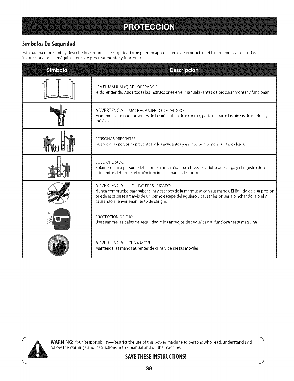
Simbolos DeSeguridad
Esta p_gina representa y describe los simbolos de seguridad que pueden aparecer en este producto. Leido, entienda, y siga todas las
instrucciones en la m_quina antes de orocurar montar y funcionar.
° "---_'_'-_7 LEA EL MANUAL(S) DEL OPERADOR
leido, entienda, y siga todas las instrucciones en el manual(s) antes de procurar montar y funcionar
'11
ADVERTENCIA-- MACHACAMIENTO DE PELIGRO
Mantenga las manos ausentes de la cuba, placa de extremo, parta en parte las piezas de madera y
m6viles.
PERSONAS PRESENTES
Guarde alas personas presentes, a los ayudantes y a ni_os pot Io menos 10 pies lejos.
SOLOOPERADOR
Solamente una persona debe funcionar la m_quina a la vez. Eladulto que carga y el registro de los
asimientos deben serel qui6n funciona la manija de control.
ADVERTENCIA-- LfQUIDO PRESURIZADO
Nunca compruebe para saber si hay escapes de la manguera con sus manos. El liquido de alta presi6n
puede escaparse a trav6s de un perno escape del agujero y causar lesi6n seria pinchando la piel y
causando el envenenamiento de sangre.
PROTECCION DE OJO
Use siempre las galas de seguridad o los anteojos de seguridad al funcionar esta m_quina.
ADVERTENCIA-- CUNA MOVlL
Mantenga las manos ausentes de cuba y de piezas m6viles.
WARNING: Your Responsibility--Restrict the use of this power machine to persons who read, understand and
follow the warnings and instructions in this manual and on the machine.
SAVETHESEINSTRUCTIONS!
39
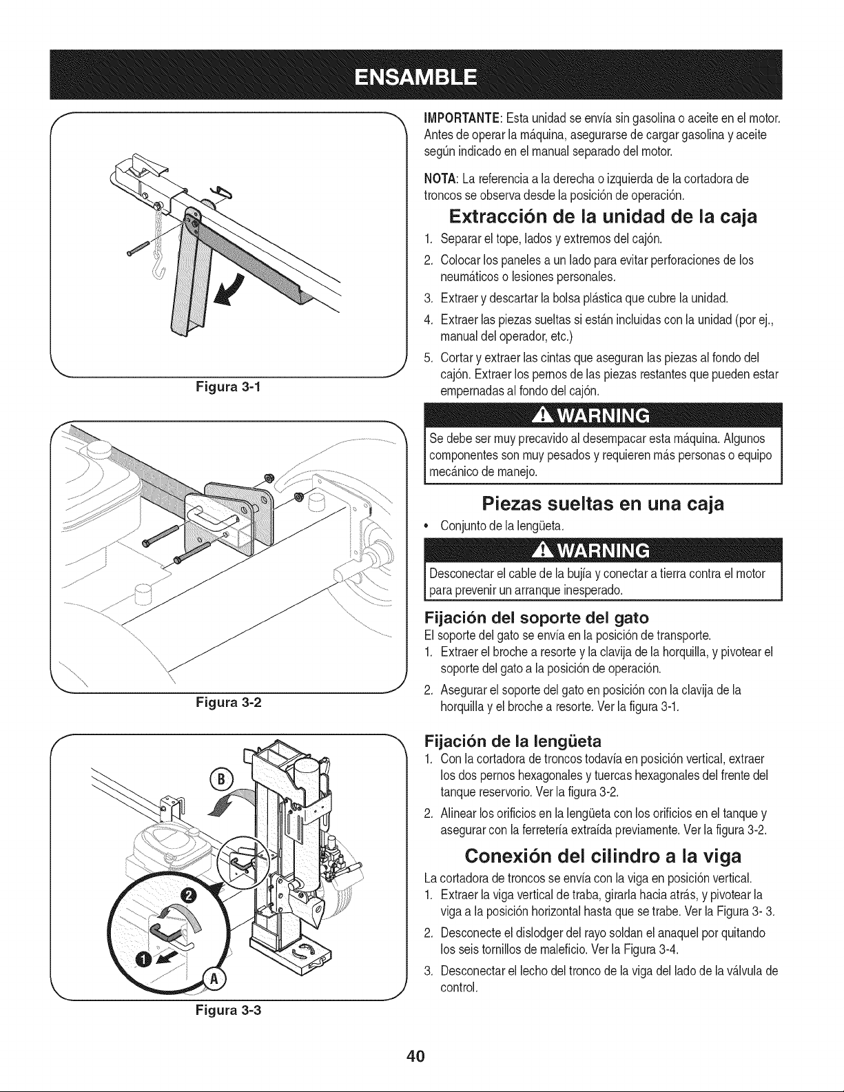
Figura 3=1
_J
IMPORTANTE:Esta unidadse enviasingasolinao aceite en el motor.
Antesde operarla rn&quina,asegurarsede cargargasolinay aceite
segQnindicadoen el manualseparadodel motor.
\
Figura 3-2
NOTA:La referenciaa la derechao izquierdadela cortadorade
troncosse observadesde laposici6ndeoperaci6n.
Extraccion de la unidad de la caja
1. Separarel tope,ladosy extrernosdelcaj6n.
2. Colocarlos panelesa un ladoparaevitarperforacionesde los
neurn_ticoso lesionespersonales.
3. Extraery descartarla bolsapl_sticaque cubrela unidad.
4. Extraerlaspiezas sueltassi est_nincluidascon la unidad(porej.,
manualdel operador,etc.)
5. Cortar y extraerlas cintasque aseguranlas piezasalrondodel
caj6n.Extraerlos pernosde las piezasrestantesque puedenestar
ernpernadasal rondodel caj6n.
Se debeser rnuyprecavidoaldesernpacarestarnAquina.Algunos
cornponentesson rnuypesadosy requierenrn_spersonaso equipo
rnec_nicode rnanejo.
Piezas sueltas en una caja
• Conjuntode la leng_eta.
Desconectarel cabledela bujiay conectara tierracontra el motor
paraprevenirunarranqueinesperado.
Fijaci6n del soporte del gato
Elsoportedelgato seenvia enla posici6nde transporte.
1. Extraerel brochea resortey la clavijade lahorquilla,y pivotearel
soportedel gatoa la posici6nde operaci6n.
2. Asegurarel soportedelgatoen posici6ncon laclavijade la
horquillay el brochea resorte.Vet lafigura3-1.
f
.J
Fijaci6n de la lengiJeta
1. Con la cortadorade troncostodaviaen posici6nvertical,extract
los dos pernoshexagonalesy tuercashexagonalesdelfrentedel
tanquereservorio.Verla figura3-2.
2. Alinear losorificiosen la lengOetacon losorificiosenel tanquey
asegurarcon la ferreteriaextraidapreviarnente.Verla figura3-2.
Cone×ion del cilindro a la viga
Lacortadorade troncosse enviacon la vigaen posici6nvertical.
1. Extraerla viga verticalde traba,girarlahaciaatr_s,y pivotearla
viga a la posici6nhorizontalhastaquese trabe.Vet la Figura3- 3.
2. Desconecteel dislodgerdel rayosoldanel anaquelporquitando
los seis tornillosde rnaleficio.Verla Figura3-4.
3. Desconectarel lechodeltroncode lavigadel ladodela v_lvulade
control.
Figura 3=3
4O

4. Levantary correrel dlindro hastael topede laviga y dentrodelos
soportessoldados.Verla Figura3-5.
5. Fijarel impulsorsobreel conjuntode la cuSay fijar a los soportes
soldadoscon la ferreteriapreviamenteextraida.
NOTA:Unavez que los seistornillosde maleficioson seaprietan,
puedehaberunhuecoleveentreel dislodgery los anaqueles
soldar_.s.Estehuecoes aceptable.
6. Volvera fijarel lechodel troncoal ladode la vigacon la v_Jvulade
control,alineandolosextremosdel lechocon las bridasde laviga.
7. Rodarla cortadorade troncosdel rondodelcaj6n.
Preparacion de la cortadora de troncos
1. Lubricarel &teade la vigadonde la cuSade cortecorre,con aceite
paramotor.(NO USARGRASA).
2. Quitela varillade aceitededep6sitoexpresada,quees Iocalizada
delantedel motorsobrelacima del tanquede dep6sito.Ver la
Figura3-6.
3. Lleneel tanquede dep6sitode DexronIII fluidode transmisi6n
autom&ticoo lOWel fluidoiAH! hidrAulico.
4. Compruebeel nivelfiuidoqueusa la varillade aceite.Vet la Figura
3-6.
NOTA:El tanquereservoriotieneuna capacidadde 3galones.
5. No sobrelleney sustituyala varillade aceiteexpresadabien. La
varillade aceitedeberia serse aprietanantesdequela cimade los
hilossea el rubor(conlacimadeltubo.
6. Si labujfatodaviano est,.desconectada,desconectarelcablede
la mismay cebar la bomba,tirandodel arranquede retrocesopara
hacergirarel motor 10vecesaproximadamente.
7. Reconectarel cablede la bujfa,arrancarel motordeacuerdocon
Arranquedel Motorenla secci6nde OPERACION.
8. Usarel mangodecontrolparaengancharlacubaa la posici6n
extremaextendiday a continuaci6nretraerlacuba.
9. Tanquede recambioa dentrode lagamaespecificadasobrela
varillade aceite.
10.Extendery retraerla cuba 12cicloscompletosparaextraerel aire
atrapadoenel sistema(elsistemaes "autopurgante").
11.Gran partedel liquidooriginal ha sidoabsorbidodentrodelcilindro
y las mangueras.Asegurarsede Ilenarel reservoriopara prevenir
unda_oextremoa la bombahidr_.ulica.La fallaen Ilenarel tanque
cancelalagarantia.
NOTA:Algode liquidopuededesbordarsedesdeel tap6ndel venti-
laderoa medidaqueel sistemase calientay el liquidoseexpandey
buscaun nivelequilibrado.
IMPORTANTE:Nooperarla cortadorade troncossinla cantidad
adecuadadeliquidode transmisi6nen el tanquereservorio.
Figura 3=4
Figura 3-5
\\\
"x
\
\
Figura 3=6
41
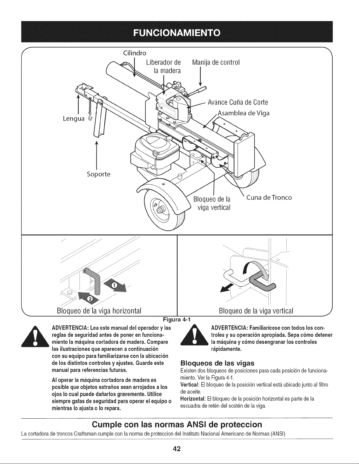
Cilindro
Liberador de Manija de control
la madera
Lengua
Avance Cuba de Corte
de Viga
1
Soporte
BIoqueo de la
viga vertical
Cuna de Tronco
Bloqueo dela viga horizontal
Figura 4-1
ADVERTENCIA:Leaestemanual del operador y las
reglasde seguridadantes de poner en funciona-
miento la m_quina cortadorade madera.Compare
las ilustracionesque apareeena continuaci6n
con su equipopara familiarizarse con la ubicaci6n
de los distintos controlesy ajustes. Guardeeste
manualpara referenciasfuturas.
AI operar la m_quina cortadorade madera es
posibleque objetos extra6osseanarrojados a los
ojos Io cual puede da6arlos gravemente.Utilice
siempregafas de seguridadpara operar el equipoo
mientras Io ajusta o Io repara.
ii
ii
BIoqueode la viga vertical
J
_ DVERTENCIA:Familiaricesecontodos los con-
troles y su operaei6n apropiada. Sepac6modetener
la m_quina y c6mo desengranar los controles
r_pidamente.
Bloqueos de las vigas
Existendos bloqueosde posicionesparacadaposici6nde funciona-
miento.Vet la Figura4-1.
Vertical:El bloqueode la posici6nverticalest_ubicadojuntoal filtro
de aceite.
Horizontal:Elbloqueode laposici6nhorizontales partede la
escuadraderetchdel sost_nde la viga.
Curnple con las normas ANS! de proteccion
LacortadoradetroncosCraftsmancumplecon la normadeprotecciondel InstitutoNacionalAmericanode Normas(ANSI)
42
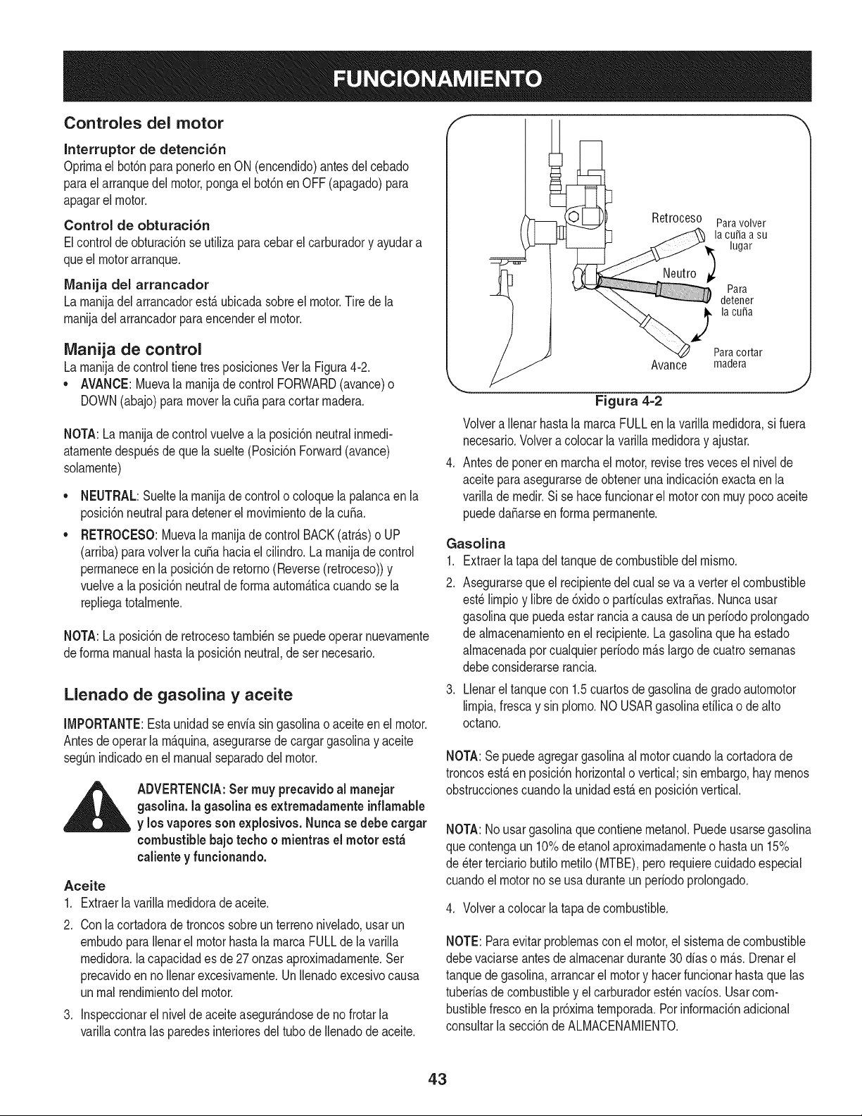
Controles del motor
Interruptor de detenci6n
Oprirnael bot6nparaponerloenON (encendido)antesdel cebado
paraelarranquedelmotor,pongael bot6nen OFF(apagado)para
apagarel motor.
Control de obturaci6n
Elcontrolde obturaci6nse utilizaparacebarel carburadory ayudara
queel motorarranque.
Manija del arrancador
La rnanijadel arrancadorest,. ubicadasobreel motor.Tirede la
rnanijadel arrancadorparaencenderel motor.
iVlanija de control
La rnanijade controltiene tresposicionesVer la Figura4-2.
• AVANCE:Muevala rnanijadecontrolFORWARD(avance)o
DOWN(abajo)paramoverla cuSaparacortarrnadera.
NOTA:La rnanijade controlvuelvea la posici6nneutralinrnedi-
atarnentedespu_sdeque lasuelte(Posici6nForward(avance)
solarnente)
NEUTRAL:Sueltela rnanijade controlo coloquela palancaen la
posici6nneutralparadetenerel rnovirnientode lacuSa.
RETROCESO:Muevala rnanijade controlBACK(atr_.s)o UP
(arriba)paravolverla cuSahaciael cilindro. La rnanijade control
perrnaneceen la posici6nde retorno(Reverse(retroceso))y
vuelvea la posici6nneutralde forrnaautorn_.ticacuandose la
repliegatotalrnente.
NOTA:La posici6nde retrocesotarnbi_nse puedeoperarnuevarnente
deforrnamanualhasta la posici6nneutral,de sernecesario.
Llenado de gasolina y aceite
IMPORTANTE:Estaunidadse enviasin gasolinao aceiteen el motor.
Antesdeoperarla rn_.quina,asegurarsede cargargasolinay aceite
segOnindicadoen el manualseparadodel motor.
__ ADVERTENCIA:Set muy precavidoal manejar
gasolina,lagasolinaes extremadamenteinflamable
y los vaporessonexplosivos.Nunca se debe cargar
combustiblebajo techo o mientras el motorest;_
calientey funcionando.
Aceite
1. Extraerla varillarnedidorade aceite.
2.
.
Conla cortadorade troncossobreun terrenonivelado,usar un
ernbudoparaIlenarel motorhastala rnarcaFULLde la varilla
rnedidora,la capacidades de 27 onzasaproxirnadarnente.Ser
precavidoen noIlenarexcesivarnente.UnIlenadoexcesivocausa
unrnalrendirnientodel motor.
Inspeccionarel nivelde aceiteasegur_.ndosede nofrotarla
varillacontralas paredesinterioresdel tubo deIlenadode aceite.
I
Retroceso Paravolver
lacu_aasu
lugar
Para
detener
i la cuba
Paracortar
Avance madera
J
Figura 4-2
Volvera Ilenarhastala rnarcaFULLenla varillarnedidora,si fuera
necesario.Volvera colocarlavarillarnedidoray ajustar.
Antesdeponeren rnarchael motor,revisetres vecesel nivelde
aceiteparaasegurarsedeobteneruna indicaci6nexactaen la
varillade rnedir.Si se hacefuncionarel motor conrnuypocoaceite
puededa_arseenforrnaperrnanente.
Gasolina
1. Extraerla tapadel tanquede combustibledel rnisrno.
2. Asegurarseque el recipientedelcual se vaa verterelcombustible
est_lirnpioy librede 6xidoo parficulasextra,as. Nuncausar
gasolinaque puedaestarranciaa causa de un periodoprolongado
de almacenarnientoen el recipiente.Lagasolinaquehaestado
alrnacenadapor cualquierperiodorn_.slargode cuatrosernanas
debeconsiderarserancia.
Llenareltanquecon 1.5cuartosde gasolinadegradoautornotor
lirnpia,frescay sin plorno.NO USARgasolinaetilica o dealto
octano.
NOTA:Sepuedeagregargasolinaal motorcuandola cortadorade
troncosest,. en posici6nhorizontalo vertical;sin embargo,hay rnenos
obstruccionescuandola unidadest,. en posici6nvertical.
NOTA:No usargasolinaque contienernetanol.Puedeusarsegasolina
quecontengaun 10%deetanolaproxirnadarnenteo hastaun 15%
de _terterciariobutilornetilo(MTBE),perorequierecuidadoespecial
cuandoel motornose usa duranteun periodoprolongado.
4. Volvera colocar la tapade combustible.
NOTE:Paraevitarproblernascon el motor,el sisternadecombustible
debevaciarseantesde alrnacenardurante30dias o rn_.s.Drenarel
tanquede gasolina,arrancarel motory hacerfuncionarhastaque las
tuberiasde combustibley elcarburadorest_nvados. Usarcom-
bustiblefrescoen la pr6xirnaternporada.Por inforrnaci6nadicional
consultarla secci6nde ALMACENAMIENTO.
43
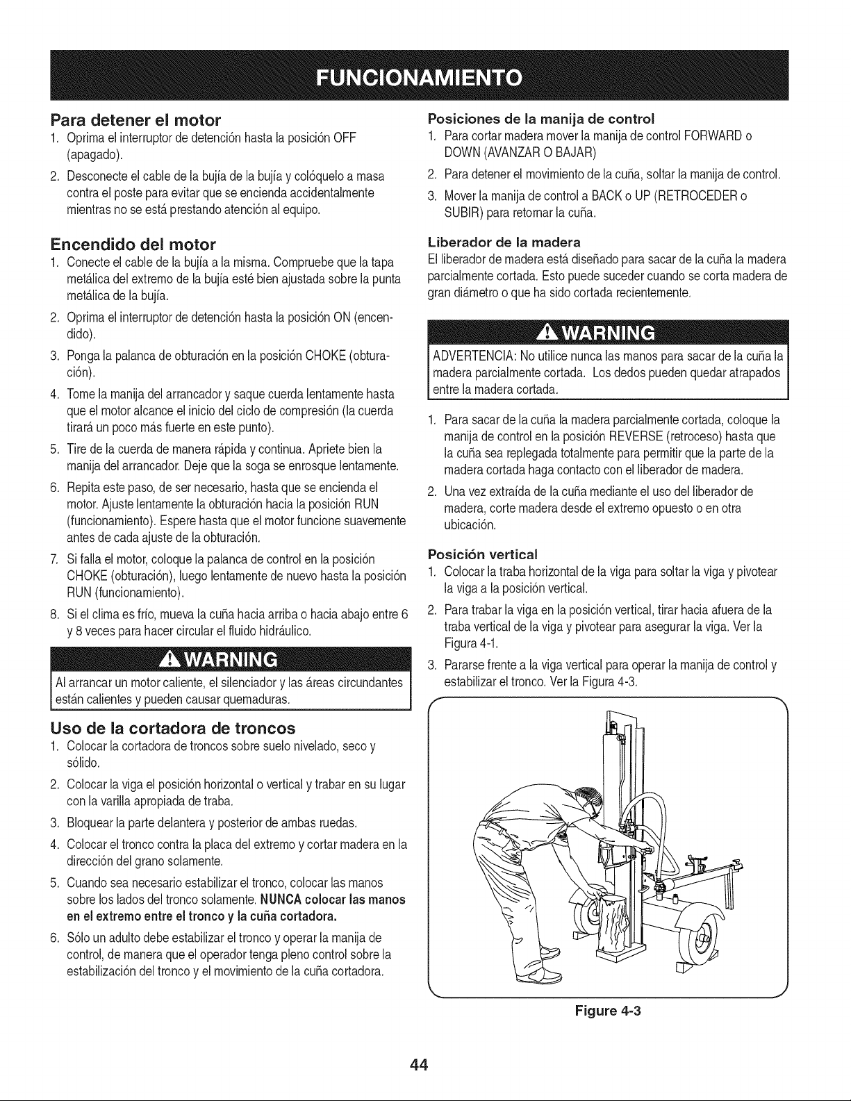
Para detener el motor
1. Oprimael interruptordedetenci6nhastala posici6nOFF
(apagado).
2. Desconecteelcable de la bujiade labujfay col6queloa masa
contrael posteparaevitarque seenciendaaccidentalmente
mientrasnose estAprestandoatencbn alequipo.
Posiciones de la manija de control
1. Paracortar maderamoverla manijade control FORWARDo
DOWN(AVANZAR0 BAJAR)
2. Paradetenerel movimientode lacuba,soltarla manijade control.
3. Moverla manijade controla BACKo UP(RETROCEDERo
SUBJR)para retornarla cuba.
Encendido del motor
1. Conecteel cablede labujfaa la misma.Compruebequela tapa
met_.licadelextremode la bujiaest_bienajustadasobrela punta
met_.licade labujia.
2. Oprimael interruptordedetenci6nhastala posici6nON(encen-
dido).
3. Pongala palancadeobturaci6nen la posici6nCHOKE(obtura-
ci6n).
4. Tomela manijadel arrancadory saquecuerdalentamentehasta
queel motoralcanceel iniciodel cido de compresi6n(lacuerda
tirar_,un pocom_.sfuerteeneste punto).
5. Tirede lacuerdade manerar@iday continua.Aprietebienla
manijadel arrancador.Dejeque la sogase enrosquelentamente.
6. Repitaeste paso,de sernecesario,hastaquese enciendael
motor.Ajustelentamentela obturaci6nhaciala posici6nRUN
(funcionamiento).Esperehastaque el motorfuncionesuavemente
antesde cadaajustede laobturaci6n.
7. Si falla el motor,coloquela palancade controlenla posici6n
CHOKE(obturaci6n),luegolentamentede nuevohastala posici6n
RUN(funcionamiento).
8. Si el climaes frio, muevala cuba haciaarribao haciaabajoentre6
y 8 vecesparahacercircularelfluidohidr_.ulico.
AIarrancarun motorcaliente,el silenciadory las _.reascircundantes
est_.ncalientesy puedencausarquemaduras.
Liberador de la madera
Eiliberadorde rnaderaest,. dise_adopara sacarde lacuba larnadera
parcialmentecortada.Estopuede sucedercuandosecorta maderade
grandi_.metroo que hasidocortada recientemente.
ADVERTENCIA:No utilicenuncalas rnanospara sacarde lacuba la
maderaparcialmentecortada. Losdedospuedenquedaratrapados
entrela maderacortada.
1. Parasacarde lacuba la maderaparcialmentecortada,coloquela
manijade controlen la posici6nREVERSE(retroceso)hastaque
la cubasea replegadatotalmenteparapermitirque lapartede la
maderacortadahagacontactocon el liberadordemadera.
2. Unavez extraidade la cubamedianteel uso del liberadorde
madera,cortemaderadesdeel extremoopuestoo en otra
ubicaci6n.
Posici6n vertical
1. Colocarla trabahorizontalde laviga para soltarla vigay pivotear
la vigaa la posici6nvertical.
2. Paratrabarla viga en laposici6nvertical,tirar haciaafuerade la
trabaverticalde laviga y pivotearparaasegurarla viga.Verla
Figura4-1.
3. Pararsefrentea la viga verticalparaoperarla manijade controly
estabilizareltronco.Ver la Figura4-3.
Uso de la cortadora de troncos
1. Colocarla cortadorade troncossobresuelonivelado,secoy
s61ido.
2. Colocarla viga el posici6nhorizontalo verticaly trabaren su lugar
con la varillaapropiadade traba.
3. Bloquearla partedelanteray posteriorde ambas ruedas.
4. Colocarel tronco contrala placadelextremoy cortarmaderaenla
direcci6ndel granosolamente.
5. Cuandosea necesarioestabilizarel tronco,colocarlas manos
sobrelos ladosdeltroncosolamente.NUNCAcolocar las manos
en el extremoentreel tronco y la cuba cortadora.
6. $61oun adultodebeestabilizarel troncoy operar la manijade
control,de rnaneraque el operadortengaplenocontrolsobrela
estabilizaci6ndeltroncoy el movimientode la cubacortadora.
Figure 4-3
44
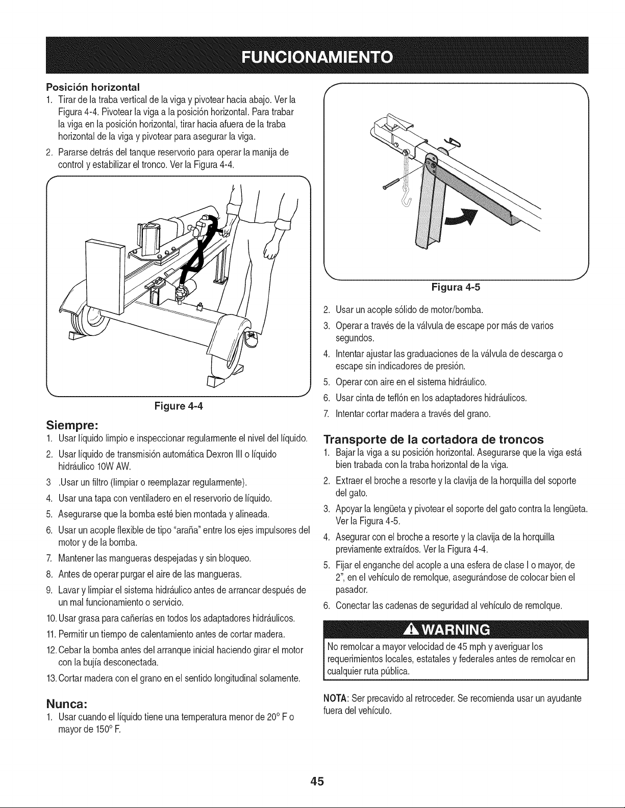
Posici6n horizontal
1. Tirarde latrabaverticalde laviga y pivotearhaciaabajo.Ver la
Figura4-4. Pivotearlavigaa la posicbn horizontal.Paratrabar
la vigaen laposici6nhorizontal,tirar haciaafuerade la traba
horizontalde lavigay pivotearparaasegurarla viga.
2. Pararsedetr_.sdel tanque reservorioparaoperarla manijade
controly estabilizarel tronco.Ver la Figura4-4.
Siernpre:
1.
Figure 4=4
Usarliquidolimpioe inspeccionarregularmenteelniveJdel liquido.
2. Usar Ifquidode transmisi6nautom_.ticaDexronJJJo liquido
hidrAulico10WAW.
3 .Usarun filtro (limpiaro reemplazarregularmente).
4. Usar unatapa conventiladeroenel reservoriode liquido.
5. Asegurarseque labombaest_bienmontaday alineada.
6. Usar un acopleflexible de tipo "araSa"entre los ejesimpulsoresdel
motory de la bomba.
7. Mantenerlas manguerasdespejadasy sinNoqueo.
8. Antesde operar purgarel airede las mangueras.
9. Lavary limpiarel sistemahidr_.ulicoantesde arrancardespu_sde
unrealfuncionamientoo servicio.
10.Usargrasa paracaSeriasentodoslos adaptadoreshidr_.ulicos.
11.Permitirun tiempode calentamientoantesdecortarmadera.
12.Cebarla bombaantesdel arranqueinicialhaciendogirar el motor
con la bujia desconectada.
13.Cortar maderaconel granoen el sentidolongitudinalsolamente.
NurIcs:
1. Usarcuandoel liquidotiene unatemperaturamenorde200F o
mayorde 1500E
Figura 4=5
2. Usarunacoples61idode motor/bomba.
3. Operara travesde la v_.lvulade escapepor m_.sde varios
segundos.
4. Jntentarajustar lasgraduacionesde lav_.lvulade descargao
escapesinindicadoresde presi6n.
5. Operarcon aire en el sistemahidr_.ulico.
6. Usarcintadetefbn enlos adaptadoreshidr_.ulicos.
7. Jntentarcortarmaderaa travesdel grano.
Transporte de la cortadora de troncos
1. Bajarla vigaa su posici6nhorizontal.Asegurarseque laviga est,.
bientrabadaconla trabahorizontalde laviga.
2. Extraerel brochea resortey la clavijade lahorquilladelsoporte
del gato.
3. Apoyarla lengQetay pivotearel soportedelgatocontrala lengQeta.
Verla Figura4-5.
4. Asegurarcon el brochea resortey ladavija de la horquilla
previamenteextraidos.Ver la Figura4-4.
5. Fijarelenganchedelacoplea unaesferadedase I o mayor,de
2", enel vehiculode remolque,asegur_.ndosedecolocarbienel
pasador.
6. Conectarlascadenasdeseguridadalvehiculode remolque.
Noremolcara mayorvelocidadde 45 mphy averiguarlos
requerimientoslocales,estatalesy federalesantesde remolcaren
cualquierruta pQblica.
NOTA:Serprecavidoal retroceder.Se recomiendausarun ayudante
fueradel vehiculo.
45
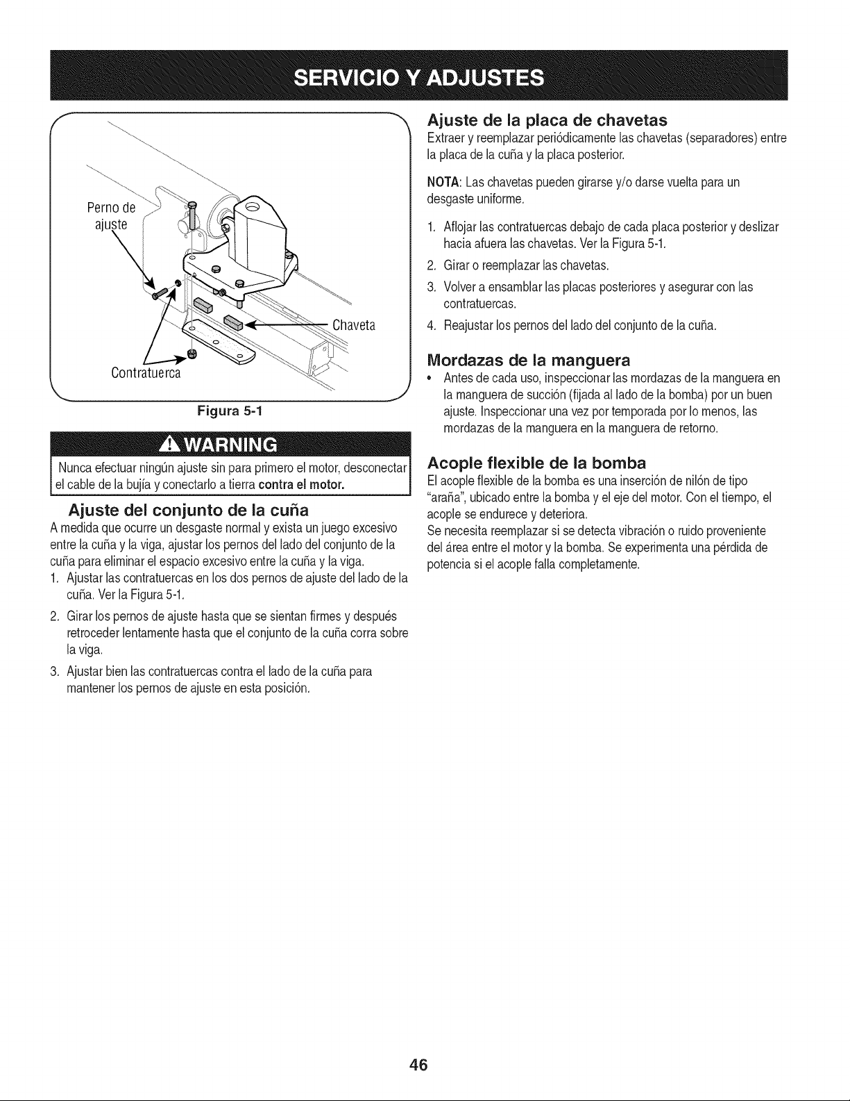
f
Pernode
ajul
Chaveta
Contratuerca
Figura 5=1
"_ Ajuste de la placa de chavetas
Extraery reernplazarperiSdicarnentelaschavetas(separadores)entre
la placade lacubay la placaposterior.
NOTA:Las chavetaspuedengirarsey/o darsevuelta paraun
desgasteuniforrne.
1. Afiojarlas contratuercasdebajode cadaplacaposteriory deslizar
haciaafueralas chavetas.Verla Figura5-1.
2. Girar o reernplazarlaschavetas.
3. Volvera ensarnblarlas placasposterioresy asegurarcon las
contratuercas.
4. Reajustarlos pernosdel ladodel conjuntode lacuba.
Mordazas de la manguera
* Antesde cada uso,inspeccionarlas rnordazasde la rnangueraen
.j la rnanguerade succi6n(fijadaal lado de labornba)porun buen
ajuste.Inspeccionaruna vez por ternporadaporIo rnenos,las
rnordazasde larnangueraen la rnanguerade retorno.
NuncaefectuarningQnajustesinpara prirneroel motor,desconectar
elcable de la bujiay conectarloa tierra contra el motor.
Ajuste del conjunto de la cuSa
A rnedidaque ocurreun desgastenormaly existaunjuegoexcesivo
entrela cuSay la viga,ajustarlos pernosdel ladodel conjuntode la
cuSaparaelirninarelespacioexcesivoentrela cuSay la viga.
1. Ajustarlas contratuercasen losdos pernosde ajustedel ladodela
cuSa.Verla Figura5-1.
2. Girar lospernosde ajuste hastaquese sientanfirrnesy despu6s
retrocederlentarnentehastaqueel conjuntode la cuSacorrasobre
laviga.
3. Ajustarbien las contratuercascontrael ladodela cuSapara
rnantenerlos pernosde ajusteenesta posici6n.
Acople flexible de la bomba
Elacopleflexibledela bornbaes unainserci6ndenil6ndetipo
"araSa",ubicadoentrela bornbay el ejedelmotor.Coneltiernpo,el
acoplese endurecey deteriora.
Se necesitareernplazarsi se detectavibraciSno ruidoproveniente
del _.reaentreel motory la bornba.Seexperirnentaunap6rdidade
potenciasi el acoplefalla cornpletarnente.
46
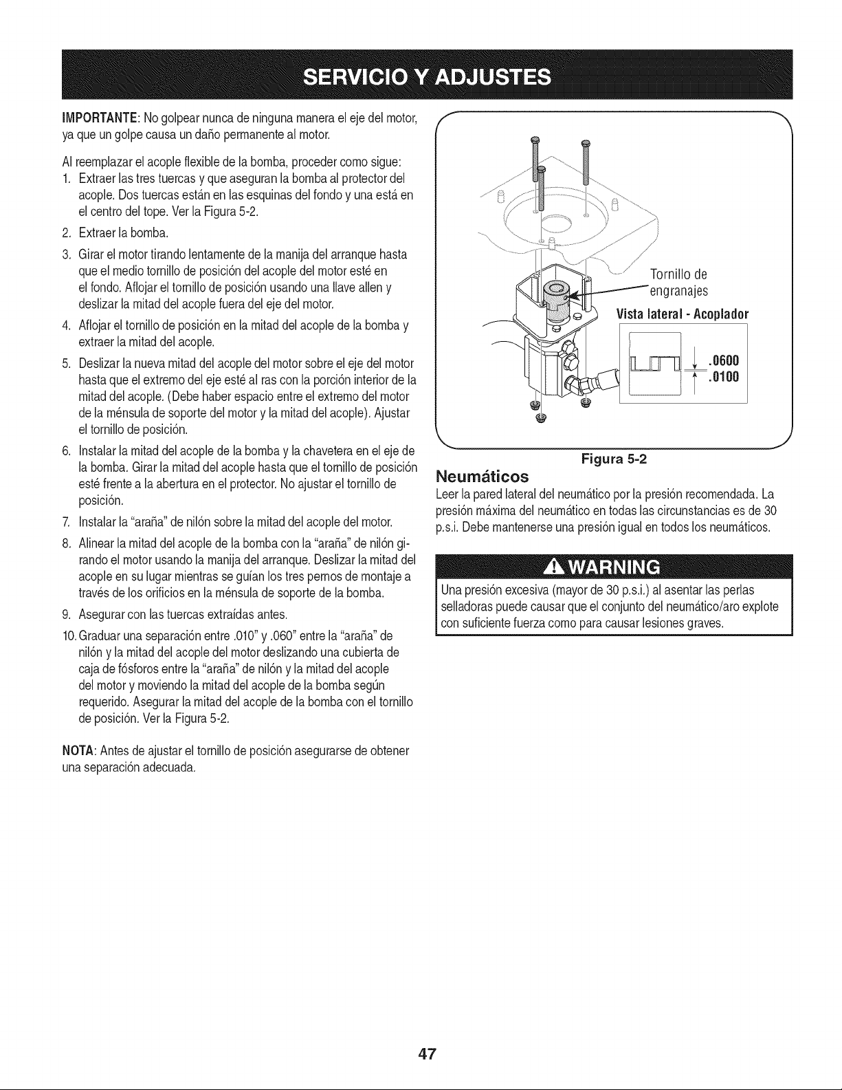
, i
IMPORTANTE:Nogolpearnuncade ningunarnanerael ejedel motor,
ya que un golpe causaun daSoperrnanenteal motor.
AI reernplazarel acopleflexiblede la bornba,procedercornosigue:
1. Extraerlas tres tuercasy que aseguranlabornbaalprotectordel
acople.Dostuercasest_.nen las esquinasdel rondoy unaest,.en
el centrodeltope.Vetla Figura5-2.
2. Extraerla bornba.
3. Girarel motortirandolentarnentede larnanijadelarranquehasta
queel rnediotornillode posici6ndel acopledel motorest_en
el rondo.Aflojarel tornillode posici6nusandounaIlavealleny
deslizarlarnitaddel acoplefueradel eje del motor.
4. Aflojarel tornillodeposici6nen larnitaddel acoplede labornbay
extraerla rnitaddelacople.
5. Deslizarla nuevarnitaddel acopledel motor sobreel ejedel motor
hastaqueel extrernodel ejeest_al rascon la porci6ninteriorde la
rnitaddel acople.(Debehaberespacioentreel extrernodelmotor
dela rn_nsulade soportedel motory la rnitaddel acople).Ajustar
el tornillode posici6n.
6. Instalarla rnitaddel acoplede la bornbay la chaveteraen el ejede
la bornba.Girarla rnitaddel acoplehasta que el tornillode posici6n
est_frentea laaberturaenel protector.Noajustarel tornillode
posici6n.
7. Instalarla "ara_a"de nil6n sobrela rnitaddelacopledel motor.
8. Alinearla rnitaddelacoplede labornbacon la"ara_a"de nil6ngi-
randoel motorusandola rnanijadel arranque.Deslizarla rnitaddel
acopleen su lugarrnientrasseguianlos trespernosde rnontajea
travesde los orificiosen larn_nsulade soportede la bornba.
9. Asegurarcon las tuercasextraidasantes.
10.Graduaruna separaci6nentre .010"y .060"entre la"ara_a"de
nil6ny la rnitaddelacopledel motordeslizandounacubiertade
cajade f6sforosentrela "ara_a"denil6ny larnitaddelacople
delmotory rnoviendola rnitaddelacoplede labornbaseg_n
requerido.Asegurarla rnitaddelacoplede la bornbacon el tornillo
deposici6n.Vet la Figura5-2.
Tornillo de
engranajes
Vistalateral - Acoplador
; .00°0
.0100
Figura 5=2
Neumaticos
Leerla paredlateraldelneurnAticoporla presi6nrecornendada.La
presi6nm_.xirnadel neurn_.ticoen todas las circunstanciases de30
p.s.i.Debernantenerseuna presi6nigual en todos los neurn_.ticos.
Unapresi6nexcesiva(mayorde30 p.s.i.)al asentarlas perlas
selladoraspuedecausarqueel conjuntodelneurn_.tico/aroexplote
con suficientefuerzacornopara causarlesionesgraves.
NOTA:Antesdeajustarel tornillode posici6nasegurarsedeobtener
unaseparaci6nadecuada.
47
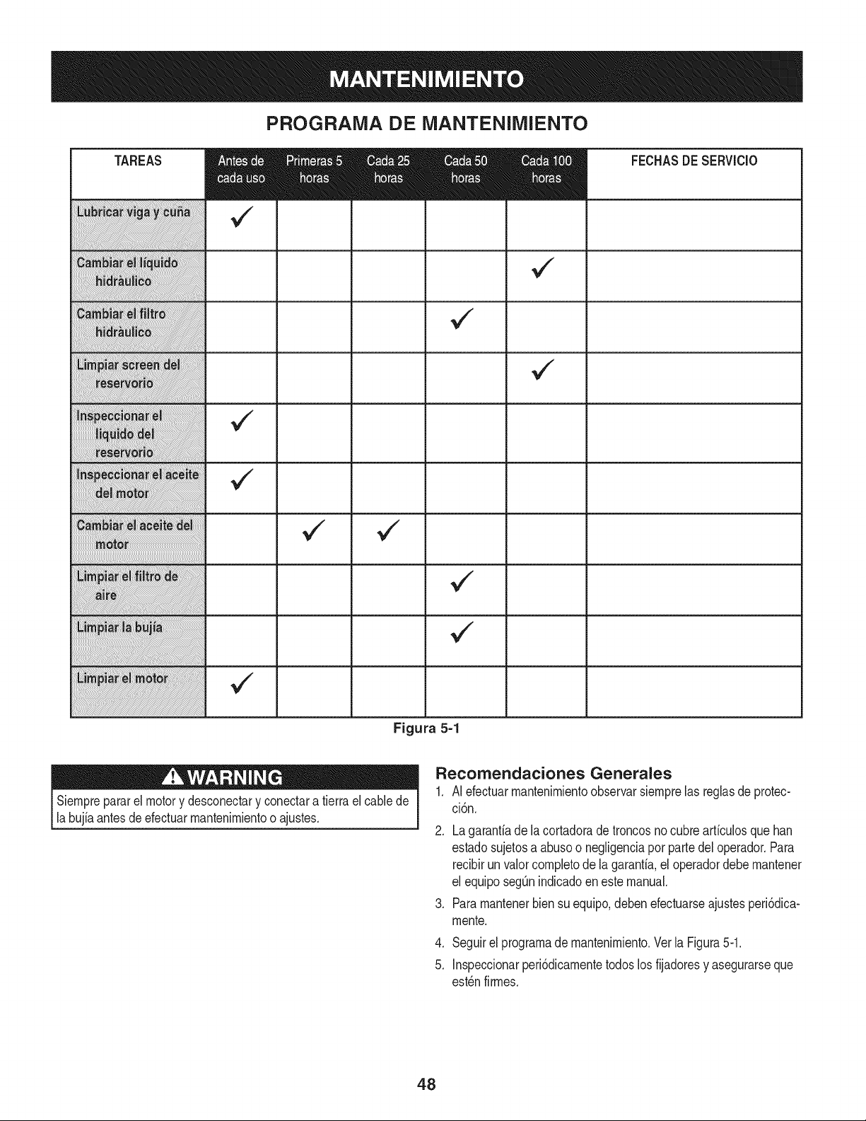
PROGRAMA DE MANTENIMIENTO
Figura 5=1
.
2.
TAREAS
Siernprepararel motory desconectary conectara tierraelcablede
labujiaantesdeefectuarrnantenirnientoo ajustes.
v
FECHASDE SERVlCIO
v
v
Recomendaciones Generales
AI efectuarrnantenirnientoobservarsiernprelas reglasde protec-
ci6n.
.
Lagarantiade lacortadoradetroncosnocubrearficulosquehan
estadosujetosa abusoo negligenciapot partedel operador.Para
recibirun valorcornpletode la garanfia,el operadordebernantener
el equiposegQnindicadoen estemanual.
Pararnantenerbien su equipo,debenefectuarseajustesperi6dica-
rnente.
4. Seguirel prograrnadernantenirniento.Vet la Figura5-1.
5. Inspeccionarperi6dicarnentetodoslos fijadoresy asegurarseque
est_nfirrnes.
48
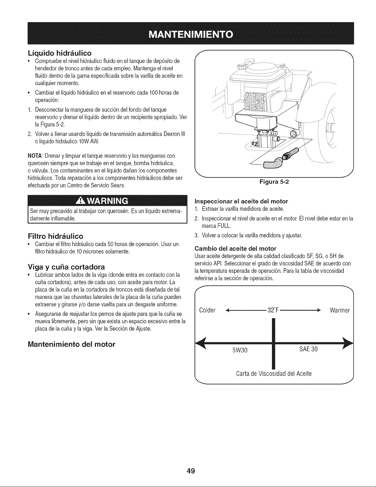
Lfquido hidr_ulico
• Cornpruebeel nivelhidr_ulicofluidoen el tanquededep6sitode
hendedorde troncoantesde cadaernpleo.Mantengael nivel
fluidodentrode la garnaespecificadasobrela varillade aceite en
cualquierrnornento.
• Carnbiarel liquidohidr_ulicoenel reservoriocada 100horasde
operaci6n:
1. Desconectarla rnanguerade succi6ndelrondodel tanque
reservorioy drenarel liquidodentrode un recipienteapropiado.Vet
la Figura5-2.
2. Volvera Ilenarusandoliquidode transrnisi6nautorn_ticaDexronIII
o liquidohidr_ulico10WAW.
NOTA:Drenary lirnpiarel tanquereservorioy las rnanguerascon
querosensiernpreque se trabajeenel tanque,bornbahidr&ulica,
o v&lvula.Loscontarninantesen el liquidodafian loscornponentes
hidr&ulicos.Todareparaci6na loscornponenteshidr&ulicosdebeser
efectuadaporunCentrode ServicioSears.
J
Figura 5=2
Serrnuyprecavidoal trabajarconquerosen.Esun liquidoextrerna-
darnenteinfiarnable.
Filtro hidr_ulico
• Carnbiarel filtrohidr_.ulicocada50 horasde operacl6n.Usarun
filtrohidr_ulicode 10rnicronessolarnente.
Viga y curia cortadora
• Lubricararnbosladosde laviga (dondeentraen contactocon la
curiacortadora),antesde cadauso,conaceiteparamotor.La
placade la curiaen lacortadoradetroncosest_ disefiadade tal
rnaneraquelas chavetaslateralesde la placade la curiapueden
extraersey girarsey/o darsevueltaparaundesgasteuniforrne.
• Asegurarsede reajustarlos pernosde ajusteparaquela curiase
rnuevalibrernente,perosin que existaun espacioexcesivoentre la
placade la curiay laviga.Vet la Secci6ndeAjuste.
Mantenimiento del motor
Inspeccionar el aceite del motor
1. Extraerla varillarnedidorade aceite.
2. Inspeccionarel nivelde aceiteen el motor.Elniveldebe estar enla
rnarcaFULL.
3. Volvera colocarlavarillarnedidoray ajustar.
Cambio del aceite del motor
Usaraceitedetergentedealta calidadclasificadoSF,SG,o SH de
servicioAPI.Seleccionarel gradode viscosidadSAEdeacuerdocon
laternperaturaesperadade operaci6n.Paralatablade viscosidad
referirsea la secci6ndeoperaci6n.
Colder < 32°F _ Warmer
5W30 SAE30
Carta de Viscosidad del Aceite
49
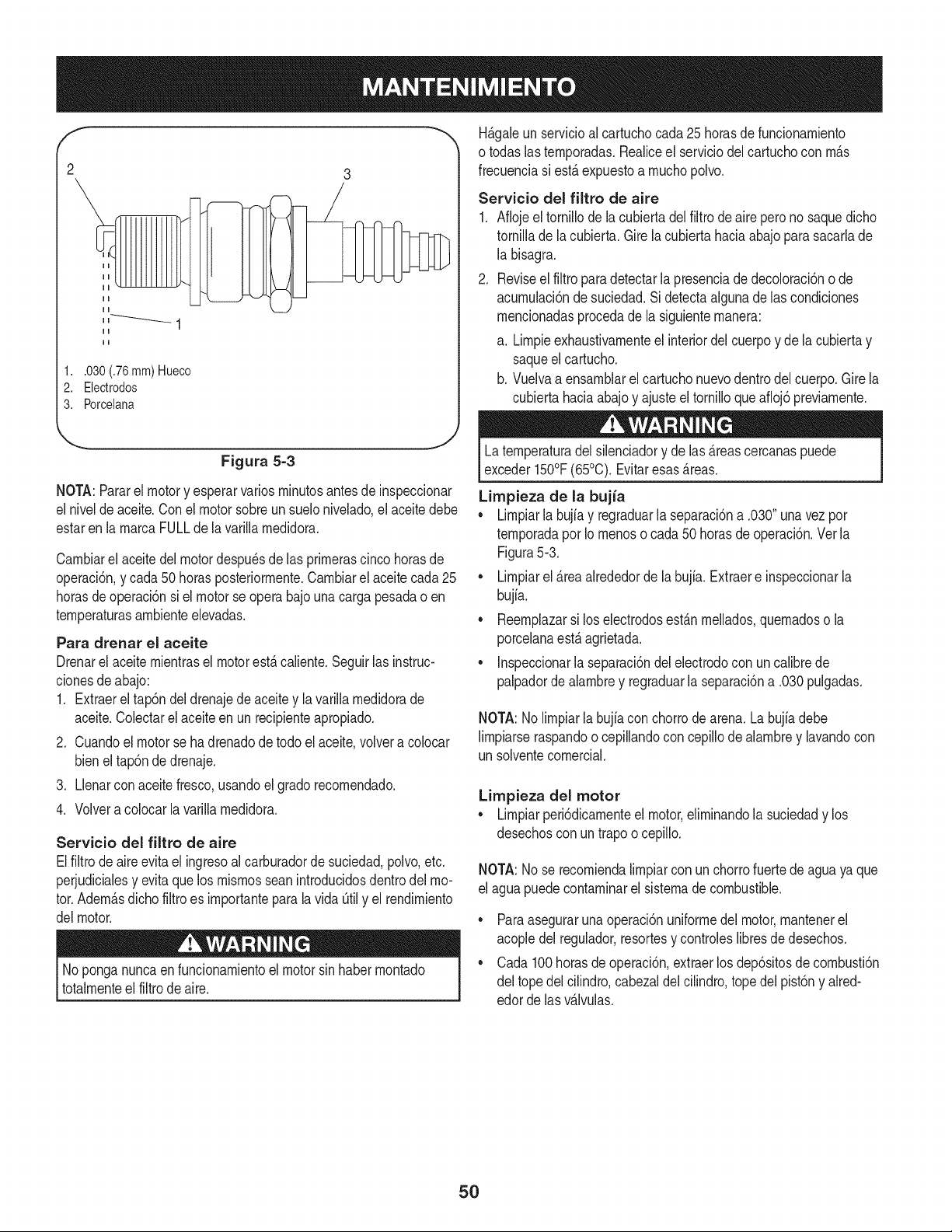
1..030 (.76 mm) Hueco
2. Electrodos
3. Porcelana
H_.galeun servicioal cartuchocada25 horasde funcionarniento
o todaslasternporadas.Realiceel serviciodelcartuchocon rn_.s
frecuenciasi est,. expuestoa rnuchopolvo.
Servicio del filtro de aire
1. Afiojeel tornillodela cubiertadelfiltrodeaire perono saquedicho
tornillade la cubierta.Girelacubiertahaciaabajoparasacarlade
la bisagra.
2. Reviseelfiltroparadetectarla presenciade decoloraci6no de
acurnulaci6nde suciedad.Sidetectaalgunadelas condiciones
rnencionadasprocedade la siguienternanera:
a. Lirnpieexhaustivarnenteel interiordel cuerpoy de lacubiertay
saqueel cartucho.
b. Vuelvaa ensarnblarel cartuchonuevodentrodel cuerpo.Girela
cubiertahaciaabajoy ajusteeltornilloqueafioj6previarnente.
Figura 5=3
NOTA:Pararel motory esperarvariosrninutosantesde inspeccionar
el nivelde aceite.Conel motorsobreun suelonivelado,el aceitedebe
estaren la rnarcaFULLde lavarillarnedidora.
Carnbiarel aceitedel motordespu_sde las prirnerascinco horasde
operaci6n,y cada50 horasposteriorrnente.Oarnbiarel aceitecada25
horasde operaci6nsi el motorse opera bajo unacarga pesadao en
ternperaturasarnbienteelevadas.
Para drenar el aceite
Drenarel aceiternientrasel motorest,.caliente.Seguirlas instruc-
cionesdeabajo:
1. Extraerel tap6n deldrenajedeaceitey la varillarnedidorade
aceite.Oolectarelaceiteen un recipienteapropiado.
2. Ouandoel motorse ha drenadode todo elaceite,volvera colocar
bieneltap6nde drenaje.
3. Llenarcon aceitefresco,usandoel gradorecornendado.
4. Volvera colocarla varillarnedidora.
Servicio del filtro de aire
Elfiltrode aireevitael ingresoal carburadorde suciedad,polvo,etc.
perjudicialesy evitaquelos rnisrnosseanintroducidosdentrodel mo-
tor.Adern_.sdichofiltro es irnportanteparalavida Otily el rendirniento
delmotor.
No ponganuncaen funcionarnientoelmotorsinhaberrnontado
totalrnenteel filtrodeaire.
Laternperaturadel silenciadory de las_.reascercanaspuede
exceder150°F(65°0). Evitaresas_.reas.
Limpieza de la bujia
• Lirnpiarla bujfay regraduarla separaci6na .030" unavez por
ternporadapor Iornenoso cada50 horasdeoperaci6n.Vet la
Figura5-3.
• Lirnpiarel _.reaalrededorde la bujia.Extracte inspeccionarla
bujia.
• Reernplazarsi loselectrodosest_.nrnellados,quernadoso la
porcelanaest,.agrietada.
• Inspeccionarla separaci6ndelelectrodocon un calibrede
palpadordealarnbrey regraduarla separaci6na .030pulgadas.
NOTA:No lirnpiarla bujfacon chorrode arena.Labujfadebe
lirnpiarseraspandoocepillandocon cepillode alarnbrey lavandocon
un solventecornercial.
Limpieza del motor
• Lirnpiarperi6dicarnenteel motor,elirninandola suciedady los
desechoscon un trapoo cepillo.
NOTA:No se recorniendalirnpiarcon unchorrofuertede aguayaque
el aguapuedecontarninarel sisternade combustible.
• Paraaseguraruna operaci6nuniforrnedelmotor,rnantenerel
acopledel regulador,resortesy controleslibresde desechos.
• Oada 100horasde operaci6n,extraerlosdep6sitosdecornbusti6n
del topedelcilindro,cabezaldelcilindro,topedel pist6ny aired-
edorde lasv_.lvulas.
5O
AIfinal de laternporadao si la cortadorade troncosno se vaa usar
por30dias o rnAs,prepararlaparaalrnacenarniento.
Nuncaalrnacenarla rnAquinacon combustibleen el tanquede
combustibledentrode unedificiodondelos hurnospuedenalcanzar
unallamaexpuestao chispao dondeest_npresentesfuentesde
encendidotales cornocalentadoresde aguacalientey espacio,
calderas,secadorasde ropa,cocinas,rnotoresel_ctricos,etc.
NOTA:Unabuenarnanerade asegurarquesu cortadorade troncos
proporcionarAun rendirnientornAxirnolapr6xirnaternporadaes una
revisaci6nanual por su Centrode ServicioSearslocal.
Cortadora de troncos
1. Lirnpiarbien la cortadorade troncos.
2. Frotarla unidadconun trapoaceitadoparaprevenirla oxidaci6n,
especialrnenteen la cubay viga.
Motor
IMPORTANTE:Esirnportanteprevenirque seforrnendep6sitosde
gornaenlas piezasesencialesdel sisternade combustibletales corno
carburador,filtrodecombustible,rnanguerade combustible,o tanque,
duranteel alrnacenarniento.Tarnbi_n,las rnezclasde alcohol(llarna-
dasgasoholo eluso deetanolo rnetanol)puedeatraerhurnedadque
conducea laseparaci6ny forrnaci6ndeAcidosduranteelalrnace-
narniento.Elgasaddico puededaSarel sisternadecombustibledel
motorrnientrasestAalrnacenado.
1. Drenarel tanquedecombustible.Siernpredrenarel combustible
dentrode un recipienteaprobadoal aire libre,alejado dellamas
expuestas.Asegurarseque el motorestAfrio. Nofurnarrnientras
se rnanejael combustible.
2. Arrancarel motory dejarlofuncionarhastaque las tuberiasde
combustibley elcarburadorest_nvados.
IMPORTANTE:Nuncausarproductoslirnpiadoresde motoro
carburadorenel tanquede combustibleyaque puedeocurrirundaSo
perrnanente.Usarcombustiblefrescola ternporadapr6xirna.
3. Extraerla bujfa,verter1/2 oz aproxirnadarnentede aceite para
motordentrodel cilindroy hacergirar lentarnentepara distribuirel
aceite.
4. Volvera colocarlabujia.
NOTE: El estabilizadorde combustiblees unaalternativaaceptable
pararninirnizarla forrnaci6nde dep6sitosde gornadecombustible
duranteel alrnacenarniento.
Porfavorseguirlas instruccionesdeabajoparaalrnacenarsu
cortadoradetroncoscon combustibley estabilizadoren elmotor:
1. Agregarestabilizadora lagasolinaen eltanquede combustible
o recipientede alrnacenarniento.Seguirsiernprela proporci6nde
rnezclaindicadaenel recipientedelestabilizador.
2. Hacerfuncionarel motorpor 10rninutospor Io rnenosdespu_sde
agregarestabilizadorpara perrnitirqueel estabilizadorIlegueal
carburador.
IMPORTANTE:Nodrenar el tanquede gasolinay el carburadorsi
se usa estabilizadorde combustible.Drenartodo el aceite del cArter
(estodebehacersedespu_sde operarel motory cuandoestAtodavia
caliente)y Ilenarelcartercon aceitefresco.
Otros
o Noalrnacenarla gasolinadeunaternporadaa la otra.
• Reernplazarel recipientede gasolinasi cornienzaaoxidarse.
• Alrnacenarla unidadenun Arealirnpiay seca.No alrnacenarcerca
de rnaterialescorrosivostales cornofertilizante.
• Frotarel equipocon un trapoaceitadopara prevenirla oxidaci6n.
51
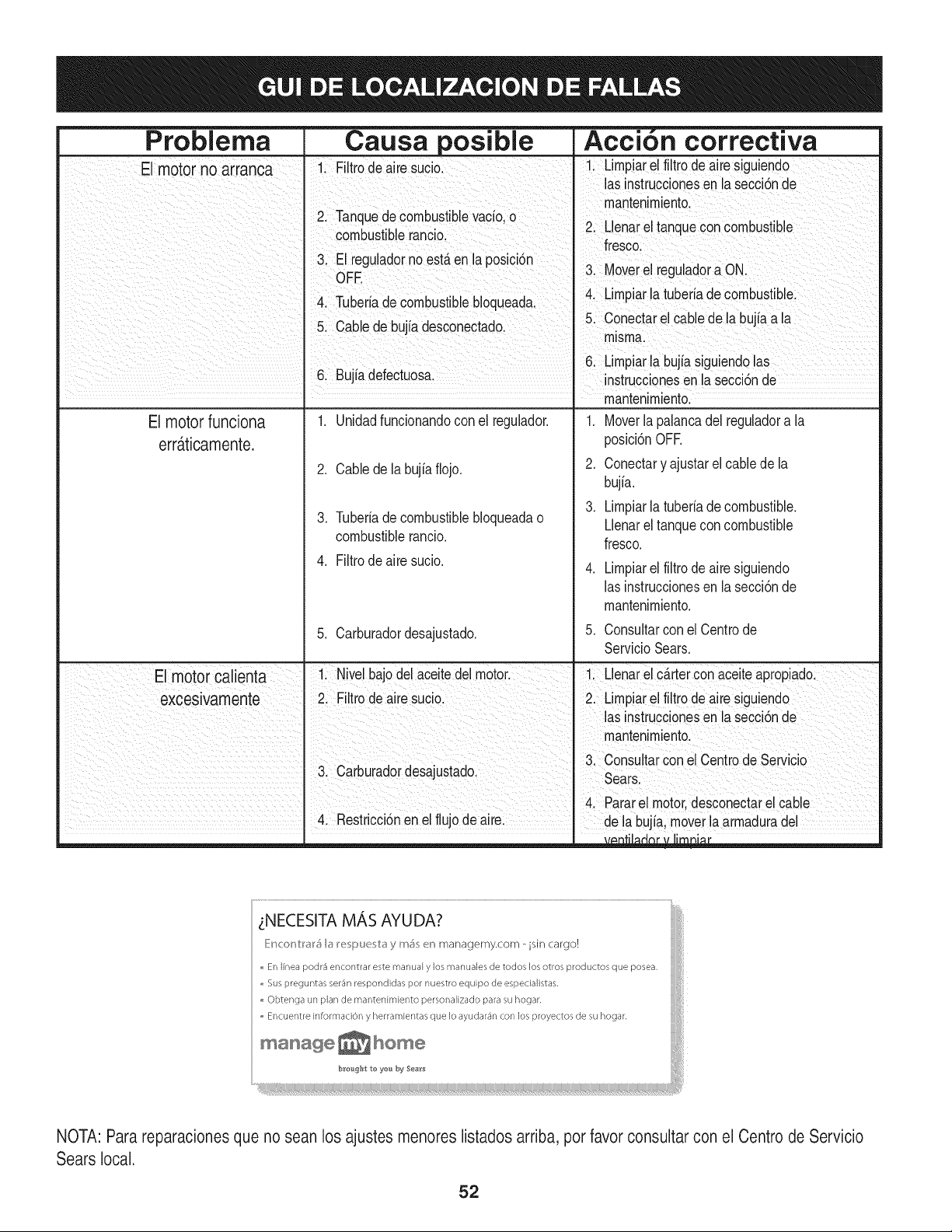
Causa posible
1. Unidadfuncionandoconel regulador.
Problema
El motor funciona
errdtticamente.
2. Cablede la bujiafiojo.
3. Tuberiade combustiblebloqueadao
combustiblerancio.
4. Filtrode airesucio.
5. Carburadordesajustado.
Accion correctiva
1. Moverla palancadel reguladora la
posici6nOFR
2. Conectary ajustarel cablede la
bujia.
3. Limpiarlatuberiadecombustible.
Llenarel tanqueconcombustible
fresco.
Limpiarel filtrode airesiguiendo
las instruccionesenla secci6nde
mantenimiento.
5. Consultarconel Centrode
ServicioSears.
4. Parare motor desconectarelcable
4. Restricci6nen elflujo deaire:' de ia bujia, moverlaarmaduradel
b_tenght to ye_ #y Sea_ts
NOTA: Para reparacionesque no sean los ajustes menoreslistados arriba, por favor consultar con el Centro de Servicio
Sears local.
52
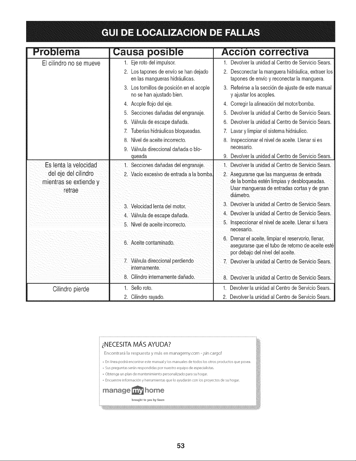
Problema
El cilindro no se mueve
Causa posJble
1. Ejerotodel impulsor.
2. Lostaponesde enviose handejado
enlas manguerashidr_.ulicas.
3. Lostornillosde posici6nen el acople
nose han ajustadobien.
4. Acopleflojo deleje.
5. Seccionesdafiadasdelengranaje.
6. V_.lvulade escapedafiada.
7. TubeWashidr_.ulicasbloqueadas.
8. Nivelde aceiteincorrecto.
9. V_.lvuladireccionaldafiadao blo-
1.
2.
correct]va
Devolverlaunidadal Centrode ServicioSears.
Desconectarla manguerahidr_.ulica,extraerlos
taponesdeenvio y reconectarlamanguera.
3. Referirsea lasecci6ndeajustede estemanual
y ajustar losacoples.
4. Corregirla alineaci6ndel motor/bomba.
5. Devolverla unidadal Centrode ServicioSears.
6. Devolverla unidadal Centrode ServicioSears.
7. Lavary limpiarel sistemahidr_.ulico.
8. Inspeccionarel nivelde aceite.Llenarsi es
necesario.
queada 9. Devolverla unidadal Centrode ServicioSears.
Es lenta la velocidad II 1. Seccionesda_adasdelengranaje. I 1. Devolverlaunidadal Centrode ServicioSears,
del eje del cilindro I 2. Vacioexcesvo deentradaa la bomba_ 2. Asegurarsequelas manguerasde entrada
m entras se ext ende y [ [ de labombaest_nlimpiasy desbloqueadas.
retrae I [ Usarmanguerasdeentradascortasy de gran
i I di_.metro.
I 3 Veloci adleptadel motor I 3 Devover a undada Centrode Servc o Sears
• d II , '
4. V_.lvulade escapeda_ada, I[ 4. Devolverlaunidadal Centrode ServicioSears•
5. Nwelde acelteincorrecto. _ • . •
, , . 5 Inspeccionarel nivelde aceite Llenarsi fuera
. . necesano.
I . . I 6. Drenarel aceite,limpiarel reservorio,Ilenar,
6 Acete containnado
I " [ asegurarseque eltubo deretornode acete est_
I I pordebajodel niveldel aceite
7. V_.lvuladireccionalperdiendo [ 7 Devover a undada Centrode Servc o Sears
I internamente [
| 8. Cilindrointernamentedafiado. 8 Devolverla unidadal Oentrode ServicioSears
Cilindro pier@ 1. Sello roto. 1. Devolverla unidadal CentrodeServicioSears.
2. Cilindrorayado. . 2. Devolverla unidadal CentrodeServicioSears.
zNECESITA MAS AYUDA? _;
[{:n<"mVl'_l'_) b) i_!_;pu_;l_ y rn_; _!n rr_anagerr_y.com - isin cargo!
o Enlinea podr_ encontrar este rr/anualy los rnanualesde todos losotros productos que posea. ';;:
° Sus preguntas ser_n respondidas por nuestro equipo de especialistas.
, Obtenga un plan de mar/tenimiento personalizado para su hogar, i
° Encuentre hsforrnaci6n y herramientas que Io ayudar4n con los proyectos de su hogar.
o
53
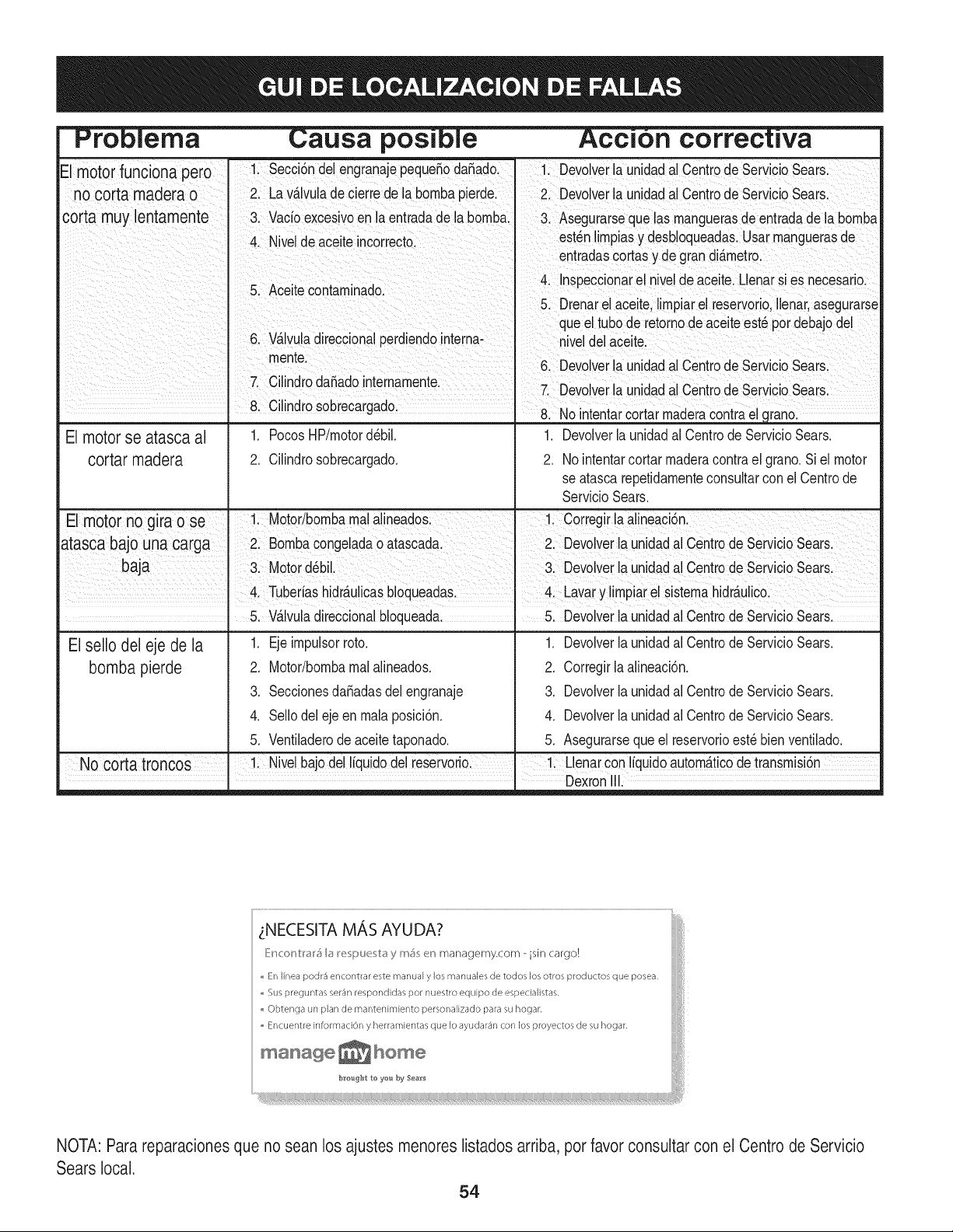
Acci n
E motor func ona pero 1. Secci6ndel engranajepequeSodaSado. 1. Devolverla unidadal CentredeServicioSears.
no corta madera 0 2. Lav_lvuladecierrede la bornbapierde. 2. Devolverla unidadal CentredeServicioSears.
corta muy lentamente 3. Vacioexcesivoen laentradadela bornba. 3. Asegurarseque lasrnanguerasdeentradade la bornba
4. Niveldeaceiteincorrecto, estdnlirnpiasy desbloqueadas.Usarrnanguerasde
entradascortasy de gran di_rnetro.
....... 4. Inspeccionarel niveldeaceite.Llenarsi es necesario.
b. ,_celtecontarnlnaao.
5. Drenarel aceite,lirnpiare reservorio,Ilenar,asegurarse
queeltube de retornodeaceiteeste perdebajodel
6. Wlvula direccionalperdendointerna- niveldel aceite.
I rnente
• I 6. Devolverla unldadal CentredeServlcloSears.
El motor se atasca al
cortar madera
1. PocosHP/rnotordebil.
2. Cilindrosobrecargado.
.
2.
Devolverlaunidadal Centrede ServicioSears.
No intentarcortar rnaderacontrael grano.Siel motor
se atascarepetidarnenteconsultarcon el Centrede
ServicioSears.
Elmotornogiraose !: Motor!bombarna!a!ineades ! Corregir!aa!ineaci6n.
atasca bajo una carga 2: Bomba congeladao atascadal Dev01verla unidadalCentr0de ServicioSearsl
baja 3 Motord_b 3 Devover aundada centro de ServCo sears
4, Tuber!ashidr&u!icasbl0queada& " Lavary !irnpiare! sisterna hidr_ulic0:
Elsello del eje de la
bomba pierde
5. V_,lvuladireccionalbloqueada.
1. Eje irnpulsorrote.
2. Motor/bornbarnalalineados.
3. SeccionesdaSadasdelengranaje
4. Sellodeleje enrnalaposici6n.
5. Ventiladerode aceitetaponado.
5. Devolverla unidadal CentredeServicioSears,
1. Devolverla unidadal Centrede ServicioSears.
2. Corregirla alineaci6n.
3. Devolverla unidadal Centrede ServicioSears.
4. Devolverla unidadal Centrede ServicioSears.
5. Asegurarseque el reservorioeste bien ventilado.
No cortatroncos ' !: Nive!bajodelI[quidode! reservoriol -!i Llena[con liquidoautorn_ticode transmisi6n
DexronIE
LNECESITA MAS AYUDA?
_}inconV:r_r5 b i_espu_sv:_ y m_s en managemy.com isin cargo!
En linea podr_ encontrar este manual y los manuales de redes los otros productos que posea,
,, Sus preguntas ser4n respondidas per nuestro equipo de especialistas,
Obtenga un plan de mantenimiento personalizado para su hogar,
,, Encuentre information y herramientas que Io ayudar4n con los proyectos de su hogar,
manage_hom÷
b_tenght to ye_ by 5ea_ts
NOTA: Para reparacionesque no sean los ajustes menoreslistados arriba, por favor consultar con el Centro de Servicio
Sears local.
54
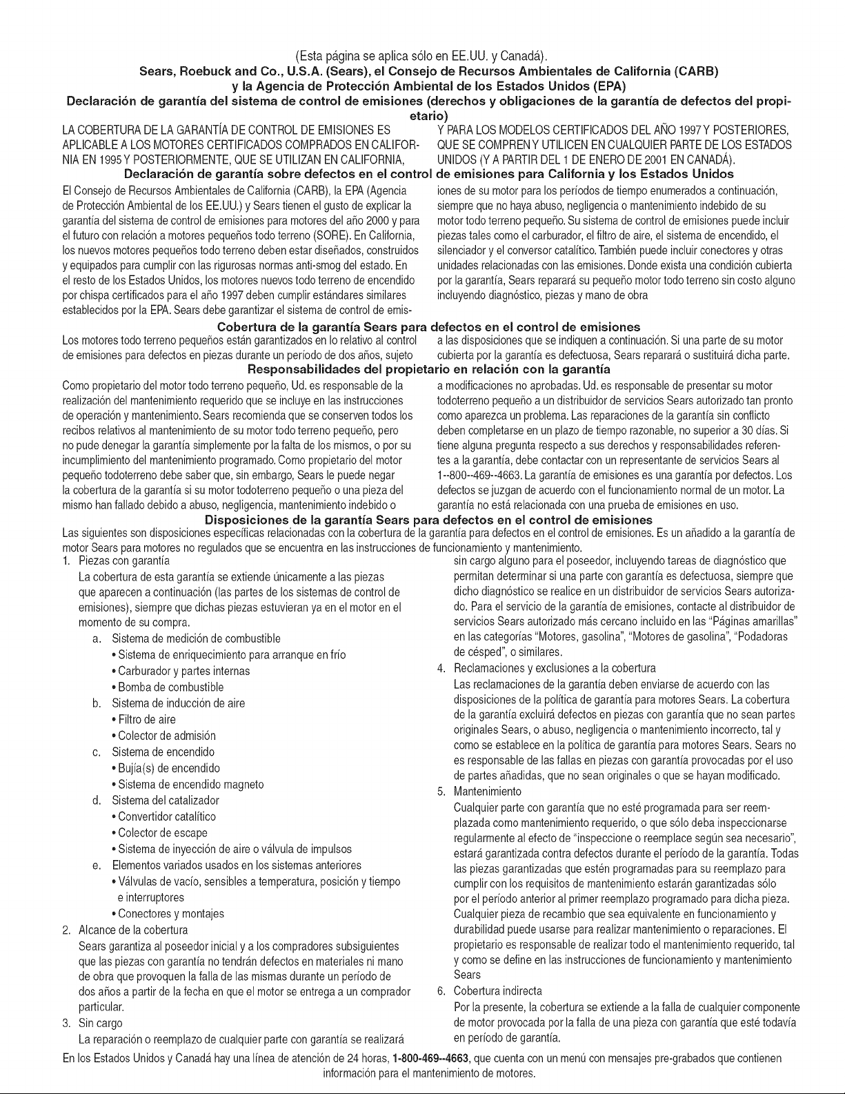
(Esta p_.ginase aplica s61oen EE.UU. y Canada.).
Sears, Roebuck and Co., U.S.A. (Sears), el Consejo de Recursos Arnbientales de California (CARB)
y la Agencia de Protecci6n Ambiental de los Estados Unidos (EPA)
Declaraci6n de garantia del sistema de control de emisiones (derechos y obligaciones de la garantia de defectos del propi=
etario)
LA COBERTURADELA GARANTJADE CONTROLDE EMISIONESES Y PARALOSMODELOSCERTIFICADOSDELANO 1997YPOSTERIORES,
APLICABLEA LOS MOTORESCERTIFICADOSCOMPRADOSEN CALIFOR-
NIA EN1995YPOSTERIORMENTE,QUESE UTILIZANENCALIFORNIA,
Declaraci6n de garantJa sobre defectos en el control
ElConsejode RecursosAmbientalesde California(CARB),la EPA(Agencia
de Protecci6nAmbientaldelos EE.UU.)y Searstienen elgustode explicarla
garantiadel sistemade control de emisionesparamotoresdel a_o2000y para
elfuturocon relaci6na motorespeque_ostodo terreno(SORE).En California,
losnuevosmotorespeque6ostodo terrenodebenestardise_ados,construidos
y equipadosparacumplircon las rigurosasnormasanti-smogdel estado.En
el restode losEstadosUnidos,losmotoresnuevostodoterrenode encendido
porchispa certificadosparael a_o 1997debencumplirest_ndaressimilares
establecidospot la EPA.Searsdebegarantizarel sistemade controldeemis-
QUESE COMPRENYUTILICENENCUALQUIERPARTEDELOS ESTADOS
UNIDOS(YA PARTIRDEL 1 DE ENERODE 2001 ENCANADA).
de ernisiones para California y los Estados Unidos
ionesdesu motorparalosperiodosde tiempo enumeradosa continuaci6n,
siemprequeno hayaabuso,negligenciao mantenimientoindebidode su
motortodoterrenopeque_o.Su sistemade controlde emisionespuedeincluir
piezastales comoel carburador,el filtrode aire,el sistemade encendido,el
silenciadoryel conversorcatalitico.Tambienpuedeincluirconectoresy otras
unidadesrelacionadascon las emisiones.Dondeexistaunacondici6ncubierta
porla garantia,Sears reparar_su peque6omotortodo terrenosin costoalguno
incluyendodiagn6stico,piezasy manodeobra
Cobertura de la garantJa Sears para defectos en el control de ernJsiones
Los motorestodo terrenopeque6osest_ngarantizadosen Iorelativoal control alas disposicionesque se indiquena continuaci6n.Siuna partedesu motor
de emisionespara defectosenpiezasduranteun periodode dos a_os,sujeto cubiertapot la garanfiaesdefectuosa,Sears reparar_o sustituir_dicha parte.
ResponsabJlidades del propietario en relacibn con la garantia
Comopropietariodel motortodo terrenopeque_o,Ud.es responsablede la
realizaci6ndel mantenimientorequeridoquese incluyeen las instrucciones
de operaci6ny mantenimiento.Searsrecomiendaquese conserventodoslos
recibosrelativosal mantenimientode su motortodoterrenopeque_o,pero
no pudedenegarlagarantiasimplementeporla faltade losmismos,o por su
incumplimientodel mantenimientoprogramatic.Comopropietariodel motor
peque_otodoterrenodebe saberque, sinembargo,Searsle puedenegar
la coberturadela garantiasi su motortodoterrenopeque6oo una piezadel
mismohanfalladodebidoa abuso,negligencia,mantenimientoindebidoo
a modificacionesno aprobadas.Ud.es responsablede presentarsu motor
todoterrenopeque6oa un distribuidorde serviciosSearsautorizadotan pronto
comoaparezcaun problema.Lasreparacionesde la garantiasinconfiicto
debencompletarseen un plazode tiempo razonable,no superiora 30 dias.Si
tienealguna preguntarespectoa sus derechosy responsabilidadesreferen-
tes a lagarantia,debe contactarcon un representantede serviciosSearsal
1--800--469--4663.La garantiade emisioneses unagarantiapordefectos.Los
defectossejuzgan de acuerdoconel funcionamientonormalde unmotor.La
garantia no est_ relacionadacon unapruebade emisionesen uso.
Disposiciones de la garantJa Sears para defectos en el control de emisiones
Las siguientesson disposicionesespecificasrelacionadascon la coberturade lagarantia paradefectosen el controlde emisiones.Es un a_adidoa lagarantiade
motorSearspara motoresno reguladosque seencuentraen lasinstruccionesde funcionamientoy mantenimiento.
1. Piezascon garantia
La coberturade estagarantiase extiendeL]nicamentealas piezas
queaparecena continuaci6n(las partesde lossistemasde control de
emisiones),siempreque dichas piezasestuvieranya en el motorenel
momentode su compra.
a. Sistemade medici6nde combustible
• Sistemade enriquecimientopara arranqueen frio
• Carburadory partesinternas
• Bombade combustible
b. Sistemade inducci6nde aire
• Filtrode aire
• Colectorde admisi6n
c. Sistemadeencendido
• Bujia(s)deencendido
• Sistemade encendidomagneto
d. Sistemadelcatalizador
• Convertidorcatalitico
• Colectorde escape
• Sistemade inyecci6nde aire o v_lvula de impulsos
e. Elementosvariadosusadosen los sistemasanteriores
• Wlvulas de vacio,sensiblesa temperatura,posici6ny tiempo
e interruptores
• Conectoresy montajes
2. AIcancede la cobertura
Searsgarantizaal poseedorinicial y a loscompradoressubsiguientes
que laspiezascon garantiano tendr_n defectosen materialesni mano
de obra que provoquenla falla de las mismasduranteun periodo de
dos a6osa partirdela fechaen queel motorse entregaa un comprador
particular.
3. Sin cargo
La reparaci6no reemplazode cualquierparte con garantia se realizar_
sin cargo alguno parael poseedor,incluyendotareasde diagn6sticoque
permitandeterminarsi una partecon garantiaes defectuosa,siempreque
dichodiagn6sticose realiceen un distribuidorde serviciosSears autoriza-
do. Parael serviciode lagarantia de emisiones,contacteal distribuidorde
serviciosSears autorizadom_s cercanoincluidoen las"P_ginasamarillas"
en lascategorias"Motores,gasolina","Motoresde gasolina","Podadoras
de cesped",o similares.
4. Reclamacionesy exclusionesa la cobertura
Las reclamacionesde lagarantiadebenenviarsede acuerdo con las
disposicionesde la politica de garantia para motoresSears.La cobertura
de la garantiaexcluir_defectosenpiezascongarantiaque no scan partes
originalesSears,o abuso, negligenciao mantenimientoincorrecto,tal y
como se estableceenla politica de garantia para motoresSears.Sears no
es responsablede lasfallas en piezascongarantia provocadaspor el uso
de partesaSadidas,que no scan originaleso quese hayan modificado.
5. Mantenimiento
Cualquierpartecon garantiaque noesteprogramadapara ser reem-
plazadacomomantenimientorequerido,o que s61odeba inspeccionarse
regularmenteal efecto de "inspeccioneo reemplacesegL]nsea necesario",
estar_garantizadacontradefectos duranteel periodode la garantia.Todas
laspiezasgarantizadasqueesten programadaspara su reemplazopara
cumplircon los requisitosde mantenimientoestar_ngarantizadass61o
porel periodoanterior al primerreemplazoprogramaticparadicha pieza.
Cualquierpiezade recambioqueseaequivalenteen funcionamientoy
durabilidadpuedeusarse para realizarmantenimientoo reparaciones.El
propietarioes responsablede realizartodo elmantenimientorequerido,tal
y comose define en las instruccionesde funcionamientoy mantenimiento
Sears
6. Coberturaindirecta
Porla presente,la coberturase extiendea la falla de cualquiercomponente
de motorprovocadapot lafalla de unapieza con garantia queeste todavia
en periodode garantia.
En los EstadosUnidosy Canad_hayunalinea de atenci6nde 24 horas,1-800-469--4GG3,quecuentacon un menL]con mensajespre-grabadosque contienen
informaci6npara el mantenimientode motores.
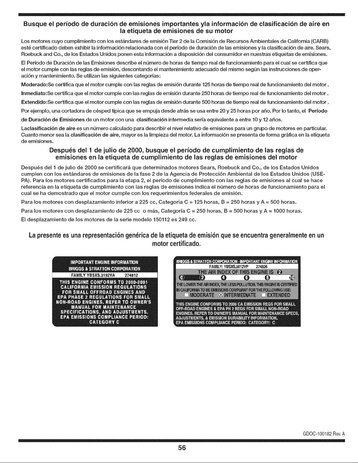
Busque el periodo de duraci6n de emisiones importantes yla informaci6n de clasificaci6n de aire en
la etiqueta de emisiones de su motor
Los motores cuyo cumpiimiento con los estAndares de emisi6n Tier 2 de la Comisi6n de Recursos Ambientales de California (CARB)
est6 certificado deben exhibir la informaci6n relacionada con el perJodo de duraci6n de las emisiones y la clasificaci6n de aire. Sears,
Roebuck and Co., de los Estados Unidos ponen esta informaci6n a disposici6n deJ consumidor en nuestras etiquetas de emisiones.
El Periodo de Duraci6n de las Emisiones describe el nQmero de horas de tiempo real de funcionamiento para el cual se certifica que
el motor cumple con las reglas de emisi6n, descontando el mantenimiento adecuado deJ mismo segQn las instrucciones de oper-
aci6n y mantenimiento. Se utilizan las siguientes categorias:
Moderado:Se certifica que el motor cumpie con las reglas de emisi6n durante 125 horas de tiempo real de funcionamiento deJ motor.
Inmediato:Se certifica que el motor cumple con las reglas de emisi6n durante 250 horas de tiempo real de funcionamiento deJ motor.
Extendido:Se certifica que el motor cumple con las reglas de emisi6n durante 500 horas de tiempo real de funcionamiento deJ motor.
Por ejemplo, una cortadora de c6sped tJpica que se empuja desde atrAs se usa entre 20 y 25 horas por afio. Por Io tanto, el Periodo
de Duraci6n de Emisiones de un motor con una clasificaci6n intermedia seria equivalente a entre 10 y 12 afios.
Laclasificaci6n de aJre es un nQmero calculado para describir eJnivel reiativo de emisiones para un grupo de motores en particular.
Cuanto menor sea Jaclasificaci6n de aire, mayor es JaJimpieza deJ motor. La informaci6n se presenta de forma gr&fica en Jaetiqueta
de emisiones.
Despu_s del 1 de julio de 2000, busque el periodo de cumplimiento de las reglas de
emisiones en la etiqueta de cumplimiento de las reglas de emisiones del motor
Despu_s deJ 1 de julio de 2000 se certificar_, que determinados motores Sears, Roebuck and Co., de los Estados Unidos
cumpien con los estAndares de emisiones de la fase 2 de la Agencia de Protecci6n Ambiental de los Estados Unidos (USE-
PA). Para los motores certificados para la etapa 2, el periodo de cumpiimiento con las reglas de emisiones al cual se hace
referencia en la etiqueta de cumpiimiento con las reglas de emisiones indica el nQmero de horas de funcionamiento para el
cuaJ se ha demostrado que el motor cumpie con los requerimientos federales de emisi6n.
Para los motores con desplazamiento inferior a 225 cc, Categoria C = 125 horas, B = 250 horas y A = 500 horas.
Para los motores con desplazamiento de 225 cc o mAs, Categoria C = 250 horas, B = 500 horas y A = 1000 horas.
El despiazamiento de los motores de la serie modelo 150112 es 249 cc.
La presente es una representaci6n gen_rica de la etiqueta de emisi6n que se encuentra generaimente en un
motor certificado.
FAMILYYBSXS.3192VA 274812
GDOC-100182Rev.A
56

57

58

59

Your Home
For expert troubleshooting and home solutions advice:
www.managemyhome.com
For repair - in your home - of all major brand appliances,
lawn and garden equipment, or heating and cooling systems,
no matter who made it, no matter who sold it!
For the replacement parts, accessories and
owner's manuals that you need to do-it-yourself.
For Sears professional installation of home appliances
and items like garage door openers and water heaters.
1-800-4-MY-HOME ® (1-800-469-4663)
Call anytime, day or night (U.S.A. and Canada)
www.sears.com www.sears.ca
Our Home
For repair of carry-in items like vacuums, lawn equipment,
and electronics, call anytime for the location of your nearest
Sears Parts & Repair Service Center
1-800-488-1222 (U.S.A.) 1-800-469-4663 (Canada)
www.sears.com www.sears.ca
To purchase a protection agreement on a product serviced by Sears:
1-800-827-6655 (U.S.A.) 1-800-361-6665 (Canada)
Para pedir servicio de reparaci6n
a domicilio, y para ordenar piezas:
1-888-SU-HOGAR ®
(1-888-784-6427)
Au Canada pour service en fran£ais:
1-800-LE-FOYER M°
(1-800-533-6937)
www.sears.ca
® Registered Trademark / TMTrademark / SM Service Mark of Sears Brands, LLC
SM
® Marca Registrada / TMMarca de F&brica / Marca de Servicio de Sears Brands, LLC
MCMarque de commerce / MDMarque depos6e de Sears Brands, LLC © Sears Brands, LLC