INSTRUCTION MANUAL
32 TON LOG SPLITTER
CMXGLXT3200
IF YOU HAVE QUESTIONS OR COMMENTS, CONTACT US.
1-888-331-4569 WWW.CRAFTSMAN.COM
Definitions: Safety Alert Symbols and Words
This instruction manual uses the following safety alert symbols and words to alert you to hazardous situations and your
risk of personal injury or property damage.
DANGER: Indicates an imminently hazardous situation which, if not avoided, will result in death or serious injury.
WARNING: Indicates a potentially hazardous situation which, if not avoided, could result in death or serious injury.
CAUTION: Indicates a potentially hazardous situation which, if not avoided, may result in minor or moderate injury.
(Used without word) Indicates a safety related message.
NOTICE: Indicates a practice not related to personal injury which, if not avoided, may result in property damage.
1
2
3
4
5
7
6
8
9
10
11
12
13
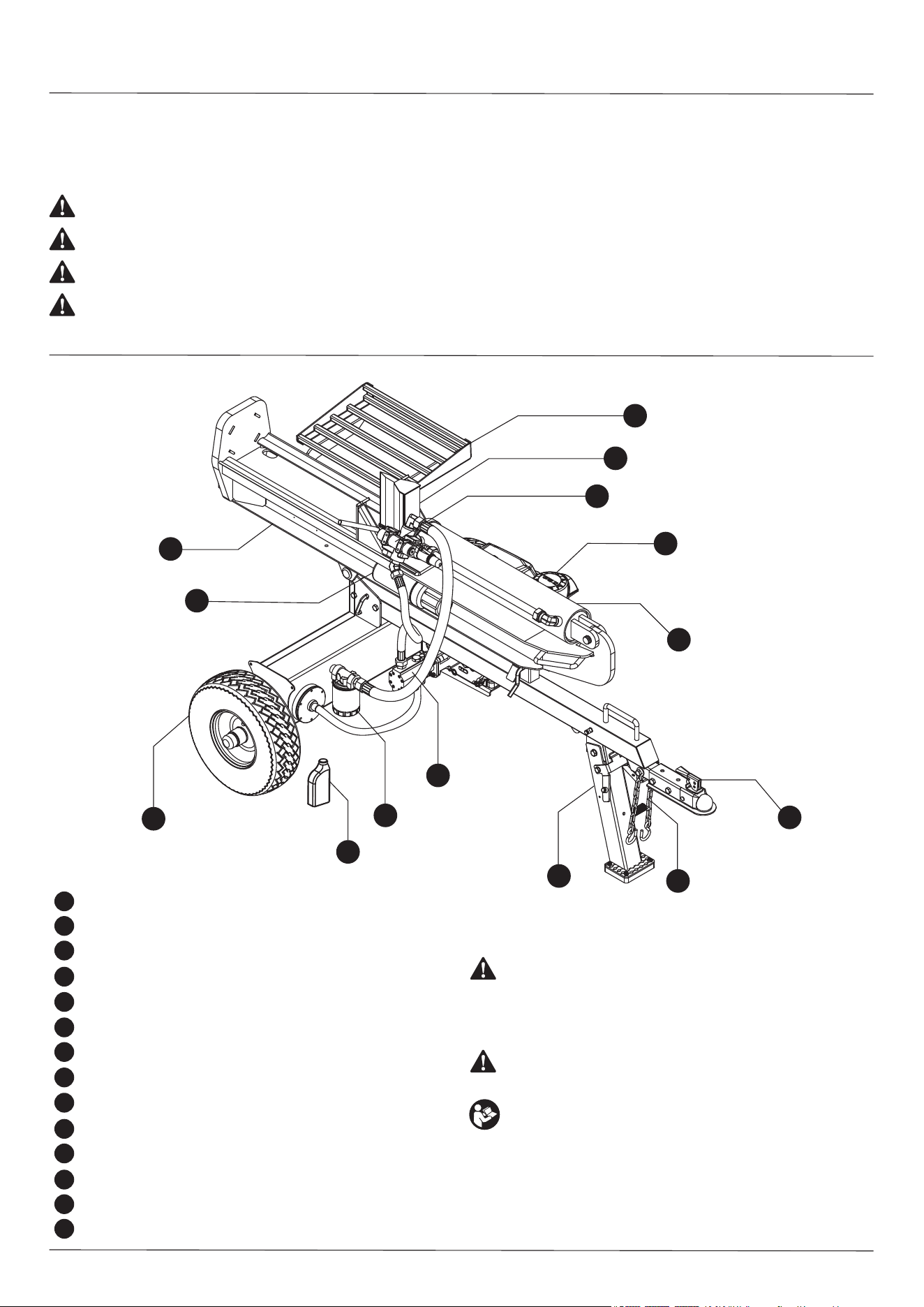
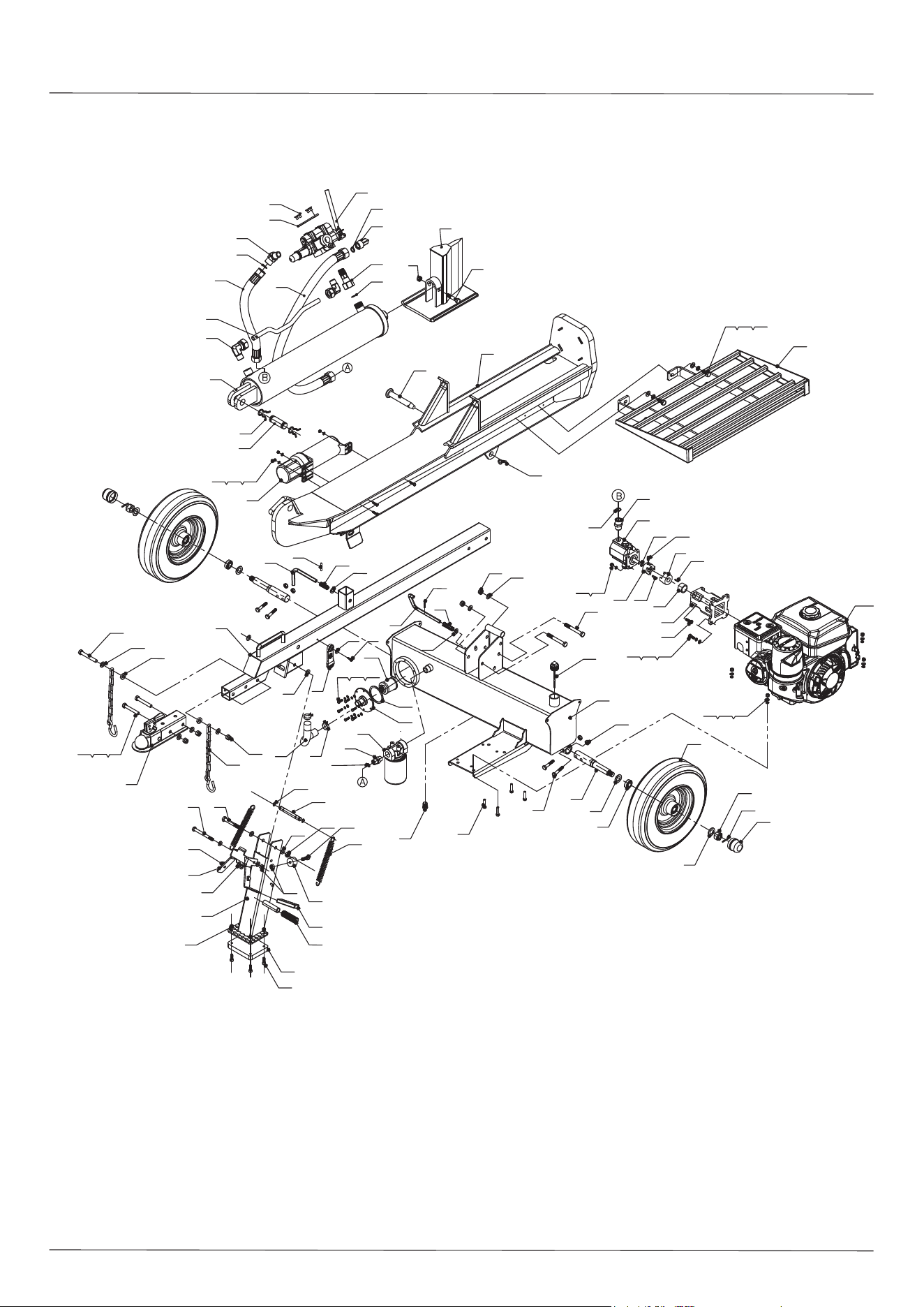
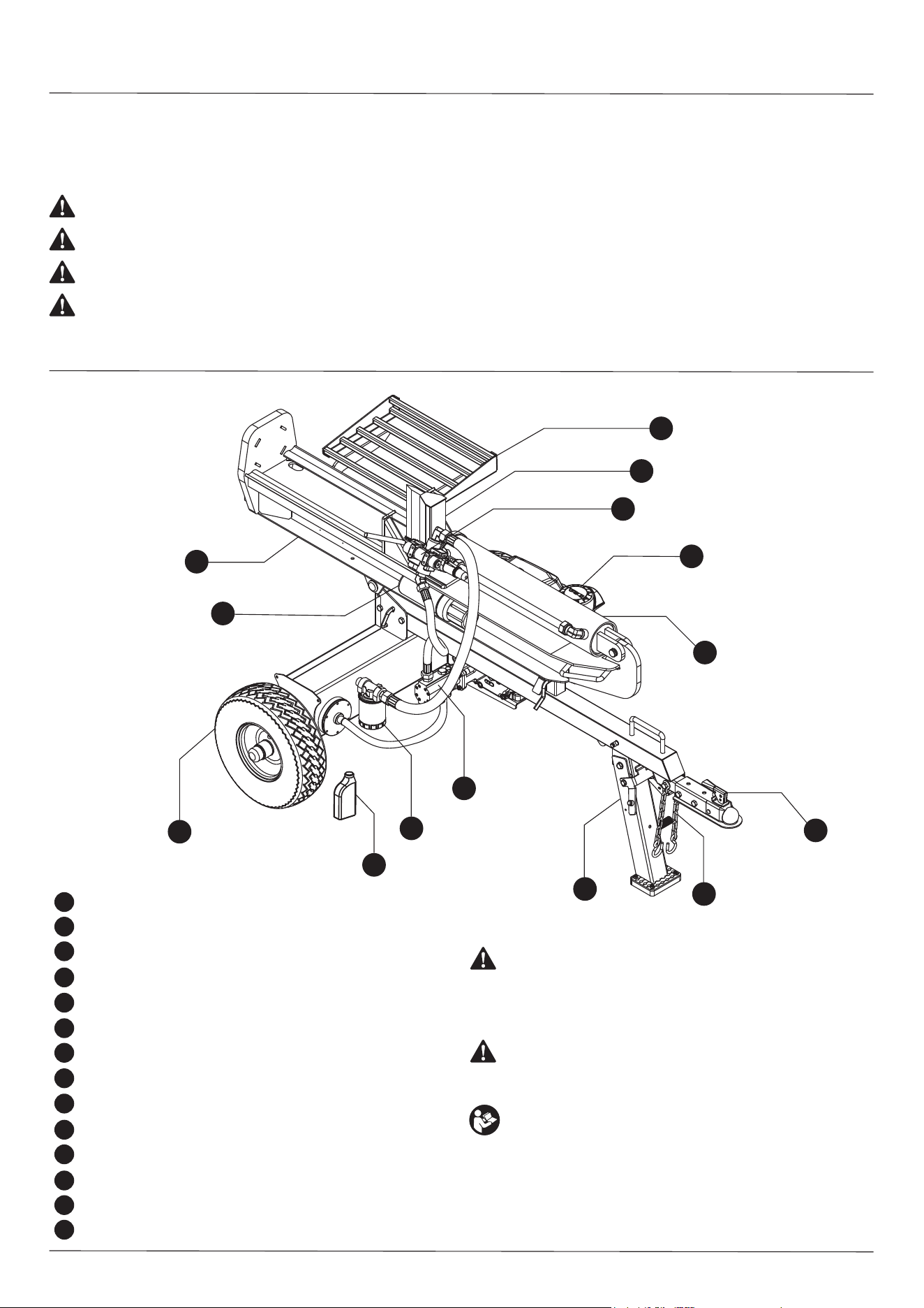
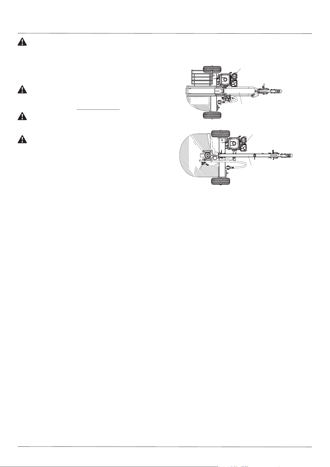
Components
1 2” Ball Coupler
Hydraulic Cylinder
Control Valve
10” Wedge
External Filter
Beam
Engine
Tire / Wheel Assembly
Gear Pump
Support Leg
Safety Chains
Manual Canister
Log Table
2
3
4
5
6
7
8
9
10
11
12
13
WARNING: Read all safety warnings and all
instructions. Failure to follow the warnings and
instructions may result in electric shock, fire
and/or serious injury.
WARNING: Never modify the product or any part
of it. Damage or personal injury could result.
WARNING: To reduce the risk of injury, read the
instruction manual.
If you have any questions or comments about this or
any product, call CRAFTSMAN toll free at:
1-888-331-4569.
2
14
Engine Oil Jug
14
WARNING: IMPORTANT SAFETY INFORMATION
WARNING: Read and understand all instructions and safety information in
this manual and on safety decals before assembling or operating the log splitter.
Failure to understand and follow all instructions and safety information may result
in serious injury or death. Persons who have not read the manual should never
operate the log splitter. A log splitter can be dangerous when assembled and/or
used improperly. Do not operate the log splitter if you have any questions
concerning safe operation. Please call the technical support department at
1-888-331-4569 for answers to any questions.
WARNING:
WARNING:
3
This product can expose you to chemicals including lead and
lead compounds which are known to the State of California to cause cancer and
birth defects or other reproductive harm. For more information, go to
www.P65Warnings.ca.gov
NEVER use the log splitter for any purposes other than splitting
wood. The log splitter is designed only for splitting wood. Using the log splitter for
any other purpose can result in serious injury or death and may void the warranty.
1) GENERAL SAFETY
• ALWAYS keep the operator’s manual in the canister for reference. Review the manual
periodically and as questions arise.
• ALWAYS keep all bystanders and pets a minimum of 10 feet away from your work area
when operating this log splitter. The operator alone should be near the log splitter during
use.
• NEVER activate the control valve until all people are clear of the work area.
• NEVER wear loose clothing or jewelry when operating the log splitter. Keep clothing and
hair away from all moving parts when operating the log splitter.
• NEVER allow adults without proper instruction and operational knowledge to use the log
splitter.
• NEVER operate the log splitter when under the influence of drugs, alcohol or medication
or when otherwise not alert enough to operate the log splitter.
• DO NOT allow children to play on, stand upon, climb on or operate the log splitter at any
time
2) WORK AREA
• NEVER operate the log splitter on wet, icy, slippery or unstable ground.
• NEVER operate the log splitter in an enclosed area. Exhaust fumes contain carbon
monoxide which is deadly poison.
• ONLY operate the log splitter with adequate lighting.
• ONLY operate the log splitter on level ground. Operating on a slope may cause the log
splitter to move and/or logs to fall off the log splitter.
• ALWAYS keep the work area free of debris. Remove any split wood around the log
splitter immediately to avoid tripping.
3) PREPARING LOGS FOR THE SPLITTER
Log ends should be cut as squarely as possible before placing logs on the log splitter.
The square shape of the log helps prevent the logs from moving during splitter operation.
The maximum log length is 26 inches.
4) OPERATION OF THE LOG SPLITTER
ONLY operate the log splitter from the operator zone as shown in the diagram.
Operating the log splitter outside the operator zone can result in serious injury or death.
• ALWAYS chock the wheels to prevent movement of the log splitter while in operation.
• KNOW how to stop the log splitter and disengage the controls before operating it.
• NEVER try to split a log against the grain.
• NEVER try to split two logs at the same time.
• NEVER step over the log splitter during operation.
• NEVER reach or bend over the log splitter to pick up a log.
• NEVER attempt to load the log splitter when the wedge is in motion.
• NEVER place hands or feet between the log and splitting wedge during forward or
reverse stroke as this could result in serious injury or death.
• NEVER use your foot, a rope or any extension device to operate the control lever on
the valve. Only use hands to operate control levers.
• NEVER touch the muffler and other hot areas of the engine. Allow time for the engine
to cool down before touching.
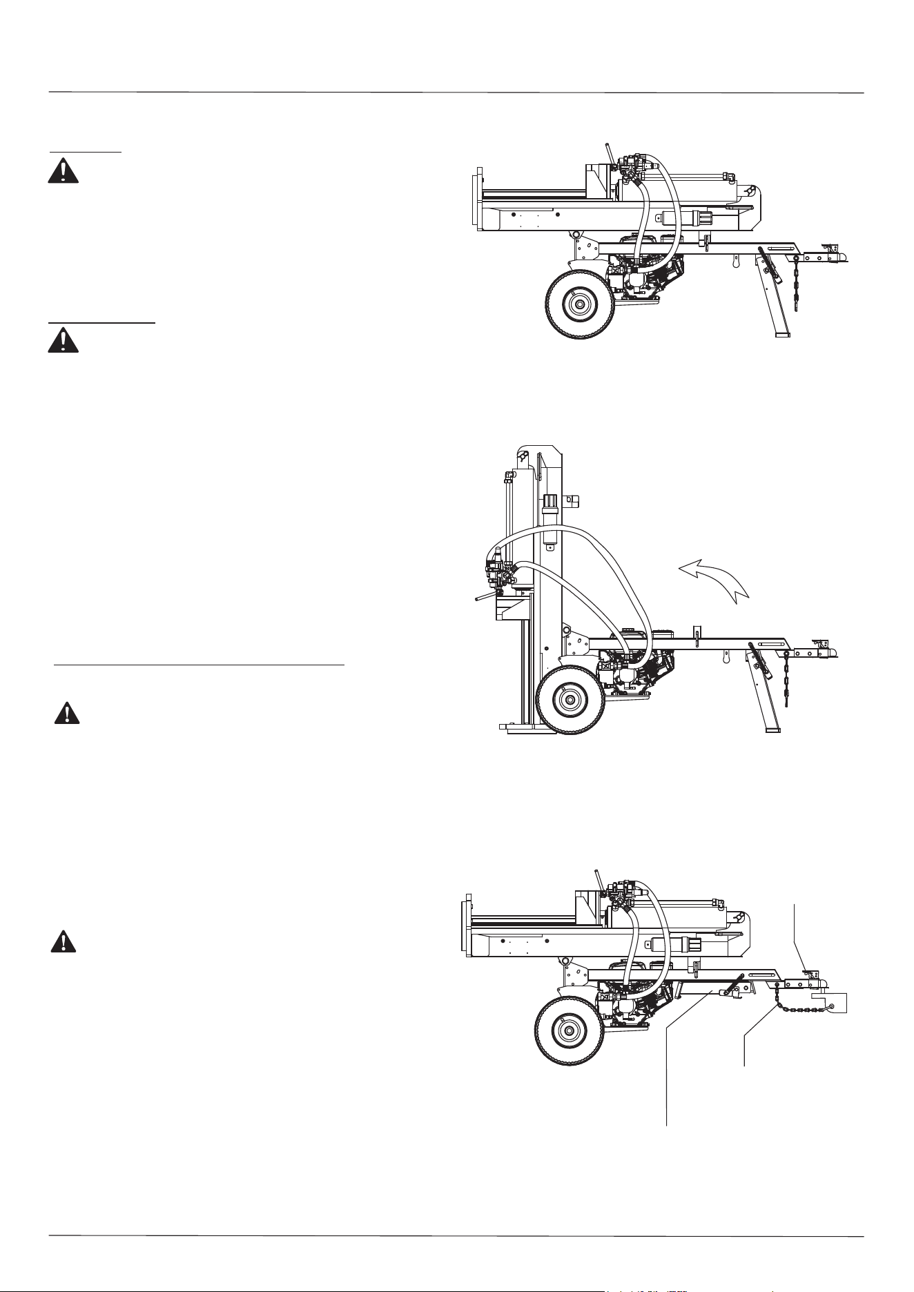
HORIZONTAL POSITION
VERTICAL POSITION
5) GENERAL REPAIR
• NEVER operate the log splitter if it is in poor mechanical condition or in need of repairs.
• NEVER alter/modify the log splitter in any way. Any alterations/modifications may make
the log splitter unsafe and voids the warranty.
• NEVER perform any service or repair on the log splitter without first removing the spark
plug wire.
• NEVER tamper with the engine settings. The maximum engine speed is preset by the
manufacturer and is within safety limits. Refer to the engine’s user manual for the
particular log splitter.
• ALWAYS perform all recommended maintenance procedures before using the log splitter.
• ALWAYS check the level of hydraulic oil and engine oil before operating the log splitter.
• NEVER use hands to remove a stuck log while the log splitter is running.
• ALWAYS replace all damaged or worn parts immediately.
• ALWAYS check regularly that all nuts, bolts, screws, hydraulic fittings and hose clamps
are tight.
• ALWAYS be sure any and all replacement parts meet the manufacturer’s specifications.
6) MAINTENANCE AND STORAGE
• The mechanical and hydraulic systems of the log splitter require careful inspection. Be
sure to replace damaged hydraulic hoses and components.
• NEVER check for leaks of hydraulic fluid by using your hands. Leaking hydraulic fluid under
pressure can potentially penetrate the skin causing SERIOUS INJURY or even DEATH.
Leaks can be safely detected by holding a piece of cardboard over the suspected leak and
looking for discoloration.
• NEVER remove the cap from the hydraulic tank while the log splitter is running. The tank
contains hot oil under pressure which could cause serious injury if released from the tank.
• NEVER adjust the relief valve setting. The pressure relief valve on the log splitter is preset
at the factory. Only a qualified service technician should perform any adjustments.
• ALWAYS immediately seek medical attention if injured by escaping hydraulic fluid. Serious
infections or reactions can develop if proper medical treatment is not administered
immediately.
• ALWAYS check the system is not under any pressure by shutting off the engine and
moving the valve control handle back and forth. Check for pressure before loosening or
removing any hydraulic fitting.
• ALWAYS keep the beam and wedge free of debris buildup.
• ALWAYS check and tighten hardware and assembled parts before operation.
• DO NOT operate the log splitter at night, only during daylight hours.
• NEVER move the log splitter while the engine is running. Turn off the engine before
leaving the log splitter.
• NEVER leave the log splitter running unattended, even for a short period of time.
ENGINE
BEAM
• Before storing make sure the log splitter is clean and dry for years of trouble-free service.
• Lightly lubricate all log splitter surfaces and moving parts to prevent rust.
• Store indoors or protected area during severe weather and winter months.
ENGINE
TOW BAR
ASSEMBLY
OPERATOR
ZONE
OPERATOR
ZONE
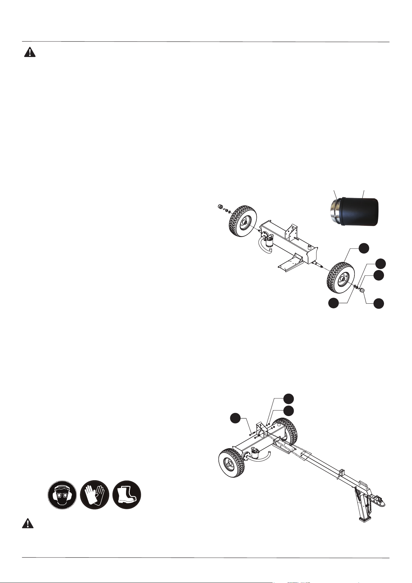
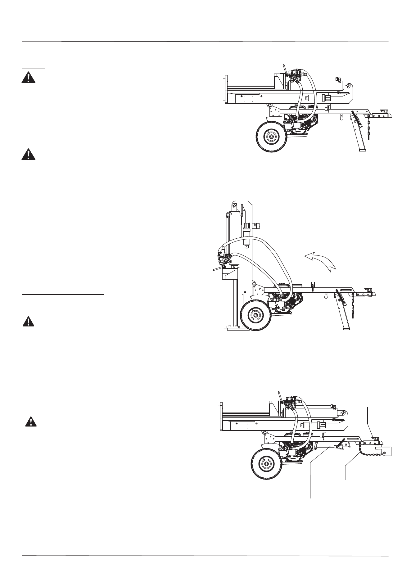
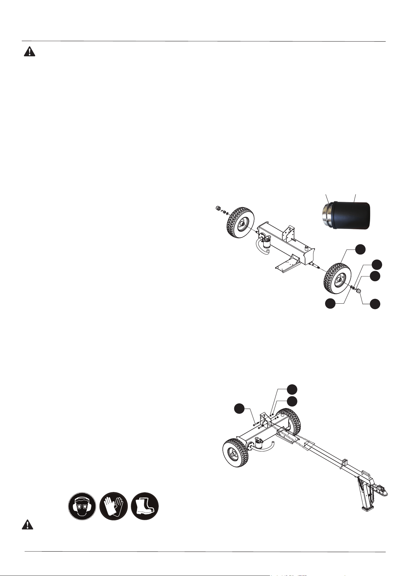
STEP 1: Attach the Wheel
1.1 Remove the cotter pins (71), hex slotted nuts (35) and flat washers (52) from the
wheel axle.
1.2 Attach the wheel to the axle using a Ø20 flat washer (52) and tighten the wheel
with the M20x1.5 hex slotted nut (35). Lock the M20x1.5 hex slotted nut (35) in
place using the Ø4x36 cotter pin (71). Install the axle cap (39) on the end using
rubber hammer.
4
7) FIRE PREVENTION
• ONLY refuel the log splitter in clear areas with no gas fumes and no spilled gas.
• NEVER operate the log splitter near flames, sparks or smoke. Hydraulic oil and gasoline
are flammable and potentially explosive.
• NEVER add fuel while the engine is hot or running. Allow the engine to cool completely
before refueling.
• If gasoline spills, move the log splitter away from the area of the spill and avoid creating
any source of ignition.
• ALWAYS securely replace the gas cap.
• ALWAYS clean wood debris from the muffler area of the engine.
• ALWAYS store gasoline in an appropriate, tightly sealed container. Store the gas
container in a cool, dry place and away from any heat sources.
8) IMPORTANT NOTE RE: SPEAK ARRESTER-REGULATION:
As a precautionary measure against possible flying sparks, always have a Class B fire
extinguisher on hand when operating the log splitter in dry areas. The log splitter is
equipped with an internal combustion engine that generates heat and potential flying
sparks. Only use the log splitter on or near any unimproved, forest-covered, brush-covered
or grass-covered land if the engine’s exhaust system is equipped with a spark arrester in
compliance with any applicable local or state laws. Spark arresters should be effectively
maintained and serviced. In the state of California, a spark arrester is required by law and
other states have similar laws. Federal laws will apply when operating the log splitter on
federal land. Always research and comply with applicable state, local and federal laws
and regulations. A spark arrester muffler is optional and available as an accessory at your
nearest engine dealer.
9) TOWING SAFETY
• NEVER carry cargo or wood on the log splitter.
• NEVER allow anyone to sit or ride on the log splitter.
• NEVER move the log splitter over hilly or uneven terrain without a tow vehicle and/or
adequate help.
• NEVER exceed weight capacity of ball or load limits of coupler.
• NEVER exceed speeds of 45 mph when towing the log splitter. Towing the log splitter
at speeds higher than 45 mph could result in loss of control, damage to the equipment,
and/or serious injury or death. Adjust towing speeds for the terrain and conditions.
Utilize extra caution when towing over rough terrain. Avoid large holes, sharp turns
and steep angles when towing the log splitter.
• ALWAYS attach safety chains when towing the log splitter.
• ALWAYS confirm coupler tightness every time before towing and after towing 50 miles.
• ALWAYS use caution when backing up with the log splitter in tow as it could jackknife.
• ALWAYS accommodate for the added length of the log splitter when turning, parking,
crossing intersections and always when driving while towing the log splitter.
• ALWAYS disconnect the log splitter from the towing vehicle before operating.
• ALWAYS know and comply with all local and state regulations governing towing,
licensing, and lights before towing the log splitter.
• ALWAYS check before towing that the log splitter is correctly and securely attached to
the towing vehicle and that the safety chains are secured to the hitch or bumper of the
vehicle with enough slack to allow for turning. Always use a Class I or above; 2” ball
for connecting to the log splitter.
• ALWAYS replace damaged ball couplers.
• ALWAYS turn the fuel shut off valve on the engine to the “OFF” position before towing
the log splitter. Failure to turn off the engine before towing may flood the engine and
damage engine oil.
ASSEMBLY INSTRUCTIONS
• Screwdriver
• Hammer
• Band Cutter
• 17mm and 19mm Wrenches
• Large Adjustable Wrench
TOOLS REQUIRED (Not Included)
The log splitter is designed only for splitting wood. Using the log splitter for any other
purpose can result in serious injury or death and may void the warranty.
10) PERSONAL PROTECTIVE EQUIPMENT
BEFORE operating the log splitter always be sure to put on appropriate safety gear,
including eye protection (goggles), steel-toed shoes and tight-fitting gloves (without loose
cuffs or draw strings). Also, the use of proper hearing protection (headphones) is required
when operating the log splitter.
WARNING: IMPORTANT SAFETY INFORMATION
Never use the log splitter for any purposes other than splitting wood.
WARNING:
33
35
52
71
39
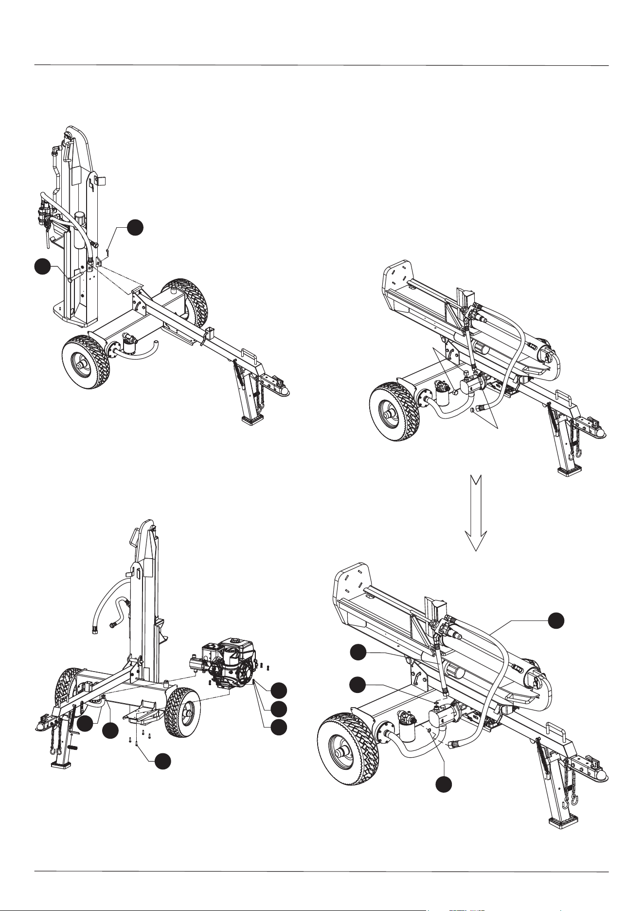
STEP 2: Attach Hydraulic Reservoir and Tow Bar Assembly
2.1 Attach the tow bar assembly to the hydraulic reservoir and secure using M12x100
hex bolts (23), Ø12 flat washers (63) and M12 nylon lock nuts (12) using two
19mm wrenches.
NOTE: Use a black plastic bushing to fix the axle cap like below picture. Please cover
the black bushing onto the axle cap, and use rubber/wooden hammer knocking the end
of the plastic bushing and make the axle cap fixed on wheel.
WARNING: After the slotted nut is tightened, turn
back 1/4 circle to make sure the wheel can rotate
smoothly and freely. Failure to turn the slotted nut
back will cause the wheel not to operate correctly.
63
12
23
Axle Cap Plastic Bushing
5
STEP 5: Attach Hydraulic Hose
5.1 Remove the connector and the hose plugs. Both plugs may be discarded.
5.2 Attach the hydraulic hoses (6 and 15) to the filter assembly and the pump.
The Ø19x2.65 O-Rings (18) are preassembled in the connector.
Keep O-Rings in place during assembly.
A small amount of oil may come out of the hoses when the caps
are removed. To prevent oil dripping on the ground, use a small
pail to catch any oil.
Each connection requires only one O-Ring. Both the hose and the
fitting sides have O-Rings so remove one O-Ring before installing
the hoses. Save the extra O-Ring for possible future use/repair.
Connector Plug
Hose Plug
15
6
18
18
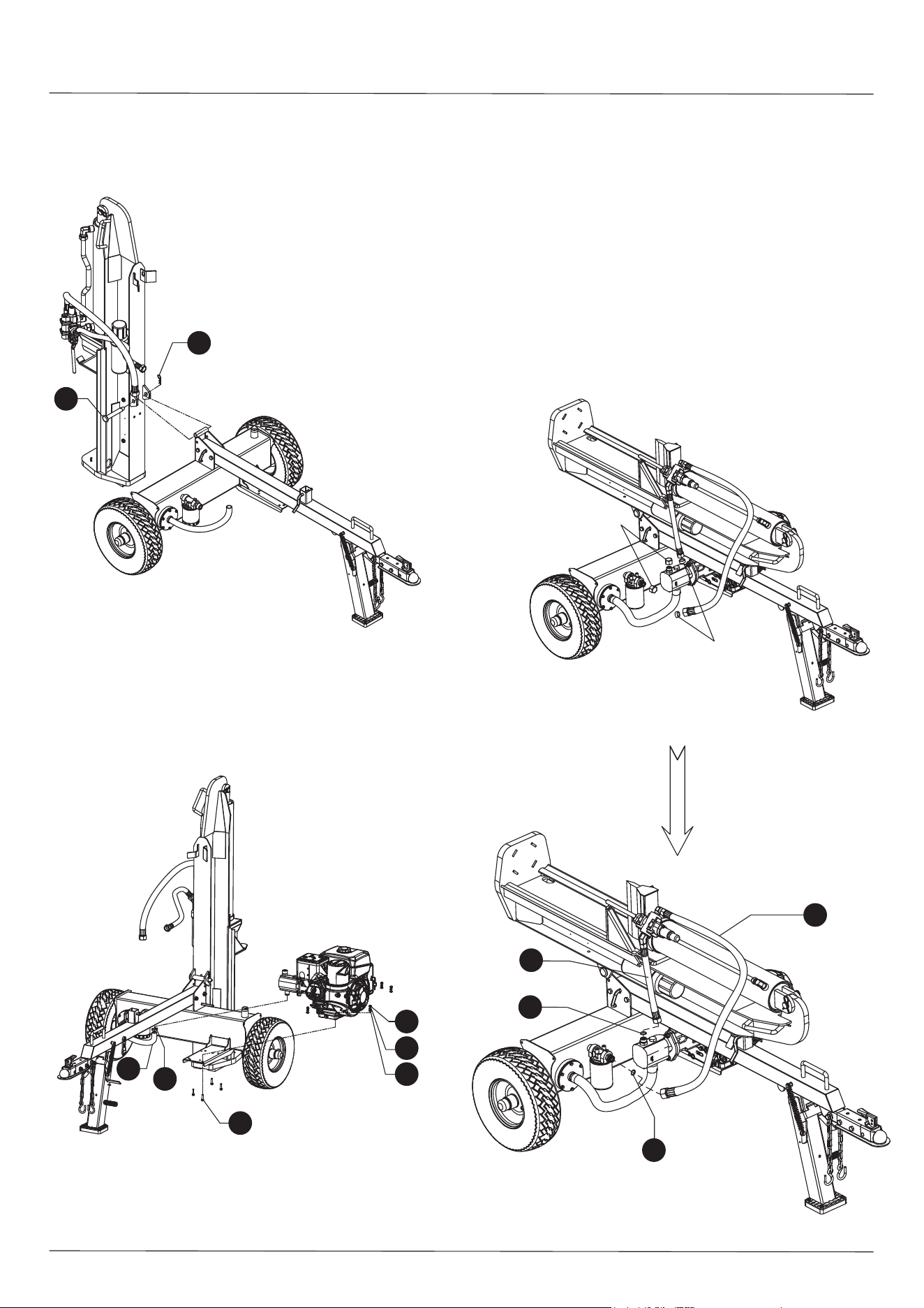
STEP 3: Attach the Beam Assembly
3.1 Remove the hitch pin (17) and R-Clip-pin (20) from the beam.
3.2 Connect the beam and the hydraulic reservoir using the large hitch pin (17)
and the R-Clip-pin (20).
STEP 4: Attach the Engine and Oil Pipe
4.1 Put the engine on the mounting plate tighten with M10x45 hex bolts (44), Ø10
flat washers (75), Ø10 lock washers (74) and M10 nylon lock nuts (73) using
two 17mm wrenches.
4.2 Attach the clear oil pipe (51) to the bottom of the gear pump and secure with
clamp (49).
20
17
51
49
44
75
74
73
6
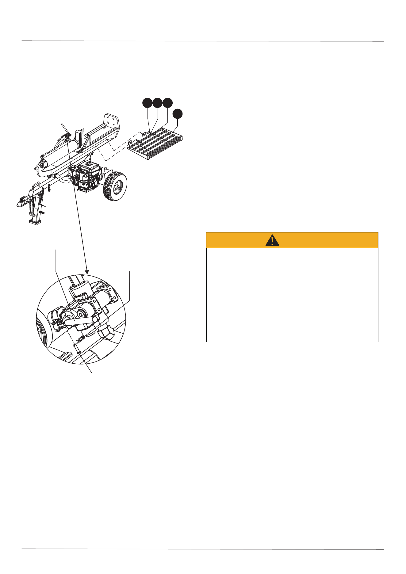
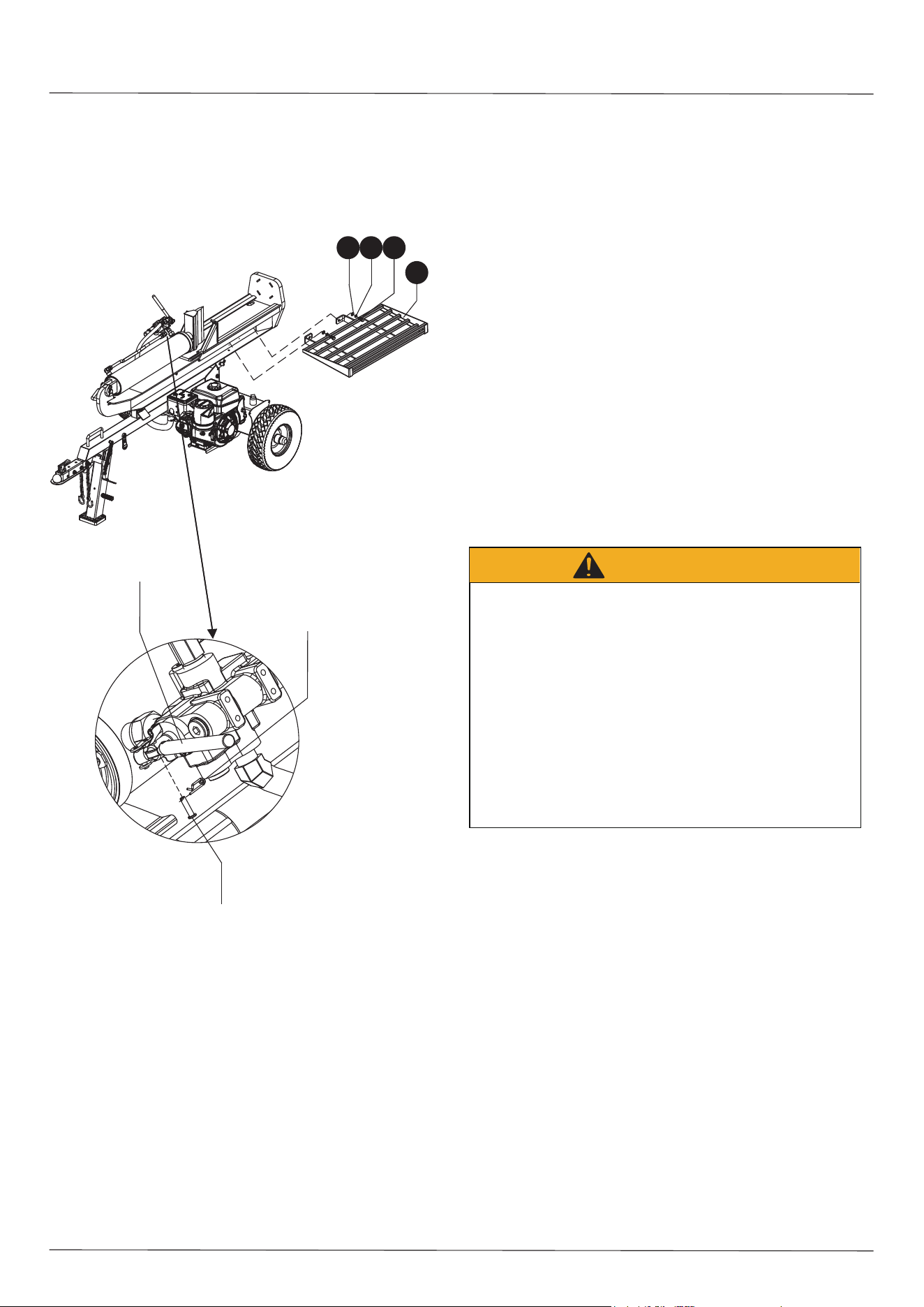
STEP 6: Attach Control Lever and Log Table
6.1 Remove the spring cotter pin and the retaining pin from the control valve.
Rotate the control lever to the vertical position and secure with the
retaining pin and the spring cotter pin.
6.2 Remove the log table hardware from the beam to attach the log table to the
beam. Attach the log table (93) to the beam with the M12x30 hex bolt (70),
Ø12 lock washer (94) and Ø12 flat washer (63) using a 19mm wrench.
7.1 Make sure the log splitter is on a level surface.
7.2 Remove the oil fill cap/dipstick to check the oil level.
7.3 Refer to the separate the engine’s user manual to determine the necessary quantity
of engine oil; add engine oil to the proper level and replace the oil fill cap/dipstick.
7.4 Check the engine oil level daily and add oil as necessary to maintain the proper level.
STEP 7: Add Engine Oil
NOTICE: During the break-in period check the engine oil level often. When initially
using the log splitter the operator should check the engine oil level frequently to ensure
proper function.
DO NOT attempt to crank or start the engine before it has been properly filled with the
recommended type and amount of engine oil. Damage to the log splitter resulting from a
failure to follow these instructions will void the warranty.
Control Level
Spring Cotter Pin
Retaining Pin
9463 70
93
STEP 8: Add Hydraulic Oil
8.1 The log splitter needs to be on a flat level surface before adding the hydraulic oil.
DO NOT remove the hydraulic oil fill cap when the engine is running or hot. Hot oil
can escape causing severe burns. Always allow the log splitter to cool completely
before removing the hydraulic oil cap.
High fluid pressure and temperatures are created inside hydraulic log splitters.
Hydraulic fluid can escape through a pin-size hole and can puncture skin and cause
severe blood poisoning.
Inspect hydraulic systems regularly for possible leaks. Never check for leaks with
your hand while the system is pressurized. Seek medical attention immediately if
injured by leaking fluid.
Make sure all fittings are tight and secure before applying pressure. Relieve system
pressure before servicing.
Make sure the hydraulic hoses do not touch any hot surfaces or cutting areas.
Hoses need to be positioned away from the engine and cutting wedge. To avoid
serious bodily injury always inspect the hoses before operating the log splitter.
WARNING
8.2 Remove the oil cap from the hydraulic oil tank.
8.3 Add 5 gallons of hydraulic oil AW32, AW46 & universal hydraulic oil are all
acceptable types of fluid.
8.4 Start the engine and use the control lever to extend and retract the wedge several
times to remove air from the lines.
8.5 With the wedge retracted, check the hydraulic oil level again and fill if necessary.
8.6 To enhance engine start up, automatic transmission fluid can be used when
operating in temperatures below 32 degrees.
7
ENGINE OIL RECOMMENDATIONS
277cc Kohler Engine
a) Check that “ON”/“OFF” switch is in the “ON” position.
b) Move the throttle lever to “FAST”. Always operate the engine with throttle lever in the
“FAST” position.
c) Move choke control lever to “CHOKE” position.
d) Grasp rope handle and pull slowly to the point of resistance. Once resistance is felt pull
rapidly to start the engine and to avoid engine kickback.
e) After allowing the engine to warm up, move the choke control lever slowly toward “RUN”.
In cold weather give the engine extra time to warm up before slowly moving the choke
lever toward “RUN”. Operate with the choke lever in the “RUN” position.
f) To stop engine, move the “ON”/“OFF” switch to the “OFF” position.
9.1 Use only clean, fresh, regular unleaded fuel with a minimum 87 octane rating.
9.2 DO NOT mix oil with fuel.
9.3 Remove the fuel cap and slowly add fuel to the tank. DO NOT overfill and allow
for approximately a ¼ inch of space for fuel expansion.
9.4 Tightly screw on the fuel cap and clean/wipe away any spilled fuel.
STEP 9: Add Gasoline to the Engine
Fuel and fuel vapors are highly flammable and extremely explosive.
Fire or explosion can cause severe burns or death.
Unintentional startup can result in entanglement, traumatic amputation or laceration.
Only use regular unleaded gasoline with a minimum 87 octane rating.
DO NOT mix oil and gasoline together.
Fill tank approximately ¼” below the top of the tank to allow for fuel expansion.
DO NOT fill fuel tank indoors or when the engine is running or hot.
DO NOT light cigarettes or smoke when filling the fuel tank.
WARNING
OPERATING INSTRUCTIONS
WARNING: Read and understand all instructions and safety information in this
manual and on safety decals before assembling or operating the log splitter.
Failure to understand instructions and safety information could result in serious
injury or death. Do not allow anyone to operate the log splitter who has not read
this manual. A log splitter can be dangerous if assembled or used improperly.
Do not operate this log splitter if you have any questions concerning safe
operation. Call our technical support department at 1-888-331-4569 for answers
to any questions.
CAUTION: DO NOT START/ RUN THE ENGINE BEFORE CHECKING THE OIL IN
THE HYDRAULIC RESERVOIR AND THE OIL IN THE ENGINE.
The engine comes with 10W-30 oil. Refer to the engine’s user manual for information
regarding proper oil temperature ranges and grades to use. Engine oil capacity is 37.2 ounces.
After the hydraulic reservoir and the engine crankcase are filled with oil, start the engine.
The hydraulic pump should prime itself. With the engine running, move the control valve lever
toward the foot plate. This will cause the cylinder to extend and expel air. When the cylinder
is fully extended, retract it. Repeat this procedure several times. After this procedure check oil
level again. If the tank is overfilled it tends to expel oil from the breather cap when the cylinder
is retracted. Cycle the cylinder again until it maintains a constant speed which indicates all the
air has been expelled from the cylinder.
STARTING INSTRUCTIONS
Refer to the Kohler engine’s user manual for complete information on starting, maintenance
and specifications.
CAUTION: TURN FUEL SHUT OFF VALVE TO THE “OFF” POSITION BEFORE
TOWING.FAILURE TO DO SO MAY RESULT IN FLOODING THE ENGINE AND
DESTROYING ENGINE OIL.
NOTE:
OPERATION
WARNING: Review safety information related to operation of the log splitter
on page 3 and 4 of this manual. Make sure that you have the recommended
personal protective equipment described on page 4.
1) Set up the log splitter in a clear, level area and chock the wheels.
2) For horizontal operation, place a log on the beam against the foot plate. Make sure the log
is securely on the foot plate and up against the beam. To split wood in the vertical position,
release the pin on the beam latch located near the front end of the beam. Tilt the beam up
until the foot plate is sitting squarely on the ground and the log splitter is stable. Place the
log on the foot plate up against the beam. When the beam is returned to the horizontal
position make sure the beam latch pin is secure.
3) Move control valve handle so that the cylinder will drive the wedge into the log. Extend the
cylinder until the log splits or until it reaches the end of its stroke. If the log has not
completely split after the cylinder has reached the end of its extension, retract the cylinder.
IMPORTANT: Leaving the valve in the “actuate” position at the end of the stroke can
accelerate wear on the hydraulic component. Do not split logs with unsquared ends.
NOTICE: For operation in wooded areas, obtain a spark arrestor for the exhaust system.
Consult the engine operating and maintenance manual and check with your authorized
Kohler service center. Also see Fire Prevention on page 4 of this manual.
The engine maximum governed speed is preset at the factory at 3750±100
RPM load speed. When splitting wood, the throttle should be set at the maximum
speed in order to generate the horsepower required for the pump.
DANGER
Log splitter engine exhaust contains carbon monoxide, a colorless, odorless, poison
gas.
Breathing carbon monoxide may cause nausea, dizziness, fainting or death. If you
start to feel dizzy or weak, immediately cease operation and get to fresh air and seek
medical attention.
Log splitters should be operated only outdoors and in well-ventilated areas.
DO NOT operate the log splitter inside any building, enclosure or compartment.
DO NOT allow exhaust fumes to enter a confined area through windows, doors, vents
or other openings.
DANGER CARBON MONOXIDE, using a log splitter indoors CAN KILL YOU IN
MINUTES.
8
TOWING
WARNING: The log splitter is equipped with pneumatic tires, a Class I or above
coupler (2 in. diameter ball required) and safety chains. Before towing, the safety chains
must be secured to the hitch or bumper of the vehicle. Local regulations should be
checked regarding licensing, lights, towing, etc. Before towing, turn the fuel shut off valve
on the engine to the “OFF” position. Failure to turn off the engine before towing may flood
the engine. Do not exceed 45 mph when towing the log splitter. Also see Towing Safety
on page 4 of this manual.
MAINTENANCE
Shut off splitter and wait until it is completely cool before performing
any maintenance. The log splitter should be on a level surface with wheels properly
chocked before maneuvering on or around the log splitter.
1) Consult the operating and maintenance instructions of the engine’s manufacturer for
engine care and maintenance.
2) Always check the oil level of the hydraulic reservoir before operation. Operating the
log splitter without an adequate oil supply will cause severe damage to the pump.
3) Change the spin on filter after the first 25 hours of operation. There after change the
spin on filter every 100 hours or seasonally, whichever comes first.
4) To drain the hydraulic oil, remove the drain plug from the bottom of the tank. The drain
plug is located just to the right of the oil filter.
5) If the wedge needs to be sharpened, it can be removed and sharpened.
6) Clean the breather cap after every 25 hours of operation. When operating in dusty
conditions the breather cap should be cleaned more frequently. To clean, first remove
the breather cap from the tank, then flush with solvent and blow out the cap with air.
7) Also see General Repair and Maintenance Safety on page 3 of this manual.
8) All replacement parts must meet manufacturer’s specifications.
9) Grease Wheel Bearings and tighten all hardware seasonally.
OPERATING INSTRUCTIONS
WARNING:
1. Clean the log splitter thoroughly before storage.
Prepare the log splitter for storage at the end of the season or if the log splitter will not
be used for 30 days or more.
STORING THE LOG SPLITTER
WARNING: Never store the log splitter with fuel in the fuel tank inside of any
building where fumes could contact an open flame or spark, or where
ignition sources are present, such as hot water and space heaters, furnaces,
clothes dryers, stoves, electric motors, etc.
NOTE: The use of pressure washers and/or garden hoses to clean the log splitter is
NOT recommended. Using them to clean may cause damage to the bearings or the
engine. In general, using water to clean the log splitter can shorten machine life and
reduce serviceability.
2. Wipe down the entire log splitter with an oiled rag to prevent rust, especially on
the push plate and the beam.
3. Completely drain the fuel tank.
WARNING: Never smoke while around or when handling fuel. Always drain fuel
into an approved container while outdoors and away from open flames and other
potential sources of ignition. Be sure that engine is cool before draining the fuel.
4. Start the engine and let it run until the fuel lines and carburetor are empty.
5. Remove the spark plug. Holding a rag over the cylinder hole, pour approximately
a 1 ounce of engine oil into the cylinder and crank slowly to evenly distribute the oil.
6. Replace the spark plug.
7. Do not store and reuse gasoline from one season to another.
8. Replace any gasoline can if it starts to rust. Using gasoline containing rust and/or
dirt will cause operational problems for the log splitter.
9. Always store the log splitter in a clean, dry area, preferably inside and safe from
weather. Do not store the log splitter close to any corrosive materials, such as
fertilizer.
NOTE: If storing the log splitter in an unventilated or metal storage shed, be certain to
rust-proof the equipment by coating with a light oil or silicone.
VERTICAL POSITION
1. Pull beam lock pin
2. Rotate the beam in the upright
position by lifting the beam.
Upright position for splitting large logs.
FOR VEHICLE TOWING
Press handle down
and lock tightly.
Rotate the Support
Leg to the up position.
Hook safety chains
to towing vehicle.
HORIZONTAL POSITION

9
TROUBLESHOOTING
For further technical support please contact:
YTL International Inc.
17517 Fabrica Way Suite H
Cerritos, CA 90703
Phone: (888) 331-4569
Website: www.CRAFTSMAN.com
Problem Cause Solution
Engine will not start
Engine switch in “OFF” position Move switch to “ON” position
Fuel shut-off valve in “OFF” position Move valve to “ON” position
No fuel Add fuel
Faulty spark plug Replace the spark plug
Spark plug is disconnected Connect the spark plug
Unit is loaded during start up
Move valve handle back and forth,
remove load
Engine shuts off during
operation
Out of fuel Fill the fuel tank
Low oil level Fill the crankcase to the proper oil level
Wedge movement is slow or
erratic
Air in the hydraulic oil system
Purge air by extending and retracting the
wedge several time until motion is smooth
Debris lodged in beam guides Clear debris from beam
Low hydraulic oil Check oil level and add as needed
Wedge will not extend or
retract
Faulty control valve Contact customer service
Faulty hydraulic pump Contact customer service
Low hydraulic oil Check oil level and add as needed
Wedge does not auto-return
Low hydraulic oil Check oil level and add as needed
Faulty control valve Contact customer service
Excessive bouncing while towing
Under-inflated tires Inflate tires to proper pressure level
Over-inflated tires Inflate tires to proper pressure level
Log Splitter Parts and Service:
Toll Free 1-888-331-4569
FREE WARNING LABEL REPLACEMENT: If warning labels become illegible or are missing, call 1-888-331-4569 for a free replacement.

10
SPECIFICATIONS
Maximum Splitting Force............................................................................32 Tons
Cycle Time............................................................................................10 Seconds
(Note: Cycle time may vary given mechanical and environmental factors; the
published cycle time is for ideal conditions)
Wedge Height ......................................................................... 10” Hardened Steel
Gear Pump .................................................................................16 GPM, 2-Stage
Hydraulic Oil ......................................... AW32, AW46 and Universal Hydraulic Oil
Hydraulic Capacity.............................................................................. 7.55 Gallons
Maximum Log Length ........................................................................................26”
Hydraulic Cylinder.................................................................................4-3/4” x 24”
Maximum Pressure.................................................................................. 3698 PSI
Wheel Size................................ 6.5-8 wheel with 18” outside diameter D.O.T tires
Hitch Type....................................................................................... 2” Ball Coupler
Maximum Towing Speed............................................................................ 45 MPH
Manual Start Engine ..................................................................................... 277cc
NOTE: For Engine Details Refer to the Engine’s User Manual.
11
DRAWING
22
73
19
52
58
71
56
57
39
44
53
35
33
23
54
42
46
40
25
63
11
63
38
12
18
14
72
20
946370
93
17
16
13
91
88
89
81
85
86
90
87
30
59
75
73
95
79
64
12
63
84
83
80
23
12 63 65
12
49
51
18
61
48
47
63
4568 43
76
7877
37
66
63
67
60
38
54
96
63
9
2
4
45 43 92
5
3
7
18
6
15
18
62
10
18
36
50
8
32
73
7475
21
3431
55
29
27
28
6926
90
31
82
24
41 1

12
PARTS LIST
Ref# Drawing No. Description Qty.
1 9121-06010-FH M6x10 Inner Hex Cone Point Set Screw 1
2 LSP3200-08000-0CG Cylinder 1
3 LSP3200-00002 Metal Tube 1
4 LSP25-00005-DX R Pin 2
5 LSP25-00004-DX Cylinder Pin 1
6 LSP3200-00005 Hydraulic Hose (valve-gear pump) 1
7 LSP3200-04000 Connector 2
8 LSP3200-00012 Control Valve 1
9 LSP3200-03000 Combination Connector 1
10 LSP3200-00003-DX 130°Joint 1
11 LSP25-00006-DX Pin 1
12 9206-12000-DX M12 Nylon Lock Nut 6
13 LSP3200-02000 Wedge 1
14 9101-14080-DX8.8 M14x80 Hex Bolt 1
15 LSP3200-00006 Hydraulic Hose (valve-external filter) 1
16 LSP3200-01000-0CR Beam 1
17 LSP3700-00001-DX Hitch Pin 1
18 9901-19×2.65 Ø19x2.65 O Ring 5
19 LSP25-00010-DX Oil Plug 1
20 LSP25-00012-DX R Pin 1
21 9101-08030-DX8.8 M8x30 Hex Bolt 4
22 LSP3200-00001-DX Gear Pump Connector 1
23 9101-12100-DX8.8 M12x100 Hex Bolt 3
24 LSP35-02006 Gear Pump 13/3.0 1
25 LSP25-13000 Fill Plug 1
26 LSP35-02003 Gear Pump Coupling 1
27 LSP30A-10004 Engine Coupling 1
28 LSP30A-10002-DX Engine Axle Sleeve 1
29 LSP30A-10001 Gear Pump Stand 1
30 LSP3700-04000 Front Support Leg Assembly 1
31 9306-08000-DX Ø8 Lock Washer 12
32 LSP30A-10003 Engine 1
33 LSF3000-18000-G Wheel Assembly 2
34 9301-08000-DX Ø8 Flat Washer 8
35 LSP25-00020-FH M20x1.5 Hex Slotted Thin Nut 2
36 LSP3200-00004-DX Angle Connector 1
37 LSP30-00007 Oil Filter 1

PARTS LIST
13
Ref# Drawing No. Description Qty.
38 9404-03030-DX Ø3x30 Cotter Pin 2
39 LSP25-00009-DX Axle Cap 2
40 LSP30-00006 Rubber Washer 1
41 LSP25-10008-FH Steel Wire Snap Ring for Shaft 1
42 LSP3700-02000 Hydraulic Reservoir 1
43 9301-06000-DX Ø6 Flat Washer 9
44 9101-10045-DX8.8 M10x45 Hex Bolt 4
45 9101-06020-DX8.8 M6x20 Hex Bolt 9
46 LSP30-15000 Filter Mounting Plate 1
47 LSP25-09000 Spin-on Filter 1
48 LSP4001-00008-DX Connector 1
49 LSP25-00011-DG Clamp 2
50 LSP2700-00005 Plate 1
51 LSP3200-00011 Clear Oil Pipe 1
52 9301-20000-DX Ø20 Flat Washer 2
53 LSP3700-00003 Wheel Axle 2
54 LSP25-00003-DX Spring 2
55 9101-08025-DX8.8 M8x25 Hex Bolt 4
56 LSP25-14002 Oil Seal 2
57 L44643 Tapered Roller Bearing 4
58 9101-10055-DX8.8 M10x55 Hex Bolt 4
59 LSP2501-09000 Support Lock Weldment 1
60 LSP3700-03000-0CR Tow Bar Assembly 1
61 LSP25-11000-DX Chain 2
62 9110-08010-DX M8x10 Screw 2
63 9301-12000-DX Ø12 Flat Washer 14
64 Z103 2” Coupler 1
65 9101-12080-DX8.8 M12x80 Hex Bolt 2
66 LSP25-00015-DX Thick Washer 2
67 9101-12090-DX8.8 M12x90 Hex Bolt 1
68 9306-06000-DX Ø6 Lock Washer 6
69 LSP25-10009 Gear Pump Flat Key 1
70 9101-12030-DX8.8 M12x30 Hex Bolt 2
71 9404-04036-DX Ø4x36 Cotter Pin 2
72 9206-14000-DX M14 Nylon Lock Nut 1
73 9206-10000-DX M10 Nylon Lock Nut 10
74 9306-10000-DX Ø10 Lock Washer 4

14
PARTS LIST
Ref# Drawing No. Description Qty
75 9301-10000-DX Ø10 Flat Washer 8
76 LSP2501-00011 Connecting Belt 1
77 9302-06000-DX Ø6 Large Flat Washer 1
78 9199-06325-CD Hex Flange Head Tapping Screw ST6.3×25 1
79 9304-01500 Ø15 Circlip for Shaft 2
80 LSF3000-00003 Spring Pin 1
81 LSF3000-00006 Spring for Support Leg 2
82 LSP25-10010 Engine Flat Key 1
83 9101-10110-DX8.8 M10x110 Hex Bolt 1
84 9105-10030-DX M10x30Hex Socket Round Head Screw 1
85 LSF3000-00050 Rubber Mat 1
86 N560-00019 Handle Sleeve 1
87 E050-05002 Gum Cover 1
88 LSF3000-00051 Elastic Cushion 1
89 9105-08025-DX M8x25 Hex Socket Round Head Screw 4
90 9206-08000-DX M8 Nylon Lock Nut 12
91 LSP30MD-02000 Manual Canister 1
92 9206-06000-DX M6 Nylon Lock Nut 3
93 LSP3001-06000-0CR Log Table 1
94 9306-12000-DX Ø12 Lock Washer 2
95 LSF3000-00004 Spring Pendant 2
96 LSP25-00008-DX Pin 1

LIMITED WARRANTY
Duration of Warranty
For 3 years from the date of purchase, YTL International will replace or repair defects in material and workmanship for the original purchaser of the log splitter. For 2 years, the engine
warranty is covered per the engine manufacturer’s warranty. For 1 year from date of purchase, YTL International will replace the hydraulic system component parts. The warranty will
not apply to any unit which was not assembled correctly, misused, overloaded or which has been used or operated contrary to our instructions, or which has been repaired or altered
by anyone other than an authorized service representative.
Warranty Exclusions
The warranty does not cover cosmetic defects such as paint and decals. The warranty excludes components that wear out with ordinary use over time, such as tires. The warranty does
not cover failures or problems due to acts of God and events or forces beyond the control of the manufacturer.
Normal Wear Exclusions
The log splitter needs periodic service to perform well. The warranty does not cover repair when normal use has exhausted the life of a part or the equipment as a whole.
Installation, Use and Maintenance Exclusions
The warranty does not apply to parts and/or labor if the log splitter has been misused, neglected, involved in an accident, abused, loaded beyond its’ limits, modified or assembled
incorrectly. Normal maintenance is not covered under the warranty.
Limits of Implied Warranty and Consequential Damage Exclusions
YTL International disclaims any obligation to cover any loss of time, use of this product, freight, or any incidental or consequential claim by anyone incurred from using the log splitter.
THIS WARRANTY IS IN LIEU OF ALL OTHER WARRANTIES, EXPRESS OR IMPLIED, INCLUDING WARRANTIES OF MERCHANTABILITY OR FITNESS FOR A PARTICULAR
PURPOSE.
An exchanged log splitter unit will be subject to the original warranty date. The length of the warranty governing the exchanged unit will be calculated from the purchase date of the
original unit. The warranty gives you certain legal rights which may change from state to state. Your state may also have other rights you may be entitled to that are not listed within
this warranty.
Product manufactured by: YTL International Inc.
Producto fabricado por: YTL International Inc.
Produit fabriqué par: YTL International Inc.
LICENSEE NAME: YTL International Inc.
LICENSEE ADDRESS: 17517 Fabrica Way Suite H Cerritos, CA 90703
For product, service or warranty information contact us at:
Para obtener información sobre el producto, el mantenimiento
o la garantía, comuníquese con nosotros en:
Pour obtenir de l'information sur les produits, les réparations ou
la garantie, prière de nous contacter au:
U.S. & Canada Only • É.-U. et Canada seulement
www.CRAFTSMAN.com • 888-331-4569
CRAFTSMAN®
is a registered trademark of Stanley Black & Decker, Inc., used under license.
es una marca registrada de Stanley Black & Decker, Inc., utilizada bajo licencia.
est une marque déposée de Stanley Black & Decker, Inc., utilisée sous licence.
MANUAL DE INSTRUCCIONES
Divisor de leños de 32 toneladas
CMXGLXT3200
SI TIENE DUDAS O COMENTARIOS, CONTÁCTENOS.
1-888-331-4569 WWW.CRAFTSMAN.COM
Definiciones: Términos y símbolos con alertas de seguridad
Este instructivo utiliza los siguientes términos y símbolos con alertas de seguridad para advertirle de situaciones de peligro
y riesgos de lesión personal o daños materiales.
PELIGRO: indica una condición peligrosa inminente que, si no se evita, causará la muerte o lesiones graves.
ADVERTENCIA: indica una condición peligrosa potencialmente que, si no se evita, podría causar la muerte o lesiones graves.
PRECAUCIÓN: indica una condición peligrosa potencialmente que, si no se evita, podría causar lesiones menores o moderadas.
(Sin palabras) Indica un mensaje relacionado con la seguridad.
Componentes
1 Acoplador de bola de 2 pulgadas
Cilindro hidráulico
Válvula de control
Cuña de 10 pulgadas
Filtro externo
Viga
Motor
Conjunto de rueda y neumático
Bomba de engranajes
Pata de soporte
Cadenas de seguridad
Recipiente para el manual
Tabla de registro
2
3
4
5
6
7
8
9
10
11
12
13
ADVERTENCIA: Lea todas las advertencias de seguridad
y todas las instrucciones. El incumplimiento de las
advertencias e instrucciones podría causar choque
eléctrico, incendio o lesiones graves.
ADVERTENCIA: Nunca modifique el producto o
cualquiera de sus componentes. Podría causar
daños o lesiones personales.
ADVERTENCIA: Para reducir el riesgo de lesión, lea
el manual de instrucciones.
Si tiene preguntas o comentarios sobre este producto
o cualquier otro, llame a la línea telefónica gratuita de
CRAFTSMAN: 1-888-331-4569.
17
Jarra de aceite del motor
14
AVISO:
Indica una práctica no asociada con lesiones personales que, si no se evita, podría causar daños materiales.
1
2
3
4
5
7
6
8
9
10
11
12
13
14
ADVERTENCIA: INFORMACIÓN IMPORTANTE
SOBRE LA SEGURIDAD
ADVERTENCIA: Lea y comprenda toda las instrucciones y la información
de seguridad en este manual y en las etiquetas adhesivas de seguridad antes de
ensamblar y usar este divisor de leños. Su incomprensión podría causar lesiones
graves o la muerte. No permita que ninguna persona que no haya leído este manual
use este divisor de leños. Un divisor de leños puede ser peligroso si no se ensambla
o usa de manera correcta. No use este divisor de leños si tiene preguntas sobre
cómo usarlo de manera segura. Llame a nuestro departamento de asistencia
técnica al teléfono 1-888-331-4569 para que respondan sus preguntas.
ADVERTENCIA:
ADVERTENCIA:
18
Este producto puede exponerle a sustancias químicas,
incluyendo plomo y componentes de plomo, que el estado de California considera
causantes de cáncer y defectos congénitos u otros peligros para la reproducción.
Para más información visite www.P65Warnings.ca.gov
NUNCA use este divisor de leños para cualquier fin que
no sea el de dividir madera. Ha sido diseñado para este fin solamente. Cualquier
otro uso puede causar lesiones graves o la muerte y anular su garantía.
1) SEGURIDAD GENERAL
2) ÁREA DE TRABAJO
3) PREPARACIÓN DEL LEÑO
Ambos extremos del leño deben cortarse lo más perpendicularmente posible para que
no se mueva al dividirlo. El leño debe tener una longitud máxima de 26 pulgadas.
4) FUNCIONAMIENTO DEL DIVISOR DE LEÑOS
• SIEMPRE hay que bloquear las ruedas para que el divisor de leños no se mueva
durante el funcionamiento.
• SEPA cómo detener el divisor de leños y desactivar los controles antes de usarlo.
• NUNCA intente dividir un leño contra la veta.
• NUNCA intente dividir dos leños al mismo tiempo.
• NUNCA pase por encima del divisor de leños cuando se esté usando.
• NUNCA se agache o alcance encima del divisor de leños para recoger un leño.
• NUNCA intente cargar el divisor de leños mientras la cuña se esté moviendo.
• NUNCA ponga las manos o los pies entre el leño que va a dividir y la cuña durante el
movimiento de avance o retroceso ya que podría sufrir lesiones graves o la muerte.
• NUNCA use su pie, una cuerda o un dispositivo de extensión para controlar la
palanca de mando en la válvula. Use solo la mano.
• NUNCA toque el silenciador u otras áreas calientes del motor durante el
funcionamiento. Espere a que el motor se enfríe.
• NUNCA mueva el divisor de leños mientras el motor esté en marcha. Apague el
motor antes de dejar el partidor de troncos.
• NUNCA deje el partidor de troncos funcionando sin supervisión, ni siquiera por un
período corto de tiempo.
5) REPARACIÓN GENERAL
6) MANTENIMIENTO Y ENTREPOSAGE
• El sistema mecánico e hidráulico de su divisor de leños requiere una inspección cuidadosa.
Asegúrese de reemplazar las mangueras hidráulicas o los componentes hidráulicos que
estén averiados.
• NUNCA busque fugas del fluido hidráulico con la mano. El fluido que escapa de un orificio
pequeño puede ser casi imperceptible. La presión del fluido que escapa puede tener
suficiente fuerza como para penetrar la piel y causar LESIONES GRAVES e incluso la
MUERTE. Las fugas pueden detectarse fácilmente pasando un trozo de cartón sobre el sitio
donde se sospecha que hay una fuga para buscar decoloración.
• NUNCA retire la tapa del tanque hidráulico mientras el divisor de leños esté funcionando.
El tanque podría contener aceite caliente a presión que podría causar lesiones graves.
• NUNCA ajuste la configuración de la válvula de alivio. La válvula de alivio de presión en su
divisor de leños se configura en la fábrica. Solo técnicos calificados deben hacer este ajuste.
• SIEMPRE debe buscar atención médica inmediata si se lesiona con fluido hidráulico que
escapa. Podría desarrollar una infección o una reacción grave si no recibe inmediatamente
atención médica apropiada.
• SIEMPRE debe asegurarse de que el sistema no esté a presión si tiene que aflojar o retirar
un accesorio hidráulico, para ello debe apagar el motor y mover la palanca de mando de la
válvula hacia adelante y hacia atrás.
• SIEMPRE mantenga la viga y la cuña libres de acumulación de escombros.
• SIEMPRE debe mantener el manual de uso del operador en el recipiente para consultarlo.
Repase el manual regularmente.
• SIEMPRE debe mantener cualquier observador o mascota a una distancia mínima de
10 pies del área de trabajo mientras use el divisor de leños. El operador es la única
persona que debe estar cerca del divisor de leños cuando se esté usando.
• NUNCA se debe activar la válvula de control hasta que todas las personas hayan
despejado el área de trabajo.
• NUNCA use ropa holgada o joyas sueltas mientras use el divisor de leños. Mantenga la
ropa y el cabello alejados de los componentes en movimiento mientras lo use.
• NUNCA permita que personas adultas sin la capacitación o el conocimiento apropiado
usen este divisor de leños.
• NUNCA use el divisor de leños si está bajo la influencia de drogas, alcohol o
medicamentos, o si no está lo suficientemente alerta como para usar este divisor de leños.
• NO permita que los niños jueguen, se paren, trepen u operen el partidor de troncos en
ningún momento.
• NUNCA use el divisor de leños sobre suelos mojados, helados, resbalosos o inestables.
• NUNCA use el divisor de leños dentro de un área cerrada. Los gases del escape
contienen monóxido de carbono letal.
• SOLO use el divisor de leños con buena iluminación.
• SOLO use el divisor de leños sobre suelo plano. El uso del divisor de leños sobre una
pendiente podría causar su desplazamiento o la caída de leños.
• SIEMPRE debe mantener el área de trabajo libre de escombros. Retire inmediatamente
las maderas divididas que haya alrededor del divisor de leños para evitar la posibilidad
de tropiezo.
SOLO debe usar el divisor de leños desde el área del operador, como se muestra en el
diagrama. El usar el divisor de leños desde cualquier otro lugar puede causar lesiones
graves o la muerte.
• NUNCA use su divisor de leños si tiene problemas mecánicos o requiere reparación.
• NUNCA altere de ninguna manera su divisor de leños. Dichas alteraciones pueden causar
problemas de seguridad con su divisor de leños y anularán la garantía.
• NUNCA lleve a cabo labores de servicio o mantenimiento en su divisor de leños sin retirar
primero el cable de la bujía.
• NUNCA modifique la configuración del motor. El fabricante ha configurado la velocidad
máxima del motor para mantenerla dentro de límites seguros. Consulte el manual del
propietario del motor de su divisor de leños particular.
• SIEMPRE debe llevar a cabo todos los procedimientos de mantenimiento recomendados
antes de usar su divisor de leños.
• SIEMPRE debe comprobar el nivel del aceite hidráulico y el motor antes de usarlo.
• NUNCA intente retirar un leño atascado con las manos mientras el divisor de leños esté
encendido.
• SIEMPRE debe reemplazar inmediatamente cualquier pieza dañada o gastada.
• SIEMPRE debe asegurarse periódicamente que estén ajustados todos los pernos, tuercas,
tornillos, accesorios hidráulicos y abrazaderas de las mangueras.
• SIEMPRE debe comprobar que todos los repuestos cumplan las especificaciones del
fabricante.
• SIEMPRE revise y apriete los componentes y las piezas ensambladas antes de trabajar.
• No use el divisor de leños de noche, hágalo solamente con luz diurna.
• Avant d’entreposer la fendeuse de bûches, assurez-vous qu’elle est propre et sèche pour
qu’elle continue de fonctionner sans tracas pendant plusieurs années.
• Lubrifiez légèrement toutes les surfaces et les pièces mobiles de la fendeuse de bûches
pour prévenir la rouille.
• Entreposez-la à l’intérieur ou à un endroit protégé pendant les conditions climatiques
difficiles et les mois d’hiver.
POSICIÓN HORIZONTAL
POSICIÓN VERTICAL
MOTOR
VIGA
MOTOR
CONJUNTO DE LA
BARRA DE REMOLQUE
ZONA DEL
OPERADOR
ZONA DEL
OPERADOR
PASO 1: Instale la rueda
19
7) PREVENCIÓN DE INCENDIOS
• SOLO debe recargar de combustible su divisor de leños en un área despejada sin
emanaciones ni derrames de gasolina.
• NUNCA debe usar su divisor de leños cerca de fuego o chispas o humo. El aceite
hidráulico y la gasolina son inflamables y pueden explotar.
• NUNCA añada combustible mientras el motor esté caliente o encendido. Espere a
que el motor se enfríe antes de recargar el combustible.
• Si se ha derramado gasolina, aleje el divisor de leños del área del derrame y evite
crear cualquier fuente de ignición hasta que la gasolina se haya evaporado.
• SIEMPRE debe cerrar bien la tapa de la gasolina.
• SIEMPRE debe mantener el silenciador del motor libre de escombros de arena.
• SIEMPRE debe mantener la gasolina en un envase aprobado y bien sellado, alejado
de artefactos de calefacción. Almacene el envase en un sitio fresco y seco.
8) NOTA IMPORTANTE (sobre los supresores de chispas):
Como medida de precaución contra posibles chispas en el aire, tenga siempre con usted
un extintor de incendios de clase B cuando use este divisor de leños en áreas secas.
Este divisor de leños está equipado con un motor de combustión interna y no debe usarse
en, ni cerca de, terrenos boscosos o cubiertos de maleza o hierba que no se hayan
adecuado primero, a menos que el sistema de escape del motor esté equipado con un
supresor de chispas que cumpla con las leyes locales y estatales correspondientes (si
las hubiera). Si se usa un supresor de chispas, el operador debe mantenerlo en buen
estado. El uso de un supresor de chispas es obligatorio en California. Otros estados tienen
leyes similares. Las leyes federales aplican en todos los terrenos federales. Un silenciador
con supresor de chispas es opcional y puede obtenerlo como un accesorio adicional en
su distribuidor de motores más cercano. Verifique siempre las normativas legales.
9) SEGURIDAD AL REMOLCAR
• NUNCA transporte cargas o maderas en su divisor de leños.
• NUNCA permita que nadie se siente o se traslade sobre su divisor de leños.
• NUNCA traslade su divisor de leños sobre terrenos accidentados o desiguales sin un
remolcador o asistencia adecuada.
• NUNCA exceda la capacidad de peso de la bola o los límites de carga del acoplador.
• NUNCA se desplace a más de 45 mph cuando remolque su divisor de leños. El remolcar
el divisor de leños a velocidades superiores a 45 mph puede causar pérdida de control,
daño al equipo, lesión grave o la muerte. Ajuste la velocidad de remolque de acuerdo
con el terreno y las condiciones existentes. Tenga más cuidado cuando remolque sobre
terreno abrupto, evite los agujeros grandes, curvas cerradas y ángulos muy inclinados
cuando remolque su divisor de leños.
• SIEMPRE coloque cadenas de seguridad al remolcar el partidor de troncos.
• SIEMPRE debe confirmar la firmeza del acoplador cada vez que vaya a remolcar y
después de remolcar por 50 millas.
• SIEMPRE debe tener cuidado al retroceder mientras remolca el divisor de leños.
Podría colearse.
• SIEMPRE debe considerar la longitud de su divisor de leños cuando gire, se estacione
o atraviese intersecciones y en toda situación al conducir.
• SIEMPRE debe desacoplar su divisor de leños del remolque antes de usarlo.
• SIEMPRE debe confirmar todas las normativas locales y estatales sobre remolques,
permisos y luces antes remolcar su divisor de leños.
• SIEMPRE debe llevar a cabo una inspección antes de remolcar para asegurarse de
que el divisor de leños esté conectado de manera correcta y segura al vehículo y que
las cadenas de seguridad estén firmemente conectadas al enganche o el parachoques
y con holgura suficiente para girar. Conecte siempre el divisor de leños con una bola de
2 pulgadas de clase I o superior.
• SIEMPRE debe reemplazar la bola o el acoplador si se ha dañado.
• SIEMPRE debe girar la válvula de combustible del motor a la posición apagada (OFF)
antes de remolcar el divisor de leños. Si no lo hace, el motor podría anegarse y estropear
el aceite.
INSTRUCCIONES DE ENSAMBLAJE
• Destornillador
• Martillo
• Cortador de cintas
• Llaves de 17 y 19 mm
• Llave ajustable grande
HERRAMIENTAS NECESARIAS (No incluido)
ADVERTENCIA: Nunca use este divisor de leños para cualquier fin que no sea el
10) EQUIPO DE PROTECCIÓN PERSONAL
ADVERTENCIA: INFORMACIÓN IMPORTANTE
SOBRE LA SEGURIDAD
ANTES de usar este divisor de leños, debe ponerse prendas de seguridad, como protectores
de los ojos, zapatos con punta de acero y guantes ajustados (sin mangas o cordeles sueltos).
Debe ponerse equipo de protección auditiva cuando use este divisor de leños.
de dividir madera. Ha sido diseñado para este fin solamente. Cualquier otro uso puede
causar lesiones graves o la muerte y anular su garantía.
PASO 2: Instale el conjunto del depósito del fluido hidráulico
y la barra de remolque
2.1 Coloque la barra de remolque al tanque hidráulico y asegúrela con dos perno
hexagonal M12x100 (23) , la arandela plana Ø12 (63) y la contratuerca de nylon
M12 (12) utilizando dos llaves inglesas de 19 mm.
1.1 Retire el perno de algodón (71), la tuerca ranurada hexagonal (35) y la arandela
plana (52) del eje de la rueda.
1.2 Coloque la rueda en el eje de la rueda utilizando una arandela plana Ø20 (52) y apriete
la rueda con la tuerca ranurada hexagonal M20x1.5 (35). Bloquee la tuerca ranurada
hexagonal M20x1.5 (35) en su lugar con la chaveta Ø4x36 (71). Instale la tapa del eje
(39) en el extremo usando martillo de goma .
33
35
52
71
39
NOTA: Use un casquillo de plástico negro para fijar la tapa del eje como en la imagen
de abajo. Cubra el buje negro en la tapa del eje, y use un martillo de goma / madera
golpeando el extremo del buje de plástico y fije la tapa del eje en la rueda.
ADVERTENCIA: Después de que se aprieta la
tuerca ranurada , afloje un cuarto círculo para
hacer que la rueda pueda girar sin problemas
y libremente . Si no aloje la tuerca ranurada,
hará que la rueda no funcione correctamente.
63
12
23
Tapa del eje Casquillo de plástico
20
PASO 5: Conecte la manguera hidráulica
5.1 Retire el tapón del conector y el tapón de la manguera; puede desechar ambos tapones.
5.2 Conecte la mangueras hidráulicas (6 y 15) al conjunto del filtro y la bomba.
Los juntas tóricas Ø19x2.65 (18) están premontadas en el conector.
Asegúrese de que los juntas tóricas no se desprendan durante el ensamblaje.
Una pequeña cantidad de aceite saldrá de las mangueras cuando les
quite las tapas antes de conectarlas. Se recomienda usar un balde
pequeño para atrapar el aceite y evitar que chorree en el suelo.
Se requiere una sola junta tórica por conexión. Se proporcionan juntas
tóricas tanto en el extremo de la manguera como en el accesorio de
conexión. Retire una de las juntas tóricas antes de instalar las
mangueras. La otra junta tórica puede guardarse para otros usos.
Tapón del
conector
Tapón de la
manguera
15
6
18
18
PASO 3: Conectar el Conjunto de Viga
3.1 Retire el pasador de enganche y el pasador R-Clip de la viga (piezas
17 y 20 en la ilustración).
3.2 Conecte la viga y el depósito del fluido hidráulico con las piezas 17
y 20 (pasador grande del enganche y gancho R).
PASO 4: Conectar el motor y la tubería de aceite
4.1 Coloque el motor sobre la placa de montaje y apriete con perno hexagonal
M10x45 (44), arandela plana Ø10 (75), arandela de bloqueo Ø10 (74) y tuerca
de bloqueo de nylon M10 (73) dos llaves inglesas de 17 mm.
4.2 Conecte el tubo de aceite claro (51) en la parte inferior de la bomba
de engranajes y asegúrelo con la abrazadera (49) .
20
17
51
49
44
75
74
73
21
PASO 6: Conecte el palanca de control y tabla de registro
6.1 Retire el pasador de resorte y el pasador de retención de la válvula de control.
Gire la palanca de control a la posición vertical y asegúrela con el pasador de
retención y el pasador de resorte.
6.2 Retire el hardware de la tabla de registro de la viga y conecte la tabla de registro
a la viga. Instale la pieza 93 (table de registro) en la viga con las piezas 70, 94 y
63 (M12x30 perno hexagonal, Ø12 arandela de bloqueo y Ø12 arandela plana)
utilizando una llave de 19 mm.
7.1 Compruebe que la cortadora de troncos esté en una superficie nivelada.
7.2 Quite el tapón de llenado y la varilla de aceite para revisar el nivel de aceite.
7.3 Consulte en el manual independiente del motor del propietario la cantidad
necesaria de aceite de motor SAE 10W-30; añada aceite hasta el nivel adecuado
y cambie el tapón de llenado y la varilla de aceite.
7.4 Revise el nivel de aceite del motor todos los días y agregue según sea necesario.
PASO 7: Añada el aceite del motor
AVISO: Durante el periodo de rodaje revise el nivel de aceite del motor con frecuencia.
Al usar el divisor de leños por primera vez, el operador debe revisar frecuentemente el nivel
de aceite del motor para asegurarse de que funcione correctamente.
NO intente arrancar el motor antes de que se haya llenado correctamente con el tipo y la
cantidad de aceite recomendados. Si se producen daños en la cortadora de troncos como
consecuencia del incumplimiento de estas instrucciones, se sanulará la garantía.
Palanca de control
Pasador de resorte
Pasador de retención
9463 70
93
PASO 8: Agregar aceite hidráulico
NO retire la tapa de llenado del aceite hidráulico mientras el motor esté encendido o
caliente. El aceite caliente podría escapar y causar quemaduras graves. Espere
siempre a que el divisor de leños se enfríe completamente antes de retirar la tapa
del aceite hidráulico.
La temperatura y presión del fluido se eleva en los divisores de leños. El fluido
hidráulico puede escapar a través de orificios diminutos, además de perforar la piel
y causar grave intoxicación sanguínea.
Inspeccione regularmente el sistema hidráulico para buscar posibles fugas. Nunca
busque fugas con la mano mientras el sistema esté presurizado. Busque atención
médica inmediata si se lesiona con fluido que escapa.
Asegúrese de que todas las conexiones estén apretadas y asegúrelas antes de
presurizar el sistema. Alivie la presión del sistema antes prestar el servicio.
Asegúrese de que las mangueras hidráulicas no toquen ninguna superficie caliente
o cortante.
Las mangueras deben colocarse de manera que no tengan contacto con el motor
y la cuña de corte. Inspeccione las mangueras antes de usar el divisor de leños
para evitar graves lesiones corporales.
ADVERTENCIA
8.1 El divisor de leños debe estar sobre una superficie plana antes de revisar o añadir
el aceite hidráulico.
8.2 Retire la tapa del aceite del depósito de aceite hidráulico.
8.3 Añada 5 galones de aceite hidráulico AW32, AW46 & aceite hidráulico universal
que son los tipos aceptables de fluidos.
8.4 Arranque el motor y utilice la palanca de control para extender y retraer la cuña
varias veces para eliminar el aire de las líneas.
8.5 Retraiga la cuña, compruebe el nivel de aceite y añada más cuando sea necesario.
8.6 Se puede usar fluido para transmisión automática si se va trabajar a temperaturas
inferiores a 32 grados Fahrenheit para arrancar más fácilmente el motor.
22
RECOMENDACIONES SOBRE EL ACEITE DEL MOTOR
Motor Kohler de 277 cc
a) Asegúrese de que el interruptor de encendido (“ON”/“OFF”) esté en la posición encendida.
b) Mueva la palanca de aceleración a la posición rápida (“FAST”). Durante el trabajo,
mantenga la palanca de aceleración en la posición “FAST”.
c) Mueva la palanca de control del obturador a la posición “CHOKE”.
d) Sujete el asa de la cuerda y tire suavemente hasta que sienta resistencia. Tire rápidamente
para arrancar el motor y evitar el rebote de la cuerda.
e) Espere que el motor se caliente. Si usa la máquina en clima caliente, mueva la palanca de
control del estrangulador a intervalos en el transcurso de varios segundos. En clima frío,
siga el mismo procedimiento en el transcurso de varios minutos. Use la máquina con el
obturador en la posición “RUN”.
f) Para detener el motor, mueva el interruptor “ON”/“OFF” a la posición “OFF”.
9.1 Use solo gasolina regular sin plomo, limpia y reciente, de 87 octanos como mínimo.
9.2 NO MEZCLE aceite con la gasolina.
9.3 Retire la tapa del tanque de gasolina y vierta lentamente la gasolina. NO llene en
exceso, deje un espacio de expansión de un cuarto de pulgada.
9.4 Atornille la tapa y limpie la gasolina que se haya derramado.
PASO 9: Llene el tanque de gasolina
PELIGRO
Los gases de escape del divisor de leños contienen monóxido de carbono, un gas i
ncoloro, inodoro y tóxico. El respirar monóxido de carbono produce náusea, mareo,
desmayo o la muerte. Si comienza a sentirse mareado o débil, busque
inmediatamente aire fresco.
Use el divisor de leños solo al aire libre o en un lugar bien ventilado.
NO use el divisor de leños dentro de una edificación, un área encerrada o un
compartimiento.
NO permita que los gases de escape penetren en un área confinada a través de
ventanas, puertas, respiraderos y otras aberturas.
PELIGRO DE MONÓXIDO DE CARBONO, el usar el divisor de leños en áreas
interiores PUEDE CAUSAR LA MUERTE EN MINUTOS.
El combustible y los vapores del combustible son muy inflamables y explosivos.
El fuego o la explosión puede causar quemaduras graves o la muerte.
El arranque no intencional puede causar peligro de enredo, amputación traumática
o laceración.
Use solo gasolina regular sin plomo, limpia y reciente, de 87 octanos como mínimo.
NO mezcle aceite con la gasolina.
Llene el tanque a un cuarto de pulgada por debajo del nivel máximo para permitir la
expansión de la gasolina.
NO llene el tanque en áreas interiores o si el motor está encendido o caliente.
NO encienda cigarrillos ni fume mientras llena el tanque de combustible.
ADVERTENCIA
INSTRUCCIONES DE USO
ADVERTENCIA: Lea y comprenda toda las instrucciones y la información de
seguridad en este manual y en las etiquetas adhesivas de seguridad antes
de ensamblar y usar este divisor de leños. Su incomprensión podría causar
lesiones graves o la muerte. No permita que ninguna persona que no haya
leído este manual use este divisor de leños. Un divisor de leños puede ser
peligroso si no se ensambla o usa de manera correcta. No use este divisor
de leños si tiene preguntas sobre cómo usarlo de manera segura. Llame a
nuestro departamento de asistencia técnica al teléfono 1-888-331-4569 para
que respondan sus preguntas.
PRECAUCIÓN: NO ARRANQUE NI USE EL MOTOR ANTES DE HABER
REVISADO EL ACEITE TANTO EN EL DEPÓSITO DEL FLUIDO HIDRÁULICO
COMO EN EL MOTOR.
El motor se entrega con aceite 10W-30. Consulte el manual del propietario del motor para
obtener información sobre el grado del aceite y los rangos de temperatura. El motor tiene
capacidad para 37.2 onzas de aceite.
INSTRUCCIONES DE ARRANQUE
Consulte el manual del propietario de Kohler para obtener información completa sobre el
arranque, el mantenimiento y las especificaciones.
PRECAUCIÓN: MUEVA LA VÁLVULA DE CORTE DE COMBUSTIBLE A LA
POSICIÓN “OFF” ANTES DE REMOLCAR LA MÁQUINA. SI NO LO HACE,
EL MOTOR PODRÍA ANEGARSE Y ESTROPEAR EL ACEITE.
FUNCIONAMIENTO
ADVERTENCIA: Vea la información sobre seguridad relacionada con el uso de
este divisor de leños en las páginas 18 y 19 de este manual. Asegúrese de tener
el equipo de protección personal recomendado que se describe en la página 19.
1) Coloque el divisor de leños en un área despejada y plana, con las ruedas bloqueadas.
2) Para uso horizontal, ponga un leño sobre la viga, contra la plancha del extremo. Asegúrese
de apoyar bien el leño sobre la viga, contra la plancha del extremo. Para dividir madera en
la posición vertical, suelte la clavija en el enganche de la viga que está cerca del extremo
delantero de la misma. Incline la viga hasta que la plancha del extremo descanse
perpendicular al suelo y el divisor de leños se mantenga estable. Coloque el leño contra la
viga, sobre la plancha del extremo. Cuando retorne la viga a la posición horizontal,
asegúrese de fijar bien la clavija de seguridad.
3) Mueva la palanca de mando de la válvula para que el cilindro hienda la cuña en el leño.
Extienda el cilindro hasta dividir el leño o hasta que termine su recorrido. Si el leño no se
divide en dos una vez que el cilindro se haya extendido completamente, retráigalo.
IMPORTANTE: Si deja la válvula en la posición “actuate” al final del recorrido, los
componentes hidráulicos podrían desgastarse más rápidamente. No divida leños
cuyos extremos no estén perpendiculares.
NOTA: Si usa la máquina en un área boscosa, obtenga un supresor de chispas para el escape.
Vea el manual de uso y mantenimiento del motor y consulte con el centro de servicio de Kohler.
Consulte también la sección Prevención de incendios en la página 19 de este manual.
Una vez que se haya llenado de aceite el depósito del fluido hidráulico y el cárter, encienda
el motor. La bomba hidráulica se ceba por sí misma. Con el motor encendido, mueva el
mando de la válvula de control hacia la plancha del extremo. Esto extenderá el cilindro y
expulsará el aire. Cuando el cilindro se haya extendido completamente, vuelva a retraerlo.
Repita este procedimiento varias veces. Al concluir el procedimiento, revise nuevamente el
nivel de aceite. NOTA: si el tanque se llena demasiado, tratará de expeler aceite por el
respiradero de la tapa cuando el cilindro se retraiga. Vuelva a ejecutar un ciclo del cilindro
hasta que mantenga una velocidad constante; esto indica que ha expulsado todo el aire.
NOTA: La velocidad máxima regulada se programa en fabrica a 3750±100 r.p.m.
sin carga. Al partir madera, el acelerador debe colocarse en la velocidad máxima
para que la bomba tenga la potencia requerida.
23
REMOLQUE
ADVERTENCIA: Este divisor de leños está equipado con neumáticos, un
acoplador de clase I o superior (requiere una bola de 2 pulgadas de diámetro) y
cadenas de seguridad. Antes de remolcar la máquina, debe conectar bien las
cadenas de seguridad al enganche o el parachoques del vehículo. Debe consultar
las normativas locales sobre licencias, luces, remolque, etc. Mueva la válvula de
desconexión del motor a la posición apagada (“Off”) antes de remolcar la unidad.
Si no lo hace, el motor podría anegarse. No conduzca a más de 45 mph cuando
remolque este divisor de leños. Consulte también la sección Seguridad al remolcar
en la página 19 de este manual.
MANTENIMIENTO
INSTRUCCIONES DE USO
ADVERTENCIA:
Apague la unidad y espere a que se haya enfriado
completamente antes de hacer cualquier tipo de mantenimiento. El divisor de leños
debe colocarse sobre una superficie plana con las ruedas bloqueadas de manera
apropiada antes de realizar trabajos con la unidad o alrededor de esta.
1) Consulte las instrucciones de uso y mantenimiento del fabricante del motor sobre el
cuidado y mantenimiento del mismo.
2) Revise siempre el nivel del aceite del depósito del fluido hidráulico antes de usar la
unidad. El usar el divisor de leños sin una cantidad adecuada de aceite causará grave
daño a la bomba.
3) Cambie el filtro giratorio después de las primeras 25 horas de funcionamiento. Luego,
cambie el filtro giratorio cada 100 horas o cada temporada, lo que ocurra primero.
4) Para drenar el aceite hidráulico, retire el tapón de drenaje en la parte inferior del tanque.
Se encuentra inmediatamente a la derecha del filtro de aceite.
5) La cuña puede retirarse cuando sea necesario afilarla.
6) Limpie la tapa del respiradero cada 25 horas de uso. Límpiela más a menudo cuando se
trabaje en condiciones de mucho polvo. Para limpiar la tapa del respiradero, retírela del
tanque y remójela en un disolvente o use un soplador de aire.
7) Consulte también las secciones de Reparación general y Mantenimiento de seguridad
en las páginas 18 de este manual.
8) Todos los repuestos deben conformarse a las especificaciones del fabricante.
9) Rodeos de la rueda de grasa y apriete todo el hardware estacionalmente.
Prepare el divisor de troncos para almacenamiento al final de la temporada y/o cuando
el divisor de troncos no se vaya a utilizar durante más de 30 días.
ALMACENAMIENTO DEL DIVISOR DE TRONCOS
ADVERTENCIA: Nunca almacene el divisor de troncos con combustible
en el tanque de combustible dentro de un edificio donde los gases puedan
entrar en contacto con una llama o chispa, o donde se encuentren fuentes
de ignición, como agua caliente y calentadores, hornos, secadoras de ropa,
estufas, electricidad. motores, etc.
1. Limpie exhaustivamente el divisor de troncos antes de almacenarlo.
NOTA: NO recomendamos el uso de lavadoras a presión y/o mangueras de jardín
para limpiar el divisor de troncos. Usar estos para la limpieza puede causar daños
a los rodamientos o al motor. En general, usar agua para limpiar el divisor de troncos
puede acortar la vida útil de la máquina y reducir la durabilidad.
2. Limpie en su totalidad el divisor de troncos con un trapo lubricado para evitar
oxidación, especialmente en la placa de empuje y la viga.
3. Drene completamente el tanque de combustible.
ADVERTENCIA: Nunca fume alrededor o al manipular combustible. Siempre
drene el combustible en un recipiente adecuado, l aire libre y lejos de llamas
abiertas y otras fuentes potenciales de ignición. Asegúrese de que el motor
esté frío antes de drenar el combustible.
4. Arranque el motor y déjelo funcionar hasta que las líneas de combustible y el
carburador estén vacíos.
5. Retire la bujía. Sosteniendo un trapo sobre el agujero del cilindro, vierta
aproximadamente 1 onza de aceite de motor en el cilindro y gírelo lentamente para
distribuir uniformemente el aceite.
6. Reemplace la bujía.
7. No almacene ni reutilice la gasolina de la temporada pasada en la siguiente.
8. Reemplace cualquier recipiente de gasolina si comienza a oxidarse. El uso de
gasolina con óxido y/o suciedad causará problemas operativos en el divisor de
troncos.
9. Almacene el divisor de troncos en un área limpia y seca, preferiblemente adentro
y fuera de la intemperie. No almacene el divisor de troncos cerca de materiales
corrosivos, como fertilizantes.
NOTA: Si almacena el divisor de troncos en un cobertizo sin ventilación o de metal,
asegúrese de mantener el equipo a prueba de oxidación recubriéndolo con aceite
ligero o silicona.
Presione la manija hacia abajo
y bloquéela firmemente.
Enganche le cadena
de seguridad para
remolcar el vehículo
Gire la pata delantera
hacia arriba y delice el
pasador de bloqueo
POSICIÓN VERTICAL
1. Tire del pasador de seguridad de la viga.
2. Alce la viga para girarla a la posición
vertical.
Posición vertical para dividir leños grandes.
PARA REMOLCAR CON UN VEHÍCULO
POSICIÓN HORIZONTAL

24
DETECCIÓN Y RESOLUCIÓN DE PROBLEMAS
Para soporte técnico adicional contacte a:
YTL International Inc.
17517 Fabrica Way Suite H
Cerritos, CA 90703
Teléfono: (888) 331-4569
Sitio web: www.CRAFTSMAN.com
Problema Causa Solución
El motor no arranca.
Interruptor del motor en la posición "OFF" Mueva el interruptor a la posición "ON"
Válvula de corte de combustible en la
posición "OFF"
Mueva la válvula a la posición "ON"
No hay Agregue combustible
Bujía defectuosa Reemplace la bujía
La bujía está desconectada Conectar la bujía
La unidad se carga durante el inicio
Mueva la manija de la válvula hacia adelante
y hacia atrás, retire la carga
EI motor se apaga durante la
operación.
Sin combustible Llenar el tanque de combustible
Bajo nivel de aceite
Llene el cárter hasta el nivel de aceite
adecuado
EI movimiento de la cuña es lento
o irregular.
Aire en el sistema de aceite hidráulico.
Purgue el aire extendiendo y retrayendo la
cuña varias veces hasta que el movimiento
sea suave
Residuos alojados en guías de vigas Eliminar los escombros de la viga
Bajo nivel de aceite hidráulico
Verifique el nivel de aceite y agregue según
sea necesario
La cuña no se extenderá ni retraerá.
Válvula de control defectuosa Contactar Servicio al Cliente
Bomba hidráulica defectuosa Contactar Servicio al Cliente
Bajo nivel de aceite hidráulico
Verifique el nivel de aceite y agregue según s
ea necesario
La cuña no se devuelve
automáticamente.
Bajo nivel de aceite hidráulico
Verifique el nivel de aceite y agregue según
sea necesario
Válvula de control defectuosa Contactar Servicio al Cliente
Rebote excesivo al remolcar.
Neumáticos poco inflados
Infle los neumáticos al nivel de presión
adecuado
Neumáticos demasiado inflados
Infle los neumáticos al nivel de presión
adecuado
Repuestos y servicio del divisor de leños:
Línea telefónica gratuita 1-888-331-4569
REEMPLAZO GRATUITO DE ETIQUETAS DE ADVERTENCIA: Si las etiquetas de advertencia faltan o son ilegibles, llame al
1-888-331-4569 para solicitar su reemplazo gratuito.

25
ESPECIFICACIONES
NOTA: Los detalles del motor se encuentran en el manual del
propietario del motor.
Fuerza de división máxima.........................................................................32 toneladas
Duración del ciclo...........................................................................................10 segundos
(Muchos factores mecánicos y ambientales pueden alterar la duración del ciclo.
El ciclo que describimos ocurre en condiciones ideales).
Altura de la cuña.....................................................................10 pulg. (acero endurecido)
Bomba de engranajes.......................................................................16 gal/min., 2 etapas
Aceite hidráulico...............................................AW32, AW46 y aceite hidráulico universal
Capacidad de fluido hidráulico.......................................................................7.55 galones
Longitud máxima del leño...............................................................................26 pulgadas
Cilindro hidráulico................................................................................4-3/4 x 24 pulgadas
Presión máxima....................................................................................................3698 psi
Tamaño de las ruedas...............................6.5-8 con neumáticos de 18 pulgadas (D.O.T)
Tipo de enganche..................................................................Acoplador de bola de 2 pulg.
Máxima velocidad de remolque..............................................................................45 mph
Motor de encendido manual.....................................................................................277 cc
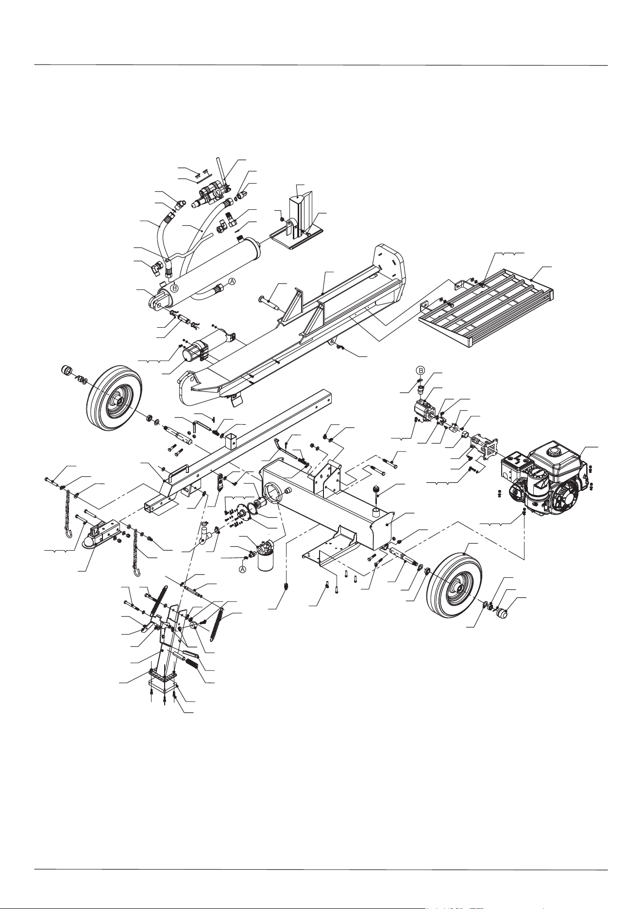
26
DIAGRAMA
22
73
19
52
58
71
56
57
39
44
53
35
33
23
54
42
46
40
25
63
11
63
38
12
18
14
72
20
946370
93
17
16
13
91
88
89
81
85
86
90
87
30
59
75
73
95
79
64
12
63
84
83
80
23
12 63 65
12
49
51
18
61
48
47
63
4568 43
76
7877
37
66
63
67
60
38
54
96
63
9
2
4
45 43 92
5
3
7
18
6
15
18
62
10
18
36
50
8
32
73
7475
21
3431
55
29
27
28
6926
90
31
82
24
41 1

27
LISTA DE COMPONENTES
N.º ref. Pieza n.º Descripción Cant.
1 9121-06010-FH M6x10 Tornillo de sujeción interno - cono hexagonal 1
2 LSP3200-08000-0CG Cilindro 1
3 LSP3200-00002 Tubo de metal 1
4 LSP25-00005-DX Pasador R 2
5 LSP25-00004-DX Pasador del cilindro 1
6 LSP3200-00005 Manguera hidráulica (válvula-filtro externo) 1
7 LSP3200-04000 Conector 2
8 LSP3200-00012 Válvula de control 1
9 LSP3200-03000 Conector de combinación 1
10 LSP3200-00003-DX Rótula de 130° 1
11 LSP25-00006-DX Pasador 1
12 9206-12000-DX M12 Contratuerca de nylon 6
13 LSP3200-02000 Cuña 1
14 9101-14080-DX8.8 M14x80 Perno hexagonal 1
15 LSP3200-00006 Manguera hidráulica (válvula-bomba de engranajes) 1
16 LSP3200-01000-0CR Viga 1
17 LSP3700-00001-DX Pasador de enganche 1
18 9901-19×2.65 Ø19x2.65 Junta tórica 5
19 LSP25-00010-DX Tapón del depósito de aceite 1
20 LSP25-00012-DX Pasador R 1
21 9101-08030-DX8.8 M8x30 Perno hexagonal 4
22 LSP3200-00001-DX Conector de la bomba de engranajes 1
23 9101-12100-DX8.8 M12x100 Perno hexagonal 3
24 LSP35-02006 Bomba de engranajes 13/3.0 1
25 LSP25-13000 Tapón de llenado 1
26 LSP35-02003 Acoplador de la bomba de engranajes 1
27 LSP30A-10004 Acoplador del motor 1
28 LSP30A-10002-DX Camisa del eje del motor 1
29 LSP30A-10001 Base de la bomba de engranajes 1
30 LSP3700-04000 Conjunto de la pata de apoyo delantera 1
31 9306-08000-DX Ø8 Arandela de bloqueo 12
32 LSP30A-10003 Motor 1
33 LSF3000-18000-G Rueda 2
34 9301-08000-DX Ø8 Arandela plana 8
35 LSP25-00020-FH M20x1.5 Tuerca hexagonal ranurada delgada 2
36 LSP3200-00004-DX Conector angular 1
37 LSP30-00007 Filtro de aceite 1

LISTA DE COMPONENTES
28
N.º ref. Pieza n.º Descripción Cant.
38 9404-03030-DX Ø3x30 Chaveta 2
39 LSP25-00009-DX Tapa del eje 2
40 LSP30-00006 Arandela de goma 1
41 LSP25-10008-FH Anillo de retención de alambre de acero para eje 1
42 LSP3700-02000 Depósito del fluido hidráulico 1
43 9301-06000-DX Ø6 Arandela plana 9
44 9101-10045-DX8.8 M10x45 Perno hexagonal 4
45 9101-06020-DX8.8 M6x20 Perno hexagonal 9
46 LSP30-15000 Placa de montaje del filtro 1
47 LSP25-09000 Filtro roscado 1
48 LSP4001-00008-DX Conector 1
49 LSP25-00011-DG Abrazadera 2
50 LSP2700-00005 Plancha 1
51 LSP3200-00011 Tubo de aceite transparente 1
52 9301-20000-DX Ø20 Arandela plana 2
53 LSP3700-00003 Eje de rueda 2
54 LSP25-00003-DX Resorte 2
55 9101-08025-DX8.8 M8x25 Perno hexagonal 4
56 LSP25-14002 Sello de aceite 2
57 L44643 Cojinete de rodillos cónicos 4
58 9101-10055-DX8.8 M10x55 Perno hexagonal 4
59 LSP2501-09000 Soporte de bloqueo de soldadura 1
60 LSP3700--03000-0CR Conjunto de la barra de remolque 1
61 LSP25-11000-DX Cadena 2
62 9110-08010-DX M8x10 Tornillo 2
63 9301-12000-DX Ø12 Arandela plana 14
64 Z103 Acoplador de 2 pulgadas 1
65 9101-12080-DX8.8 M12x80 Perno hexagonal 2
66 LSP25-00015-DX Arandela gruesa 2
67 9101-12090-DX8.8 M12x90 Perno hexagonal 1
68 9306-06000-DX Ø6 Arandela de bloqueo 6
69 LSP25-10009-0CR Chaveta plana de la bomba de engranajes 1
70 9101-12030-DX8.8 M12x30 Perno hexagonal 2
71 9404-04036-DX Ø4x36 Chaveta 2
72 9206-14000-DX M14 Contratuerca de nylon 1
73 9206-10000-DX M10 Contratuerca de nylon 10
74 9306-10000-DX Ø10 Arandela de bloqueo 4

29
LISTA DE COMPONENTES
N.º ref. Pieza n.º Descripción Cant.
75 9301-10000-DX Ø10 Arandela plana 8
76 LSP2501-00011 Correa de conexión 1
77 9302-06000-DX Ø6 Arandela plana grande 1
78 9199-06325-CD Tornillo de cabeza hexagonal con brida ST6.3 × 25 1
79 9304-01500 Ø15 Anillo de seguridad para eje 2
80 LSF3000-00003 El pasador de resorte 1
81 LSF3000-00006 Resorte para pata de soporte 2
82 LSP25-10010 Chaveta plana del motor 1
83 9101-10110-DX8.8 M10x110 Perno hexagonal 1
84 9105-10030-DX M10x30 Tornillo de cabeza redonda hexagonal 1
85 LSF3000-00050 Alfombra de goma 1
86 N560-00019 Manga de la manija 1
87 E050-05002 Cubierta de goma 1
88 LSF3000-00051 Cojín Elástico 1
89 9105-08025-DX M8x25 Tornillo de cabeza redonda hexagonal 4
90 9206-08000-DX M8 Contratuerca de nylon 12
91 LSP30MD-02000 Recipiente manual 1
92 9206-06000-DX M6 Contratuerca de nylon 3
93 LSP3001-06000-0CR Tabla de registro 1
94 9306-12000-DX Ø12 Arandela de bloqueo 2
95 LSF3000-00004 Colgante de primavera 2
96 LSP25-00008-DX Pasador 1

GARANTÍA LIMITADA
Duración de la garantía
YTL International ofrece al comprador original del divisor de leños reemplazo o reparación debido a defectos de materiales y mano de obra hasta 3 años después de la fecha de compra.
La garantía del fabricante del motor cubre al motor durante 2 años. YTL International reemplazará los componentes del sistema hidráulico hasta un año después de la fecha de compra.
Esta garantía no cubre ninguna unidad debido a ensamblaje incorrecto, uso indebido, sobrecarga o uso contrario a nuestras instrucciones, o debido a reparación o alteración por terceros
que no sean representantes autorizados por YTL International Inc.
Exclusiones de la garantía
Esta garantía no cubre defectos cosméticos tales como pintura, etiquetas adhesivas o desgaste de componentes como neumáticos. Esta garantía no cubre fallos o problemas causados
por actos fortuitos o eventos que escapan al control del fabricante.
Exclusión por desgaste normal
El divisor de leños requiere mantenimiento periódico para funcionar correctamente. Esta garantía no cubre reparación cuando el uso normal ha agotado la vida útil de algún componente
o del equipo completo.
Exclusión de instalación, uso y mantenimiento
Esta garantía no cubre piezas o mano de obra del divisor de leños debido a uso indebido, negligencia, accidentes, abuso, sobrecarga, modificación o ensamblaje incorrecto. La garantía
tampoco cubre el mantenimiento normal.
Límites de la exclusión por daños emergentes y la garantía implícita
YTL International desconoce cualquier obligación de cubrir cualquier pérdida de tiempo, uso del producto, transporte o cualquier reclamo incidental o emergente de cualquier persona por
usar este divisor de leños. ESTA GARANTÍA PREVALECERÁ SOBRE CUALQUIER OTRA GARANTÍA, EXPRESA O IMPLÍCITA, INCLUIDAS LAS GARANTÍAS DE COMERCIALIZACIÓN
O APTITUD PARA UN FIN DETERMINADO.
Una unidad de reemplazo estará sujeta a la garantía original. El plazo de garantía de la unidad de reemplazo comenzará en la fecha de compra de la unidad original. Esta garantía le
otorga ciertos derechos legales que podrían cambiar de un estado a otro. Su estado también podría otorgarle otros derechos que no están estipulados en esta garantía.
Product manufactured by: YTL International Inc.
Producto fabricado por: YTL International Inc.
Produit fabriqué par: YTL International Inc.
LICENSEE NAME: YTL International Inc.
LICENSEE ADDRESS: 17517 Fabrica Way Suite H Cerritos, CA 90703
For product, service or warranty information contact us at:
Para obtener información sobre el producto, el mantenimiento
o la garantía, comuníquese con nosotros en:
Pour obtenir de l'information sur les produits, les réparations ou
la garantie, prière de nous contacter au:
U.S. & Canada Only • É.-U. et Canada seulement
www.CRAFTSMAN.com • 888-331-4569
CRAFTSMAN®
is a registered trademark of Stanley Black & Decker, Inc., used under license.
es una marca registrada de Stanley Black & Decker, Inc., utilizada bajo licencia.
est une marque déposée de Stanley Black & Decker, Inc., utilisée sous licence.
