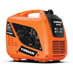
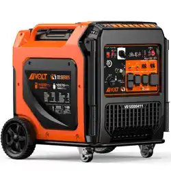
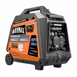
User Manual Inverter Generator
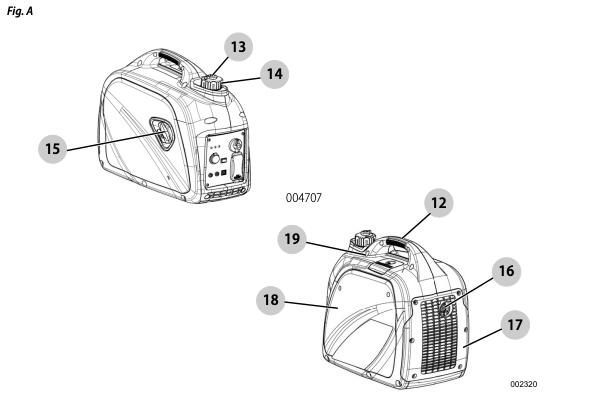
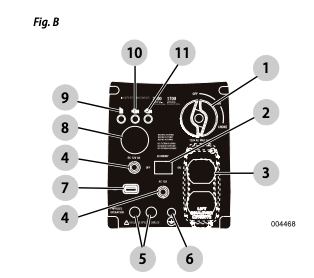
See Fig. A and Fig. B.
Generator Components
- Start Dial (Off/Run/Choke)
- Eco Mode Switch
- 120V, 20A Outlet
- Circuit Protector (if equipped)
- Parallel Ports
- Grounding Locations
- 1.5A, 5VDC USB Port
- DC Outlet (battery charger)
- Low Oil Warning
- Overload Warning
- AC Power Light
- Carrying Handle
- Fuel Tank Vent
- Fuel Cap
- Recoil Starter
- Spark Arrestor
- Muffler Cover
- Service Door
- Spark Plug Cover
Know Your Generator
WARNING: Consult Manual. Read and understand manual completely before using product. Failure to completely understand manual and product could result in death or serious injury. (000100a)
Outlets
120 VAC, Duplex Outlet
See Fig. C. The 120 Volt outlet is overload protected by the 15 Amp push button circuit protector. Each outlet will power 120 Volt AC, single phase, 60 Hz electrical loads requiring up to 1700 watts (1.7 kW).
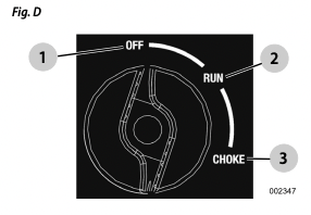
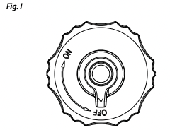
Start Dial (Off/Run/Choke)
This controls the ON/OFF functions, choke and fuel valve operation (Fig. D).
• The OFF position stops the engine and shuts off fuel flow.
• The RUN position  is for normal operation and to gradually reduce the use of the choke.
• The CHOKE position switches the fuel valve on to start the engine.
NOTE: The CHOKE is not required to start a warm engine.
USB Port
The 5 VDC, 1.5 Amp USB outlet allows charging of compatible electronic devices
Eco Mode
The economy switch has 2 modes of operation:
• On: The quietest mode and best when running appliances or equipment that are resistive loads (non-motor starting), (example: TV, video game, light, radio).
• Off: Best when running a both inductive (motor-starting loads) and resistive (non-motor starting loads), especially when these loads are turning on and off (example: RV, air conditioner, hairdryer).
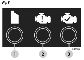
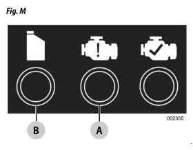
Generator Status Lights
See Fig. E.
• Overload LED (orange): Indicates system overload . During motor starting it is normal for the overload LED to illuminate for a few seconds. If LED stays illuminated and the ready LED turns off, the engine will continue to run without output power. Remove all applied loads and determine if attached devices exceed recommended output power. Check for faulty or shorted connections. To restore electrical output, turn dial OFF to reset. Start engine. If condition was corrected, the orange LED will not illuminate and electrical output will be restored. Loads can be applied once the green LED illuminates. If the orange LED returns, contact an IASD.
• Low Oil Level LED (red): Illuminates when oil level is below safe operating level. Engine shuts down.
• Power LED (green): Indicates output from generator (unless there is a low oil or overload condition).
Circuit Protectors
The AC outlets are protected by an AC circuit protector. The DC outlets are protected by a DC circuit protector. If the generator is overloaded or an external short circuit occurs, the circuit protector will trip. If this occurs, disconnect all electrical loads to determine the cause of the problem before using the generator again. Reduce the load if the circuit protector is tripped.
NOTE: Continuous tripping of the circuit protector may cause damage to generator or equipment. Push the button of the protector to reset the circuit protector.
Add Engine Oil
CAUTION: Engine damage. Verify proper type and quantity of engine oil prior to starting engine. Failure to do so could result in engine damage. (000135)
NOTE: The generator is shipped without oil in the engine. Add oil slowly and verify oil level often during filling process to ensure overfilling does not occur.
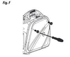
See Fig. F, Fig. G and Fig. H.
- 1. Place generator on a level surface.
- 2. Remove screws and side cover.
- 3. Clean area around oil fill and oil drain plug.
- 4. Remove oil fill cap and wipe dipstick clean.
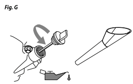
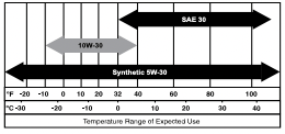
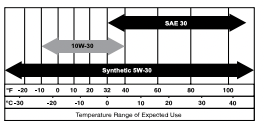
- 5. Insert funnel into oil fill opening. Add recommended engine oil as necessary. Climate determines proper engine oil viscosity. See chart to select correct viscosity.
NOTE: Use petroleum based oil (supplied) for engine breakin before using synthetic oil.
- 6. To check oil level, remove funnel and insert dipstick into oil filler neck.
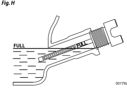
- 7. Remove dipstick and verify oil level is within safe operating range.
NOTE: Verify oil level often during filling process to ensure overfilling does not occur.
- 8. Install oil fill cap/dipstick and hand-tighten.
- 9. Replace side cover and screws.
Fuel
DANGER: Explosion and Fire. Fuel and vapors are extremely flammable and explosive. Add fuel in a well ventilated area. Keep fire and spark away. Failure to do so will result in death or serious injury. (000105)
DANGER: Explosion and Fire. Do not overfill fuel tank. Fill to 1/2 inch from top of tank to allow for fuel expansion. Overfilling may cause fuel to spill onto engine causing fire or explosion which will result in death or serious injury. (000166b)
See Fig. I and Fig. J.
Fuel requirements are as follows:
• Clean, fresh, unleaded gasoline.
• Minimum rating of 87 octane/87 AKI (91 RON).
• Up to 10% ethanol (gasohol) is acceptable.
• DO NOT use E85.
• DO NOT use a gas oil mix.
• DO NOT modify engine to run on alternate fuels. Stabilize fuel prior to storage.
- 1. Verify unit is OFF and cooled entirely prior to fueling.
- 2. Place unit on level ground in a well ventilated area.
WARNING: Explosion and Fire. Verify fuel cap vent is set to ON for operation, and OFF for transportation and storage. Failure to do so could result in poor unit performance, death or serious injury. (000362)
- 3. Clean area around fuel cap and turn vent on fuel cap to ON.
- 4. Turn cap slowly to remove.
- 5. Slowly add recommended fuel. Do not overfill.
NOTE: Fill to red insert inside filler neck.
- 6. Install fuel cap.
- 7. Turn vent on fuel cap to OFF for transportation and storage to avoid fuel spills.
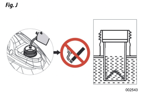
NOTE: Allow spilled fuel to evaporate before starting unit.
OPERATION
Operation and Use Questions
Call Customer Service at 1-888-331-4569 with questions or concerns about equipment operation and maintenance.
Before Starting Engine
- 1. Verify engine oil level is correct.
- 2. Verify fuel level is correct.
- 3. Verify unit is secure on level ground, with proper clearance and is in a well ventilated area.
Prepare Generator for Use
DANGER: Asphyxiation. Running engines produce carbon monoxide, a colorless, odorless, poisonous gas. Carbon monoxide, if not avoided, will result in death or serious injury. (000103)
DANGER: Asphyxiation. The exhaust system must be properly maintained. Do not alter or modify the exhaust system as to render it unsafe or make it noncompliant with local codes and/or standards. Failure to do so will result in death or serious injury. (000179b)
WARNING: Risk of fire. Do not use generator without spark arrestor installed. Failure to do so could result in death or serious injury. (000118a)
WARNING: Asphyxiation. Always use a battery operated carbon monoxide alarm indoors and installed according to the manufacturer’s instructions. Failure to do so could result in death or serious injury. (000178a)
WARNING: Risk of Fire. Hot surfaces could ignite combustibles, resulting in fire. Fire could result in death or serious injury. (000110)
WARNING: Hot surfaces. When operating machine, do not touch hot surfaces. Keep machine away from combustibles during use. Hot surfaces could result in severe burns or fire. (000108)
CAUTION: Equipment and property damage. Disconnect electrical loads prior to starting or stopping unit. Failure to do so could result in equipment and property damage. (000136)
Grounding the Generator When In Use
The generator is equipped with an equipment ground connecting the generator frame and the ground terminals on the AC output outlets (see NEC 250.34 . This allows the generator to be used as a portable without grounding the frame of the generator as specified in NEC 250.34 (Fig. K).
• Neutral Floating
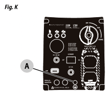
The generator (stator winding) is isolated from the frame and from the AC outlet ground pin. Electrical devices that require a grounded outlet pin connection will not function if the outlet ground pin is not functional.
Know Generator Limits
Overloading a generator can result in damage to the generator and connected electrical devices. Observe the following to prevent overload:
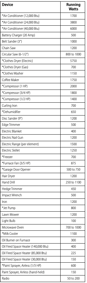
• Add up the total wattage of all electrical devices to be connected at one time. This total should NOT be greater than the generator's wattage capacity.
• The rated wattage of lights can be taken from light bulbs. The rated wattage of tools, appliances, and motors can be found on a data label or decal affixed to the device.
• If the appliance, tool, or motor does not give wattage, multiply volts times ampere rating to determine watts (volts x amps = watts).
• Some electric motors, such as induction types, require about three times more watts of power for starting than for running. This surge of power lasts only a few seconds when starting such motors. Make sure to allow for high starting wattage when selecting electrical devices to connect to the generator:
- 1. Figure the watts needed to start the largest motor.
- 2. Add to that figure the running watts of all other connected loads.
Wattage Reference Guide is provided to assist in determining how many items the generator can operate at one time.
NOTE: All figures are approximate. See data label on appliance for wattage requirements.
Wattage Reference Guide
Transporting/Tipping of the Unit
Do not store or transport the unit at an angle greater than 15 degrees.
Starting Pull Start Engines
WARNING: Recoil Hazard. Recoil could retract unexpectedly. Kickback could result in death or serious injury. (000183)
CAUTION: Equipment and property damage. Disconnect electrical loads prior to starting or stopping unit. Failure to do so could result in equipment and property damage. (000136)
See Fig. L and Fig. M.
- 1. Turn fuel cap vent ON.
- 2. Rotate the Off/Run/Choke dial to CHOKE .
- 3. Switch Economy switch to OFF.
- 4. Firmly grasp recoil handle and pull slowly until increased resistance is felt. Pull rapidly up and away.
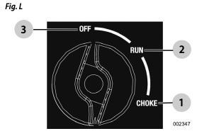
- 5. When engine starts, rotate Off/Run/Choke dial to RUN . Choke operation is reduced as Off/Run/ Choke dial is rotated towards RUN.
NOTE: If engine fires, but does not continue to run, rotate the Off/Run/Choke dial to OFF and repeat starting instructions.
IMPORTANT: Do not overload generator or individual panel outlets. If an overload occurs, the overload LED A will illuminate and AC output ceases. To correct, see Generator Status Lights. Read Know Generator Limits carefully.
Generator Shut Down
CAUTION: Equipment and property damage. Disconnect electrical loads prior to starting or stopping unit. Failure to do so could result in equipment and property damage. (000136)
- 1. Shut off all loads and unplug electrical loads from generator panel outlets.
- 2. Let engine run at no-load for several minutes to stabilize internal temperatures of engine and generator.
- 3. Rotate Off/Run/Choke dial to OFF .
- 4. Turn fuel cap OFF.
Restarting Hot Engines
CAUTION: Equipment and property damage. Disconnect electrical loads prior to starting or stopping unit. Failure to do so could result in equipment and property damage. (000136) See Fig. L.
- 1. Turn Off/Run/Choke dial from STOP to RUN. This will open the fuel valve and permit starting.
- 2. Firmly grasp recoil handle and pull slowly until increased resistance is felt. Pull rapidly up and away.
Low Oil Level Shutdown System
The engine is equipped with a low oil level sensor that shuts down the engine automatically when the oil level drops below a specified level to prevent engine damage B . The engine will not run until the oil has been filled to the proper level (Fig. M). If the engine shuts down and there is sufficient fuel, check engine oil level.
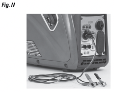
Charging a 12 VDC Battery
WARNING: Explosion. Batteries emit explosive gases while charging. Keep fire and spark away. Wear protective gear when working with batteries. Failure to do so could result death or serious injury. (000137a)
WARNING: Risk of burns. Batteries contain sulfuric acid and can cause severe chemical burns. Wear protective gear when working with batteries. Failure to do so could result death or serious injury. (000138a)
NOTE: A battery may lose some of its charge when not in use for prolonged periods of time. The DC charging output is not regulated. The circuit protector does not prevent over charging a battery. Battery charging should be done in a dry location (Fig. N).
- 1. Start generator and turn Economy switch OFF.
- 2. Plug Battery Charging Cable into Battery Charger Output jack, located on the control panel.
- 3. Connect positive (+) battery clamp (red wire) to battery FIRST.
- 4. Connect negative (-) battery clamp (black wire) to battery SECOND.
NOTE: This outlet can not recharge 6-volt batteries and can not be used to crank an engine having a discharged battery
WARNING: Environmental Hazard. Aways recycle batteries at an official recycling center in accordance with all local laws and regulations. Failure to do so could result in environmental damage, death or serious injury. (000228)
Parallel Operation
For output power up to 3230W, two inverters can operate in parallel using Parallel Kit (optional). See the Parallel Kit Operator’s Manual or contact Customer Service at 1- 888-331-4569.
NOTE: All connections to the parallel kit should be made while both inverters are turned off and all loads disconnected.
- 1. Make sure the Eco Mode Switch is in the same position on both generators.
- 2. Make appropriate parallel connections to the outlets on each inverter as outlined in the owner’s manual supplied with the kit.
NOTE: Do not disconnect any parallel kit connections once the units are running.
- 3. Start both units per starting instructions. Once the green output indicator illuminates, devices can be connected and turned on using the parallel kit outlet.
- 4. Follow Generator Shut Down instructions.
NOTE: For inverters, load applied to the parallel kit is not to exceed 3230 watts due to a 5% power loss when paralleling. See manual.
NOTE: Only use approved parallel kit.
MAINTENANCE AND TROUBLESHOOTING
Regular maintenance will improve performance and extend engine/equipment life. Contact Customer Service at 1-888-331-4569, or CRAFTSMAN to find a dealer for maintenance work to be performed. Regular maintenance, replacement or repair of the emissions control devices and systems may be performed by any repair shop or person of the owner’s choosing. However, to obtain emissions control warranty service free of charge, the work must be performed by a CRAFTSMAN service dealer. See the emissions warranty.
NOTE: Call 1-888-331-4569 with questions about component replacement.
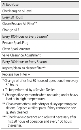
Maintenance Schedule
Follow maintenance schedule intervals, whichever occurs first according to use.
NOTE: Adverse conditions will require more frequent service.
NOTE: All required service and adjustments should be each season as detailed in the following chart.
Preventive Maintenance
Dirt or debris can cause improper operation and equipment damage. Clean generator daily or before each use. Keep area around and behind muffler free from combustible debris. Inspect all cooling air openings on generator.
WARNING: Personal injury. Do not insert any object through the air cooling slots. Generator can start at any time and could result in death, serious injury, and unit damage. (000142a)
• Use a damp cloth to wipe exterior surfaces clean.
• Use a soft bristle brush to loosen caked on dirt, oil, etc.
• Use a vacuum to pick up loose dirt and debris.
• Low pressure air (not to exceed 25 psi) may be used to blow away dirt. Inspect cooling air slots and openings on generator. These openings must be kept clean and unobstructed.
NOTE: DO NOT use a garden hose to clean generator. Water can enter engine fuel system and cause problems. If water enters generator through cooling air slots, some water will be retained in voids and crevices of rotor and stator winding insulation. Water and dirt buildup on generator internal windings will decrease insulation resistance of windings.
Engine Maintenance
WARNING: Personal injury. Do not insert any object through the air cooling slots. Generator can start at any time and could result in death, serious injury, and unit damage. (000142a)
WARNING: Accidental start-up. Disconnect spark plug wires when working on unit. Failure to do so could result in death or serious injury. (000141)
Engine Oil Recommendations
To maintain the product warranty, the engine oil should be serviced in accordance with the recommendations of this manual. For your convenience, maintenance kits designed and intended for use on this product are available from the manufacturer that include engine oil, oil filter, air filter, spark plug(s), a shop towel and funnel. These kits can be obtained by contacting Customer Service at 1-888-331-4569.
Inspect Engine Oil Level
WARNING: Risk of burns. Allow engine to cool before draining oil or coolant. Failure to do so could result in death or serious injury. (000139) See Fig. O and Fig. P. Inspect engine oil level prior to each use, or every 8 hours of operation.
- 1. Place generator on a level surface.
- 2. Clean area around oil fill, and oil drain plug.
- 3. Remove oil fill cap and wipe dipstick clean.
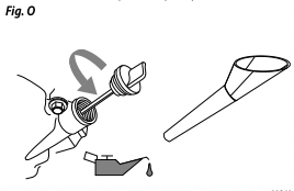
- 4. To check oil level, insert dipstick into oil filler neck without screwing it in.
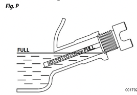
- 5. Remove dipstick and verify oil level is within safe operating range.
- 6. Add recommended engine oil as necessary.
NOTE: Verify oil level often during filling process to ensure overfilling does not occur.
- 7. Replace oil fill cap and hand-tighten.
NOTE: Some units have more than one oil fill location. It is only necessary to use one oil fill point.
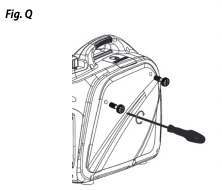
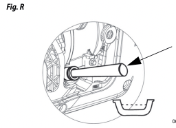
Change Engine Oil
WARNING: Accidental start-up. Disconnect spark plug wires when working on unit. Failure to do so could result in death or serious injury. (000141) When using generator under extreme, dirty, dusty conditions, or in extremely hot weather, change oil more frequently (Fig. Q and Fig. R).
NOTE: Don’t pollute. Conserve resources. Return used oil to collection centers. Change oil while engine is still warm from running, as follows:
- 1. Place generator on a level surface.
- 2. Remove screws and side cover.
- 3. Disconnect the spark plug wire from the spark plug and place the wire where it cannot contact spark plug.
- 4. Clean area around oil fill and oil drain plug.
- 5. Remove oil fill cap and wipe dipstick clean.
- 6. Tip unit and drain oil completely into a suitable container.
- 7. Once oil is sufficiently drained from unit, tip unit back to a level position.
- 8. Insert funnel into oil fill opening. Add recommended engine oil as necessary
- 9. To check oil level, remove funnel and insert dipstick into oil filler neck without screwing it in.
- 10. Remove dipstick and verify oil level is within safe operating range.
NOTE: Verify oil level often during filling process to ensure overfilling does not occur.
- 11. Replace oil fill cap and hand-tighten.
- 12. Wipe up any spilled oil.
- 13. Replace side cover and screws.
- 14. Properly dispose of oil in accordance with all applicable regulations.
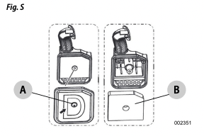
Air Filter
Engine will not run properly and may be damaged if run with a dirty air filter. Service air filter more frequently in dirty or dusty conditions (Fig. S). To service air filter:
- 1. Remove screws and side cover.
- 2. Unscrew bolt A and remove air filter cover.
- 3. Wash filter B in soapy water. Squeeze dry in clean cloth (DO NOT TWIST).
- 4. Clean air filter cover before installation.
- 5. Replace side cover and screws.
NOTE: To order a new air filter, contact the nearest authorized service center at 1-888-436-3722.
Service Spark Plug
To service spark plug (Fig. T):
- 1. Remove spark plug cover.
- 2. Clean area around spark plug.
- 3. Remove and inspect spark plug.
- 4. Inspect electrode gap with wire feeler gauge and reset spark plug gap to 0.6 - 0.7mm (0.024 - 0.028 in).
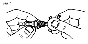
NOTE: Replace spark plug if electrodes are pitted, burned or porcelain is cracked. Use ONLY recommended replacement plug. See Product Specifications.
- 5. Install spark plug finger tight, and tighten an additional 3/8 to 1/2 turn using spark plug wrench.
Inspect Muffler and Spark Arrester
NOTE: It is a violation of California Public Resource Code, Section 4442, to use or operate the engine on any forestcovered, brush-covered, or grass-covered land unless the exhaust system is equipped with a spark arrester, as defined in Section 4442, maintained in effective working order. Other states or federal jurisdictions may have similar laws. Contact original equipment manufacturer, retailer, or dealer to obtain a spark arrester designed for exhaust system installed on this engine.
NOTE: Use ONLY original equipment replacement parts. Inspect muffler for cracks, corrosion, or other damage. Remove spark arrester, if equipped, inspect for damage or carbon blockage. Replace parts as required.
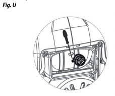
Inspect Spark Arrester Screen (Fig. U)
WARNING: Hot surfaces. When operating machine, do not touch hot surfaces. Keep machine away from combustibles during use. Hot surfaces could result in severe burns or fire. (000108) Clean Spark Arrestor Screen (Fig. U) The engine exhaust muffler has a spark arrestor screen. Inspect and clean the screen every 100 hours of operation or every season, whichever comes first. To service spark arrestor:
- 1. Remove the clamp to remove retainer.
- 2. Slide spark arrestor screens out from the muffler outlet tube.
- 3. Inspect screens and replace if torn, perforated or otherwise damaged. Do NOT use a defective screen. If screen is not damaged, clean with a commercial solvent.
- 4. Replace the screens, and retainer, and secure with clamp.
Valve Clearance
If uncomfortable about doing this procedure, or the proper tools are not available, take generator to the nearest service center to have valve clearance adjusted. Check valve clearance after the first fifty-hours of operation. Adjust as necessary.
• Intake — 0.10 ± 0.02mm (cold), (0.004" ± 0.001" inches)
• Exhaust — 0.10 ± 0.02mm (cold) (0.004" ± 0.001" inches)
Storage
General
DANGER: Explosion and Fire. Fuel and vapors are extremely flammable and explosive. Store fuel in a well ventilated area. Keep fire and spark away. Failure to do so will result in death or serious injury. (000143)
WARNING: Risk of Fire. Verify machine has properly cooled before installing cover and storing machine. Hot surfaces could result in fire. (000109)
It is recommended to start and run the generator for 30 minutes, every 30 days. If this is not possible, refer to the following list to prepare unit for storage.
• DO NOT place a storage cover on a hot generator. Allow unit to cool to room temperature before storage.
• DO NOT store fuel from one season to another unless properly treated.
• Replace fuel container if rust is present. Rust in fuel will cause fuel system problems.
• Cover unit with a suitable protective, moisture resistant cover.
• Store unit in a clean, dry area.
• Always store generator and fuel away from heat and ignition sources.
Prepare Fuel System/Engine for Storage
Fuel stored over 30 days can go bad and damage fuel system components. Keep fuel fresh, use fuel stabilizer. If fuel stabilizer is added to fuel system, prepare and run engine for long term storage. Run engine for 10-15 minutes to circulate stabilizer throughout fuel system. Adequately prepared fuel can be stored up to 24 months.
NOTE: If fuel has not been treated with fuel stabilizer, it must be drained into an approved container. Run engine until it stops from lack of fuel. Use of fuel stabilizer in fuel storage container is recommended to keep fuel fresh.
- 1. Change engine oil.
- 2. Remove spark plug.
- 3. Pour tablespoon (5-10cc) of clean engine oil or spray a suitable fogging agent into cylinder.
- WARNING: Vision Loss. Eye protection is required to avoid spray from spark plug hole when cranking engine. Failure to do so could result in vision loss. (000181)
- 4. Pull starter recoil several times to distribute oil in cylinder.
- 5. Install spark plug.
- 6. Pull recoil slowly until resistance is felt. This will close valves so moisture cannot enter engine cylinder. Gently release recoil.
Change Oil
Change engine oil before storage. See, Change Engine Oil.
Troubleshooting
Engine won't start.
1. Dial turned off.
2. Out of fuel.
3. Defective spark plug.
4. Plugged fuel filter.
- 4. Replace fuel and fuel filter.
5. Defective or stuck Dial assembly.
- 5. Contact Customer Service at 1-888- 331-4569.
6. Incorrect engine oil level.
- 6. Check/fill engine oil.
7. Defective ignition coil.
- 7. Contact Customer Service at 1-888- 331-4569.
8. Fuel cap vent OFF.
- 8. Turn fuel cap vent ON.
9. Carb is flooded.
10. Throttle plate closed.
- 10. Open throttle plate (push toward back of unit).
Engine starts, then shuts down.
1. Out of fuel.
2. Incorrect engine oil level.
- 2. Check engine oil level.
3. Contaminated fuel.
- 3. Contact Customer Service at 1-888- 331-4569.
4. Defective low oil level switch.
- 4. Contact Customer Service at 1-888- 331-4569.
5. Fuel cap vent OFF.
- 5. Turn fuel cap vent ON.
Engine will not start; or starts and runs rough.*
1. Choke is stuck or left on.
2. Dirty or clogged air filter.
- 2. Clean or replace air filter.
3. Defective or dirty spark plug.
4. Dirty fuel filter.
- 4. Replace fuel and fuel filter.
5. Dirty or gummed up carburettor.
6. Unit not warmed up.
- 6. Gradually adjust Dial and reduce choke until engine runs smoothly in RUN position.
7. Fuel cap vent OFF.
- 7. Turn fuel cap vent ON.
8. Spark arrestor clogged.
No AC output.
1. Generator is overloaded.
- 1. Disconnect all loads. Shut down generator to reset module. Reduce loads, restart generator.
2. Inverter module is overheated.
- 2. Verify service door is ON. Let cool 15 minutes by running engine without AC output. Press and hold Reset button on control panel, restart generator.
3. Short circuit in electrical device.
- 3. Verify condition of extension cords and items being powered. Press and hold Reset button on control panel.
4. Defective inverter assembly
- 4. Contact Customer Service at 1-888- 331-4569.
Fuel leaks from drain hoses.
1. Carburetor drain in bowl is not closed.
- 1. Turn valve clockwise to close.
* Engine speed increases and decreases — This is normal as generator starts up and loads vary.