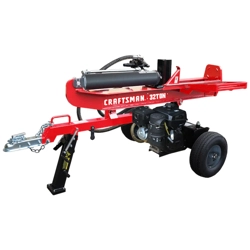

Operator's Manual
CRRF[SM ®
675 Series
LOG SPLITTER
Model No. 247.77640
CAUTION: Before using
this product, read this
manual and follow all
safety rules and operating
instructions.
o SAFETY
ASSEMBLY
OPERATION
MAINTENANCE
PARTS LIST
Espa_ol
Sears Brands Management Corporation, Hoffman Estates, IL 60179, U.S.A.
Visit our website: www.craftsman.com FORMNO.769-05144A
6/11/2010
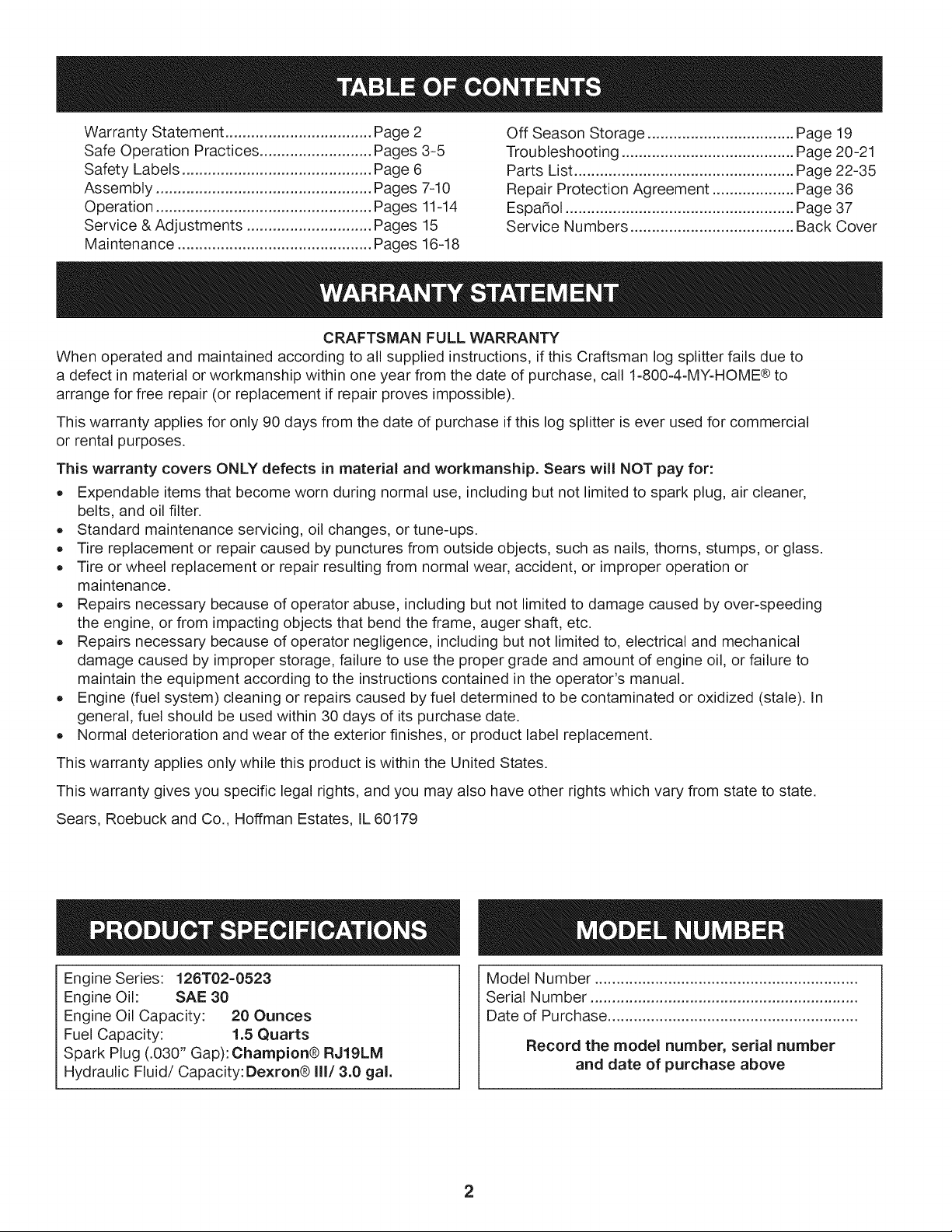
WarrantyStatement..................................Pac
SafeOperationPractices..........................Pac
SafetyLabels............................................Pac
Assembly..................................................Pac
Operation..................................................Pac
Service&Adjustments.............................Pac
Maintenance.............................................Pac
e2
es3-5
e6
es7-10
es11-14
es15
es16-18
OffSeasonStorage..................................Page19
Troubleshooting........................................Page20-21
PartsList...................................................Page22-35
RepairProtectionAgreement...................Page36
Espa_ol.....................................................Page37
ServiceNumbers......................................BackCover
CRAFTSMANFULLWARRANTY
Whenoperatedandmaintainedaccordingtoallsuppliedinstructions,ifthisCraftsmanlogsplitterfailsdueto
adefectinmaterialorworkmanshipwithinoneyearfromthedateof purchase,call1-800-4-MY-HOME®to
arrangeforfreerepair(orreplacementif repairprovesimpossible).
Thiswarrantyappliesforonly90daysfromthedateof purchaseifthislogsplitteriseverusedforcommercial
orrentalpurposes.
This warranty covers ONLY defects in material and workmanship. Sears will NOT pay for:
• Expendable items that become worn during normal use, including but not limited to spark plug, air cleaner,
belts, and oil filter.
Standard maintenance servicing, oil changes, or tune-ups.
Tire replacement or repair caused by punctures from outside objects, such as nails, thorns, stumps, or glass.
Tire or wheel replacement or repair resulting from normal wear, accident, or improper operation or
maintenance.
Repairs necessary because of operator abuse, including but not limited to damage caused by over-speeding
the engine, or from impacting objects that bend the frame, auger shaft, etc.
Repairs necessary because of operator negligence, including but not limited to, electrical and mechanical
damage caused by improper storage, failure to use the proper grade and amount of engine oil, or failure to
maintain the equipment according to the instructions contained in the operator's manual.
Engine (fuel system) cleaning or repairs caused by fuel determined to be contaminated or oxidized (stale). In
general, fuel should be used within 30 days of its purchase date.
Normal deterioration and wear of the exterior finishes, or product label replacement.
This warranty applies only while this product is within the United States.
This warranty gives you specific legal rights, and you may also have other rights which vary from state to state.
Sears, Roebuck and Co., Hoffman Estates, IL 60179
Engine Series: 126T02-0523
Engine Oil: SAE 30
Engine Oil Capacity: 20 Ounces
Fuel Capacity: 1.5 Quarts
Spark Plug (.030" Gap): Champion® RJ19LM
Hydraulic Fluid/Capacity: Dexron® III/3.0 gal.
Model Number .............................................................
Serial Number ..............................................................
Date of Purchase ..........................................................
Record the model number, serial number
and date of purchase above
2
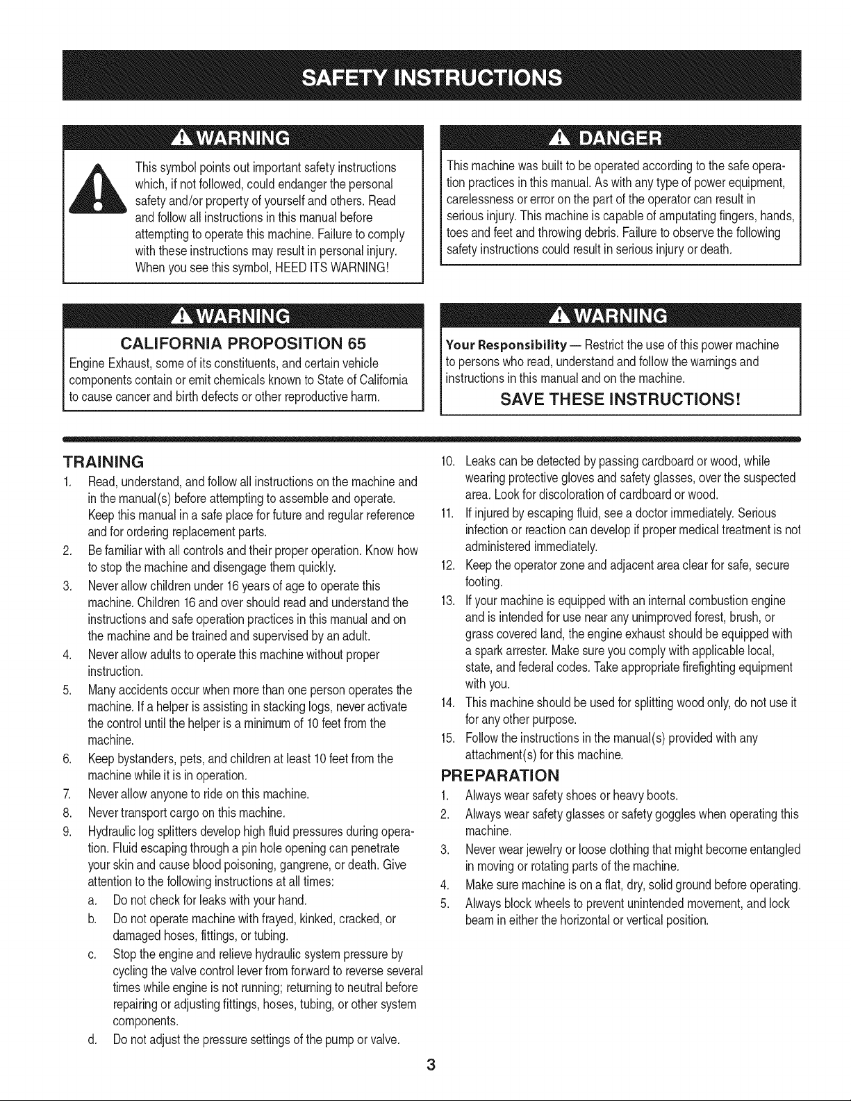
4_ Thissymbolpointsout importantsafetyinstructions
which,if not followed,could endangerthe personal
safetyand/or propertyof yourselfandothers.Read
andfollowall instructionsin thismanualbefore
attemptingto operatethismachine.Failureto comply
withtheseinstructionsmay resultin personalinjury.
Whenyousee this symbol,HEEDITSWARNING!
Thismachinewasbuilt to beoperatedaccordingto the safeopera-
tion practicesin thismanual.As with any typeof powerequipment,
carelessnessor error on the part of the operatorcan resultin
seriousinjury.Thismachineis capableof amputatingfingers,hands,
toesandfeetandthrowingdebris.Failureto observethe following
safetyinstructionscouldresultin seriousinjuryordeath.
CALIFORNIA PROPOSITION 65
EngineExhaust,someof itsconstituents,andcertainvehicle
componentscontainoremitchemicalsknownto Stateof California
to cause cancerand birthdefects or other reproductiveharm.
Your Responsibility-- Restrictthe use of this powermachine
to personswho read,understandandfollowthewarningsand
instructionsin this manualand on the machine.
SAVE THESE INSTRUCTIONS!
TRAINING
1. Read,understand,andfollowall instructionson the machineand
in themanual(s)beforeattemptingto assembleandoperate.
Keepthis manualina safeplacefor futureand regularreference
andfor orderingreplacementparts.
2. Be familiarwith all controlsand their properoperation.Knowhow
to stop the machineanddisengagethemquickly.
3. Neverallowchildrenunder16yearsof age to operatethis
machine.Children16andovershouldreadandunderstandthe
instructionsand safe operationpracticesin thismanualandon
the machineand be trainedand supervisedby an adult.
4. Neverallowadultsto operatethis machinewithoutproper
instruction.
5. Manyaccidentsoccurwhen morethan onepersonoperatesthe
machine.If a helperis assistingin stackinglogs,neveractivate
the controluntilthe helperis a minimumof 10feet from the
machine.
6. Keepbystanders,pets,andchildrenat least10feetfromthe
machinewhile it is in operation.
7. Neverallowanyoneto ride on thismachine.
8. Nevertransportcargoonthis machine.
9. Hydrauliclogsplittersdevelophigh fluidpressuresduringopera-
tion.Fluidescapingthrougha pinholeopeningcan penetrate
yourskinandcausebloodpoisoning,gangrene,or death.Give
attentionto the followinginstructionsat all times:
a. Do notcheckfor leaks with yourhand.
b. Do notoperatemachinewithfrayed,kinked,cracked,or
damagedhoses,fittings,ortubing.
c. Stopthe engineand relievehydraulicsystempressureby
cyclingthe valvecontrolleverfrom forwardto reverseseveral
timeswhileengineis not running;returningto neutralbefore
repairingor adjustingfittings,hoses,tubing,or other system
components.
d. Do notadjustthe pressuresettingsof the pumporvalve.
10. Leakscanbe detectedby passingcardboardor wood, while
wearingprotectiveglovesand safetyglasses,overthe suspected
area. Lookfor discolorationof cardboardorwood.
11. If injuredby escapingfluid,see a doctorimmediately.Serious
infectionor reactioncandevelopif propermedicaltreatmentis not
administeredimmediately.
12. Keeptheoperatorzoneandadjacentareaclearfor safe,secure
footing.
13. If your machineis equippedwith an internalcombustionengine
and is intendedfor usenearanyunimprovedforest,brush,or
grasscoveredland,the engineexhaustshouldbeequippedwith
a sparkarrestor.Makesureyoucomplywith applicablelocal,
state,andfederalcodes.Takeappropriatefirefightingequipment
withyou.
14. This machineshouldbe usedfor splittingwoodonly,do notuse it
for anyother purpose.
15. Followthe instructionsin the manual(s)providedwith any
attachment(s)for this machine.
PREPARATION
1. Alwayswear safetyshoesor heavyboots.
2. Alwayswear safetyglassesor safetygoggleswhenoperatingthis
machine.
3. Neverwearjewelryor looseclothingthatmightbecomeentangled
inmovingor rotatingparts of the machine.
4. Makesuremachineis ona flat,dry,solid groundbeforeoperating.
5. Alwaysblockwheelsto preventunintendedmovement,andlock
beamin eitherthe horizontalorverticalposition.
3
.
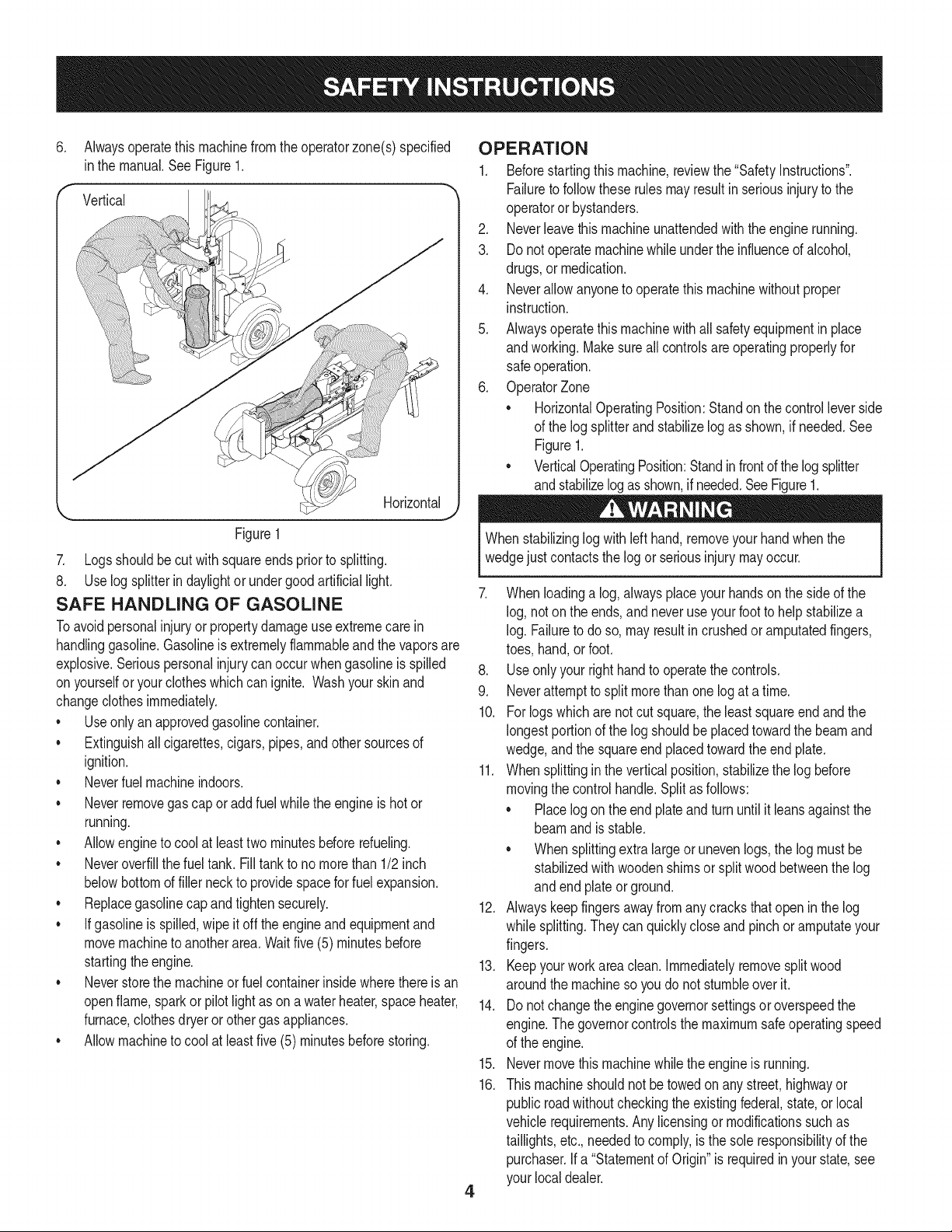
Alwaysoperatethismachinefromtheoperatorzone(s) specified
inthe manual.SeeFigure1.
Vertical
Figure1
7. Logsshouldbe cut withsquareendsprior to splitting.
8. Use log splitterin daylightor undergoodartificiallight.
SAFE HANDLING OF GASOLINE
Toavoidpersonalinjuryor propertydamageuseextremecare in
handlinggasoline.Gasolineis extremelyflammableandthe vaporsare
explosive.Seriouspersonalinjurycan occurwhengasolineis spilled
onyourselfor yourclotheswhichcan ignite. Washyour skin and
changeclothesimmediately.
• Useonlyan approvedgasolinecontainer.
• Extinguishallcigarettes,cigars,pipes,and othersourcesof
ignition.
• Neverfuel machineindoors.
• Neverremovegas capor addfuel whilethe engineis hot or
running.
• Allowengineto coolat leasttwo minutesbeforerefueling.
• Neveroverfillthe fueltank. Filltank to no morethan 1/2inch
belowbottomof filler neckto providespacefor fuel expansion.
• Replacegasolinecapand tighten securely.
• Ifgasolineis spilled,wipe it off theengineandequipmentand
movemachineto anotherarea.Waitfive (5)minutesbefore
startingtheengine.
• Neverstorethe machineorfuel containerinsidewherethereis an
openflame,sparkor pilotlightas on awaterheater,space heater,
furnace,clothesdryer or othergas appliances.
• Allowmachineto cool at leastfive(5) minutesbeforestoring.
OPERATION
1. Beforestartingthis machine,reviewthe "SafetyInstructions".
Failureto followtheserulesmayresultin seriousinjuryto the
operatoror bystanders.
2. Neverleavethis machineunattendedwith the enginerunning.
3. Donot operatemachinewhile underthe influenceof alcohol,
drugs,ormedication.
4. Neverallowanyoneto operatethis machinewithoutproper
instruction.
5. Alwaysoperatethismachinewithall safetyequipmentin place
andworking.Makesureall controlsareoperatingproperlyfor
safeoperation.
6. OperatorZone
• HorizontalOperatingPosition:Standon thecontrolleverside
of the log splitterand stabilizelogas shown,if needed.See
Figure1.
• VerticalOperatingPosition:Standin frontof thelogsplitter
andstabilizelog as shown,if needed.SeeFigure1.
Whenstabilizinglog withlefthand,removeyour handwhenthe
wedgejust contactsthe logor seriousinjurymayoccur.
4
7. Whenloadinga log, alwaysplaceyourhandsonthe sideof the
log, noton the ends,and neveruseyour footto help stabilizea
log. Failureto do so,mayresultin crushedor amputatedfingers,
toes, hand,or foot.
8. Useonly yourrighthandto operatethe controls.
9. Neverattemptto split morethan one log at a time.
10. Forlogswhich are not cutsquare,the leastsquareendandthe
longestportionof the log shouldbe placedtowardthe beamand
wedge,andthe squareend placedtowardthe end plate.
11. Whensplittingin the verticalposition,stabilizethe log before
movingthe controlhandle.Splitas follows:
• Placelog on the end plateand turn untilit leansagainstthe
beamand is stable.
• Whensplittingextralargeor unevenlogs,the log mustbe
stabilizedwith woodenshimsor splitwoodbetweenthe log
andend plateorground.
12. Alwayskeepfingersawayfromany cracksthat open in thelog
while splitting.They canquicklycloseandpinchor amputateyour
fingers.
13. Keepyourworkarea clean. Immediatelyremovesplitwood
aroundthe machineso youdo notstumbleover it.
14. Donot changethe enginegovernorsettingsor overspeedthe
engine.The governorcontrolsthe maximumsafe operatingspeed
of the engine.
15. Nevermove this machinewhilethe engineis running.
16. This machineshouldnotbe towedonany street,highwayor
public roadwithoutcheckingtheexistingfederal,state,orlocal
vehiclerequirements.Any licensingor modificationssuchas
taillights,etc.,neededto comply,is the sole responsibilityof the
purchaser.If a "Statementof Origin"is requiredin your state,see
your localdealer.
17.Donottowmachineover45mph.
18.SeeTransportingtheLogSplittersectioninthismanualforproper
towinginstructionsonceallfederal,local,orstaterequirements
aremet.
MAINTENANCE AND STORAGE
1. Stopthe engine,disconnectthe sparkplugandgroundit against
the enginebeforecleaning,orinspectingthe machine.
2. Stopthe engineandrelievehydraulicsystempressureby cycling
the valvecontrolleverfrom forwardto reverseseveraltimeswhile
engineis not running;returningto neutralbeforerepairingor
adjustingfittings,hoses,tubing,or othersystemcomponents.
3. Topreventfires, cleandebrisand chaff fromthe engineand
mufflerareas. If the engineis equippedwitha sparkarrester
muffler,cleanand inspectit regularlyaccordingto manufacturers
instructions.Replaceif damaged.
4. Periodicallycheckthat all nutsandbolts,hoseclamps,and
hydraulicfittingsaretightto besureequipmentis insafeworking
condition.
5. Checkall safetyguardsand shieldsto be suretheyarein the
properposition.Neveroperatewithsafetyguards,shields,or
otherprotectivefeaturesremoved.
6. Thepressurereliefvalveis presetat thefactory.Donot adjustthe
valve.
7. Neverattemptto movethismachineoverhillyor uneventerrain
withouta towvehicleor adequatehelp.
8. Foryour safety,replaceall damagedor wornpartsimmediately
withoriginalequipmentmanufacturer's(O.E.M) parts only.Use of
partswhichdo notmeetthe originalequipmentspecificationsmay
leadto improperperformanceand compromisesafety!
9. Do notalter this machinein any manner,alterationssuchas
attachinga ropeorextensionto the controlhandle,or addingto
the widthor heightof the wedgemay resultin personalinjury.
10. Accordingto the ConsumerProductsSafetyCommission(CPSC)
andthe U.S.EnvironmentalProtectionAgency(EPA),this product
hasan Average UsefulLifeof seven(7)years,or 130hoursof
operation.At the endof theAverage UsefulLifehavethe machine
inspectedannuallybyan authorizedservicedealerto ensurethat
allmechanicaland safetysystemsare workingproperlyand not
wornexcessively.Failureto do so can resultinaccidents,injuries
ordeath.
SPARK ARRESTOR
Thismachineis equippedwithan internalcombustionengineand
shouldnotbe usedonor near anyunimprovedforest-covered,brush
coveredor grass-coveredland unlesstheengine'sexhaustsystem
is equippedwith a sparkarrestermeetingapplicablelocalor state
laws(if any).
Ifa sparkarresteris used,it shouldbe maintainedin effectiveworking
orderby theoperator.Inthe Stateof Californiathe aboveis required
bylaw (Section4442 of the CaliforniaPublicResourcesCode).Other
statesmayhavesimilarlaws. Federallawsapplyonfederallands.
A sparkarresterfor the muffleris availablethroughyournearest
engineauthorizedservicedealeror contactthe servicedepartment,
RO.Box361131Cleveland,Ohio44136-0019.
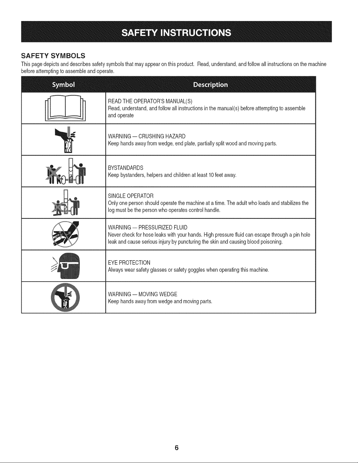
SAFETY SYMBOLS
Thispagedepictsanddescribessafetysymbolsthatmayappearonthisproduct. Read,understand,and followall instructionson the machine
beforeattemptingto assembleand operate.
i
i
'l I
READTHEOPERATOR'SMANUAL(S)
Read,understand,andfollow all instructionsin the manual(s)beforeattemptingto assemble
andoperate
WARNING-- CRUSHINGHAZARD
Keephandsaway fromwedge,end plate,partiallysplitwood andmovingparts.
BYSTANDARDS
Keepbystanders,helpersandchildrenat least 10feet away.
SINGLEOPERATOR
Onlyonepersonshouldoperatethe machineat a time.The adultwho loadsand stabilizesthe
logmustbethe personwho operatescontrol handle.
WARNING-- PRESSURIZEDFLUID
Nevercheckfor hoseleaks with yourhands.High pressurefluidcan escapethrougha pin hole
leakandcauseseriousinjuryby puncturingthe skin and causingbloodpoisoning.
EYEPROTECTION
Alwayswear safetyglassesor safetygoggleswhenoperatingthismachine.
WARNING-- MOVINGWEDGE
Keephandsaway fromwedgeand movingparts.
6
Useextremecautionunpackingthismachine.Somecomponentsare
veryheavyandwill requireadditionalpeopleor mechanicalhandling
equipment.
NOTE:Yourlog splitteris shippedwithmotoroilinthe engine.However,
youMUSTcheckthe oil levelbeforeoperating.Be carefulnot tooverfill.
NOTE:All referencesin thismanualto the leftor right sideof the log
splitterarefromtheoperatingpositiononly.SeeOperatorZonein the
Operationsectionof the Safetyinstructions.
UNPACKING & ASSEMBLING THE LOG
SPLITTER
TOOLS NEEDED: Safetyglasses,leathergloves,wirecutters,prybar
and/orclawhammer.
1. Use a pry bar or claw hammerto loosenand removethe topof
thecrate.
2. Use a pry bar or claw hammerto removethe sidesof thecrate,
beginningwiththe short sides(or left and rightsideof the log
splitter).Setthe sides of the crateasideto avoid injury.
3. On the frontsideof the cratethetongueassemblyis attachedon
the insideof thecratewitha cabletie.Cutthe cabletie to remove
thetongue.
4. Removethe largeplasticcoveranddiscard.
Do NOTremoveanywoodor cutany strapssecuringthe log splitter
[ or its componentsto the log splitteror thecrateat this time. Only
[ removestrapsand/orwoodwhen instructedto doso.
5. inspectthe bottomof the crate for anyprotrudingstaplesor wood
splintersand remove.
6. Removeany looseparts includedwiththe log splitter(i.e. opera-
tot's manual,etc.).
7. Removethe springclip andclevispinfromthejack standon the
tongueand then pivotthe jack stand towardsthe groundintothe
operatingposition.SeeFigure1.
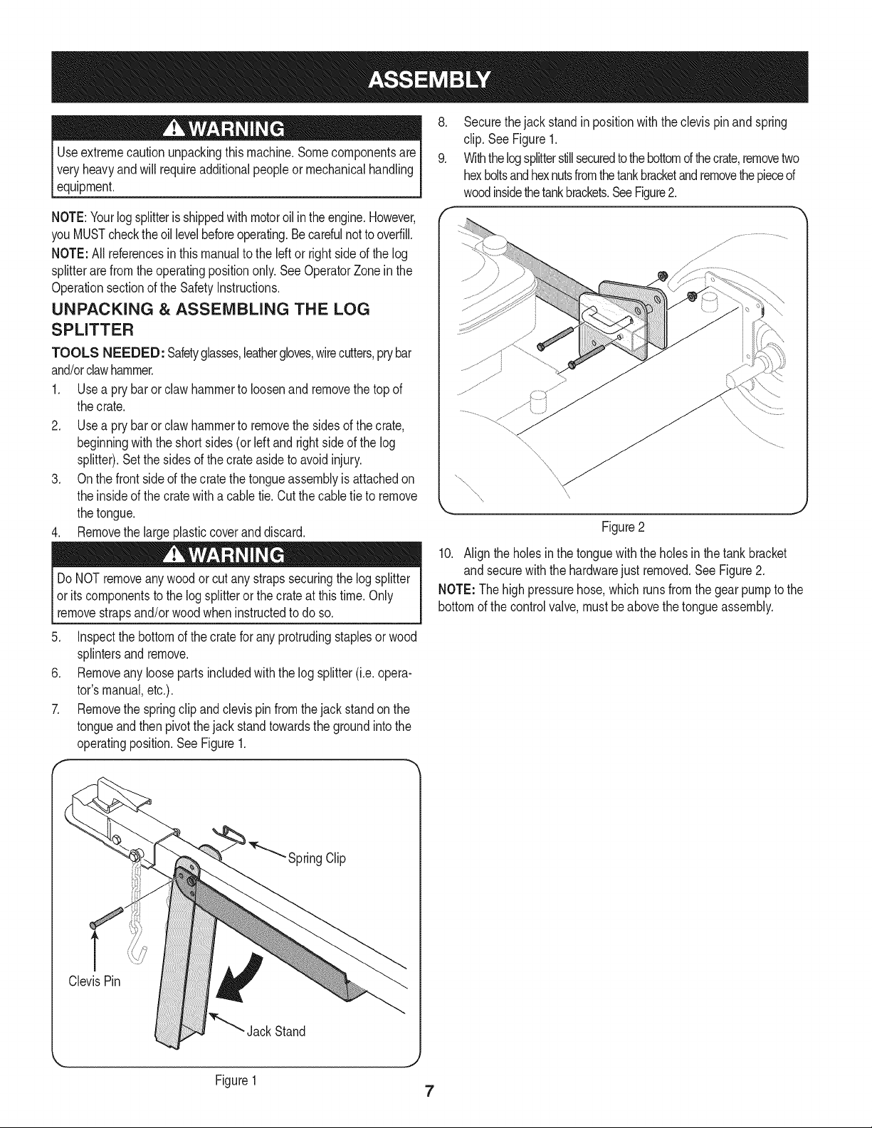
8. Securethejack standin positionwiththeclevis pinandspring
clip.See Figure1.
9. Withthelogsplitterstillsecuredtothebottomd thecrate,removetwo
hexboltsandhexnutsfromthetankbracketandremovethepieced
woodinsidethetankbrackets.SeeFigure2.
Figure2
10. Align the holesinthe tonguewith the holesinthe tankbracket
and securewith the hardwarejust removed.See Figure2.
NOTE: Thehigh pressurehose,which runsfromthe gearpumpto the
bottomof the controlvalve,mustbeabovethetongueassembly.
SpringClip
ClevisPin
Jack Stand
Figure1
7
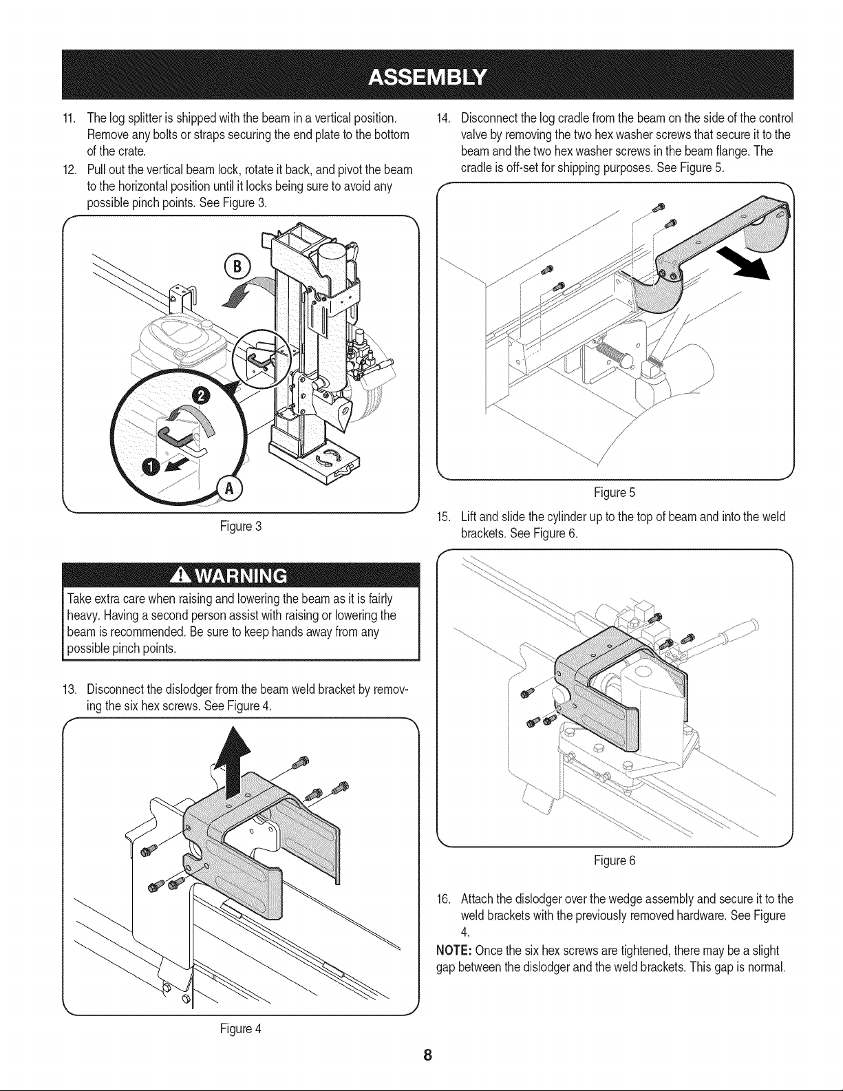
11, Thelog splitteris shippedwiththe beamin a verticalposition,
Removeanybolts or strapssecuringthe endplateto the bottom
of the crate.
12. Pull outthe verticalbeamlock, rotateit back,andpivotthe beam
to the horizontalpositionuntilit locksbeingsureto avoidany
possiblepinchpoints,See Figure3,
Figure3
14.
Disconnectthe logcradlefromthe beamon theside of the control
valveby removingthe two hexwasherscrewsthatsecureit to the
beamand the twohex washerscrewsin the beamflange.The
cradleis off-set for shippingpurposes.SeeFigure5.
15.
Figure5
Liftandslidethe cylinderup to the top of beamand intothe weld
brackets.See Figure6.
Takeextracarewhen raisingandloweringthe beamas it is fairly
heavy.Havinga secondpersonassist with raisingor loweringthe
beamis recommended.Be sureto keephandsawayfromany
possiblepinchpoints.
13. Disconnectthe dislodgerfromthe beamweld bracketby remov-
ingthe six hex screws.See Figure4.
f -,
\
Figure4
Figure6
16. Attachthe dislodgeroverthe wedgeassemblyand secureit to the
weld bracketswith the previouslyremovedhardware.SeeFigure
4.
NOTE:Oncethe six hex screwsaretightened,theremaybea slight
gap betweenthe dislodgerand theweld brackets.This gap is normal.
8
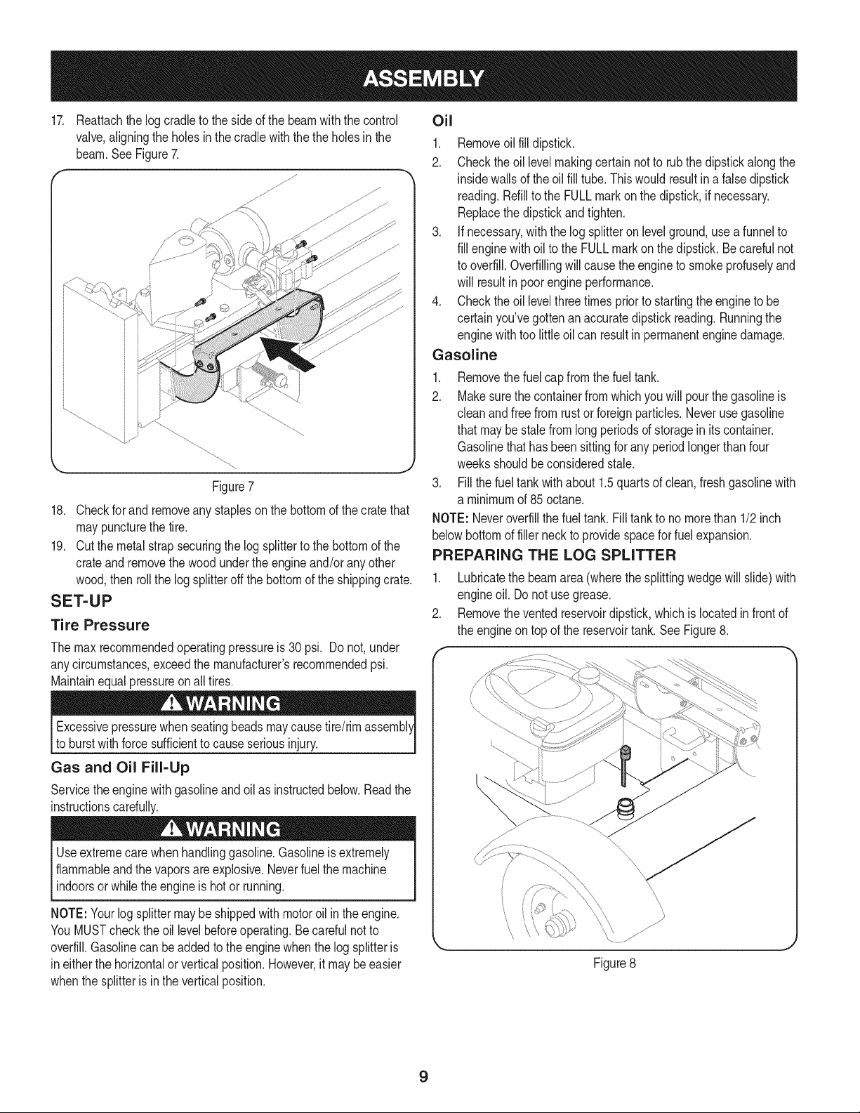
17. Reattachthe logcradleto the sideof the beamwiththe control Oil
valve,aligningthe holesin thecradlewiththe the holesin the
beam.SeeFigure7.
....fJ
J
Figure7
18. Checkfor and removeany staplesonthe bottomof the cratethat
maypuncturethe tire.
19. Cut the metalstrapsecuringthe log splitterto the bottomof the
crateand removethe woodunderthe engineand/orany other
wood,then roll the logsplitteroffthe bottomof the shippingcrate.
SET-UP
Tire Pressure
The max recommendedoperatingpressureis 30 psi. Do not,under
anycircumstances,exceedthe manufacturer'srecommendedpsi.
Maintainequalpressureon alltires.
Excessivepressurewhen seatingbeadsmaycausetire/rim
to burstwith force sufficientto cause seriousinjury.
Gas and Oil Fill-Up
Servicethe enginewith gasolineandoil as instructedbelow.Readthe
instructionscardully.
Useextremecarewhenhandlinggasoline.Gasolineis extremely
flammableand the vaporsareexplosive.Neverfuelthe machine
indoorsor whilethe engineis hot or running.
NOTE:Yourlogsplittermaybe shippedwithmotoroil inthe engine.
YouMUSTchecktheoil levelbeforeoperating.Be carefulnot to
overfill.Gasolinecan be addedto theenginewhenthe log splitteris
ineitherthe horizontalor verticalposition.However,it maybe easier
whenthe splitteris inthe verticalposition.
1. Removeoil fill dipstick.
2. Checkthe oil levelmakingcertain notto rub the dipstickalongthe
insidewallsof the oilfill tube. This wouldresultin a falsedipstick
reading.Refillto the FULLmark on the dipstick,if necessary.
Replacethe dipstickand tighten.
3. If necessary,withthe log splitteron levelground,use a funnelto
fill enginewith oil to the FULLmarkonthe dipstick.Be carefulnot
to overfill.Overfillingwillcause the engineto smokeprofuselyand
will resultinpoorengineperformance.
4. Checkthe oil levelthreetimes priorto startingthe engineto be
certainyou'vegotten an accuratedipstickreading.Runningthe
enginewithtoo little oil can resultin permanentenginedamage.
Gasoline
1. Removethe fuelcap fromthe fueltank.
2. Makesurethe containerfromwhichyou will pourthe gasolineis
cleanandfree from rust or foreignparticles.Neverusegasoline
that maybe stalefrom long periodsof storagein its container.
Gasolinethat has beensittingforany periodlongerthan four
weeksshouldbeconsideredstale.
3. Fillthe fueltankwithabout 1.5quartsof clean, freshgasolinewith
a minimumof 85 octane.
NOTE: Neveroverfillthe fueltank. Filltank to no morethan 1/2inch
belowbottomof fillerneck to providespacefor fuelexpansion.
PREPARING THE LOG SPLITTER
1. Lubricatethe beamarea(wherethe splittingwedgewillslide) with
engineoil. Donot usegrease.
2. Removethe ventedreservoirdipstick,whichis locatedin front of
the engineon topof the reservoirtank.SeeFigure8.
\
\
jj
\
Figure8
9
NOTE:Thelogsplitterisfilledto theproperoperatinglevelfromthemanu-
facturerwithShellTellus®32 HydraulicFluid.However,youMUSTcheckthe
fluidlevelbeforeoperating.Ifnotfilled,proceedwiththefollowingsteps:
Muchd the originalfluid hasbeendrawnintothe cylinderand hoses.
Makecertainto refillthe reservoirto preventdamageto the hydraulic
pump.
3. Checkthefluid levelusingthedipstick.SeeFigure8. Do not
overfill.
4. Replacetheventeddipsticksecurely,tighteningit untilthe topof
the threadsare flush with top of the pipe.
5. Disconnectthe spark plugand primethe pumpby pullingthe
recoilstarteras faras it will go. Repeatapproximately10times.
6. Reconnectthe sparkplugwireandstart the enginefollowingthe
instructionsin the Operationsection.
7. Use thecontrol handleto engagethewedgeto the farthest
extendedposition.Then retractthe wedge.
8. Refillthe tankas specifiedon thedipstick.
NOTE: Failureto refillthe tank willvoid the splitter'swarranty.
9. Extendand retractthewedge 12completecyclesto removeany
airtrappedinthe system(thesystemis "self-bleeding").
10. Refillthe reservoirwithinthe rangemarkedon the dipstick.
NOTE:Somefluid mayoverflowfromthe vent plugas the system
buildsheatandthe fluidexpandsandseeksa balancedlevel.
10
Cylinder
CouI
Hitch
;lodger
ControlHandle
Horizontal
BeamLock
BeamAssembly
Tongue
Plate
Engi
StarterHandle
Vertical
Beam
Lock
Tray
Reservoir
Tank
Fi,
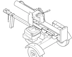
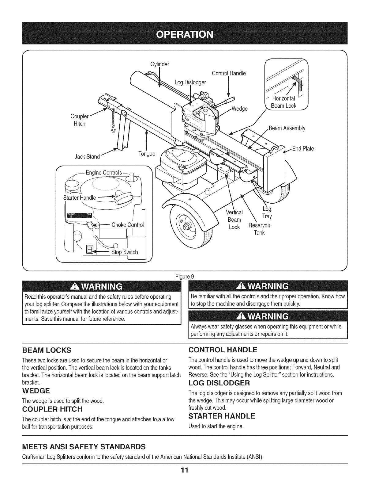
Readthis operator'smanualand the safetyrulesbeforeoperating
yourlogsplitter.Comparethe illustrationsbelowwithyourequipment
to familiarizeyourselfwith the locationof variouscontrolsandadjust-
ments.Savethis manualfor futurereference.
ure 9
Befamiliarwithall the controlsand their properoperation.Knowhow
to stop the machineanddisengagethemquickly.
Alwayswear safetyglasseswhenoperatingthisequipmentorwhile
performinganyadjustmentsor repairson it.
BEAM LOCKS
Thesetwolocksare usedto securethe beamin the horizontalor
theverticalposition.The verticalbeamlockis locatedon the tanks
bracket.The horizontalbeamlockis locatedonthe beamsupportlatch
bracket.
WEDGE
Thewedgeis usedto splitthe wood.
COUPLER HITCH
Thecouplerhitchis at theend of the tongueandattachesto a a tow
ballfor transportationpurposes.
CONTROL HANDLE
The controlhandleis usedto movethewedgeup anddownto split
wood.Thecontrolhandlehas threepositions;Forward,Neutraland
Reverse.Seethe "Usingthe LogSplitter"sectionfor instructions.
LOG DISLODGER
The log dislodgeris designedto removeany partiallysplitwoodfrom
the wedge.This mayoccur whilesplittinglargediameterwoodor
freshlycutwood.
STARTER HANDLE
Usedto startthe engine.
MEETS ANSI SAFETY STANDARDS
CraftsmanLogSplittersconformto the safetystandardof the AmericanNationalStandardsInstitute(ANSI).
11
LOG TRAY
Thelog trayis designedto catchthe log after it is split,
END PLATE
Theend plateholdsthelog in placewhilethe wedgesplitsthe log.
TONGUE
Thetongueis usedto attachto a towingvehiclefor transportation.
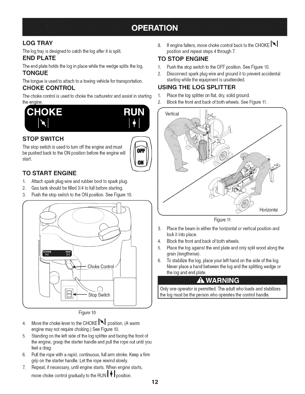
CHOKE CONTROL
Thechokecontrolis usedto chokethe carburetorandassistinstarting
the encinc.
8. If enginefalters, movechoke controlbackto the CHOKEt'°,1
positionand repeatsteps4 through7.
TO STOP ENGINE
1. Pushthe stop switchto the OFF position.SeeFigure10.
2. Disconnectsparkplugwireandgroundit to preventaccidental
startingwhilethe equipmentis unattended.
USING THE LOG SPLITTER
1, Placethe log splitteron flat, dry,solidground,
2, Blockthe frontandbackof bothwheels.See Figure11.
STOP SWITCH
Thestopswitchis usedto turnoff the engineandmust
bepushedbackto the ON positionbeforethe enginewill
start.
TO START ENGINE
1. Attachsparkplug wireand rubberbootto spark plug.
2. Gastank shouldbe filled 3/4 to full beforestarting.
3. Pushthe stopswitchto the ONposition.See Figure10.
f
ChokeControli
Stop Switch
Vertical
Horizontal
Figure11
3. Placethe beamin either thehorizontalor verticalpositionand
lockit intoplace.
4. Blockthe frontandbackof bothwheels.
5. Placethe log againstthe endplateandonly split woodalongthe
grain(lengthwise).
6. To stabilizethelog, placeyourleft handon the sideof the log.
Neverplacea handbetweenthe log and thesplittingwedgeor
the log and endplate.
Onlyoneoperatoris permitted.Theadultwho loadsandstabilizes
the log mustbe the personwhooperatesthecontrolhandle.
Figure10
4. Movethe chokeleverto the CHOKElxl pos t on.(Awarm
enginemaynot requirechoking.)SeeFigure10.
5. Standingonthe left sideof the log splitterandfacingthe front of
the engine,graspthe starterhandleand pull the ropeout until you
feela drag.
6. Pull the ropewitha rapid,continuous,full armstroke.Keepa firm
griponthe starterhandle.Letthe roperewindslowly.
7. Repeat,if necessary,untilenginestarts.Whenenginestarts,
movechokecontrolgraduallyto the RUN'_{ I position.
12
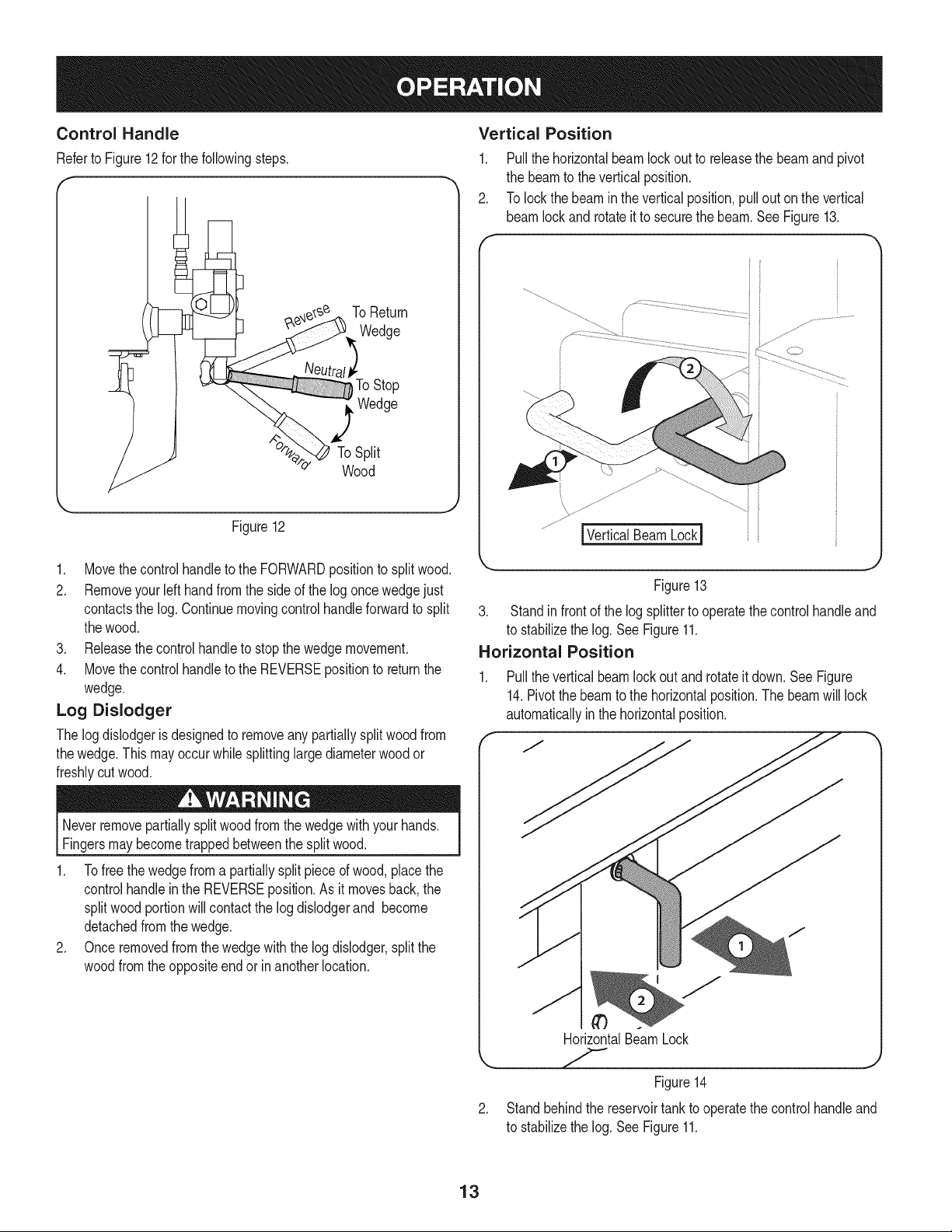
Control Handle
Referto Figure12 forthe followingsteps.
To Return
Wedge
_ToStop
_ Wedge
To Split
Wood
Figure12
1. Movethe controlhandleto the FORWARDpositionto splitwood.
2. Removeyour left hand fromthe sideof the log oncewedgejust
contactsthe log. Continuemovingcontrolhandleforwardto split
thewood.
3. Releasethe controlhandleto stopthe wedgemovement.
4. Movethe controlhandleto the REVERSEpositionto returnthe
wedge.
Log Dislodger
The log dislodgeris designedto removeanypartiallysplit woodfrom
thewedge.Thismayoccurwhilesplittinglarge diameterwoodor
freshlycut wood.
Neverremovepartiallysplitwoodfromthe wedgewithyour hands.
Fingersmaybecometrappedbetweenthe splitwood.
1. Tofreethe wedgefroma partiallysplit pieceof wood,placethe
controlhandleinthe REVERSEposition.As it movesback,the
splitwoodportionwillcontactthe logdislodgerand become
detachedfromthe wedge.
2. Onceremovedfrom the wedgewith the logdislodger,splitthe
woodfromtheoppositeendor inanotherlocation.
Vertical Position
1. Pullthe horizontalbeamlockout to releasethe beamandpivot
the beamto the verticalposition.
2. To lockthebeaminthe verticalposition,pullout on the vertical
beamlockand rotateit to securethe beam.See Figure13.
f
......................................................................................................:J.........................................
Figure13
3. Standin front of the log splitterto operatethe controlhandleand
to stabilizethe log. See Figure11.
Horizontal Position
Pullthe verticalbeamlock out androtateitdown.SeeFigure
14.Pivotthe beamto the horizontalposition.The beamwill lock
automaticallyinthe horizontalposition.
HorizontalBeamLock
.
Figure14
Standbehindthe reservoirtank to operatethe controlhandleand
to stabilizethe log. See Figure11.
13
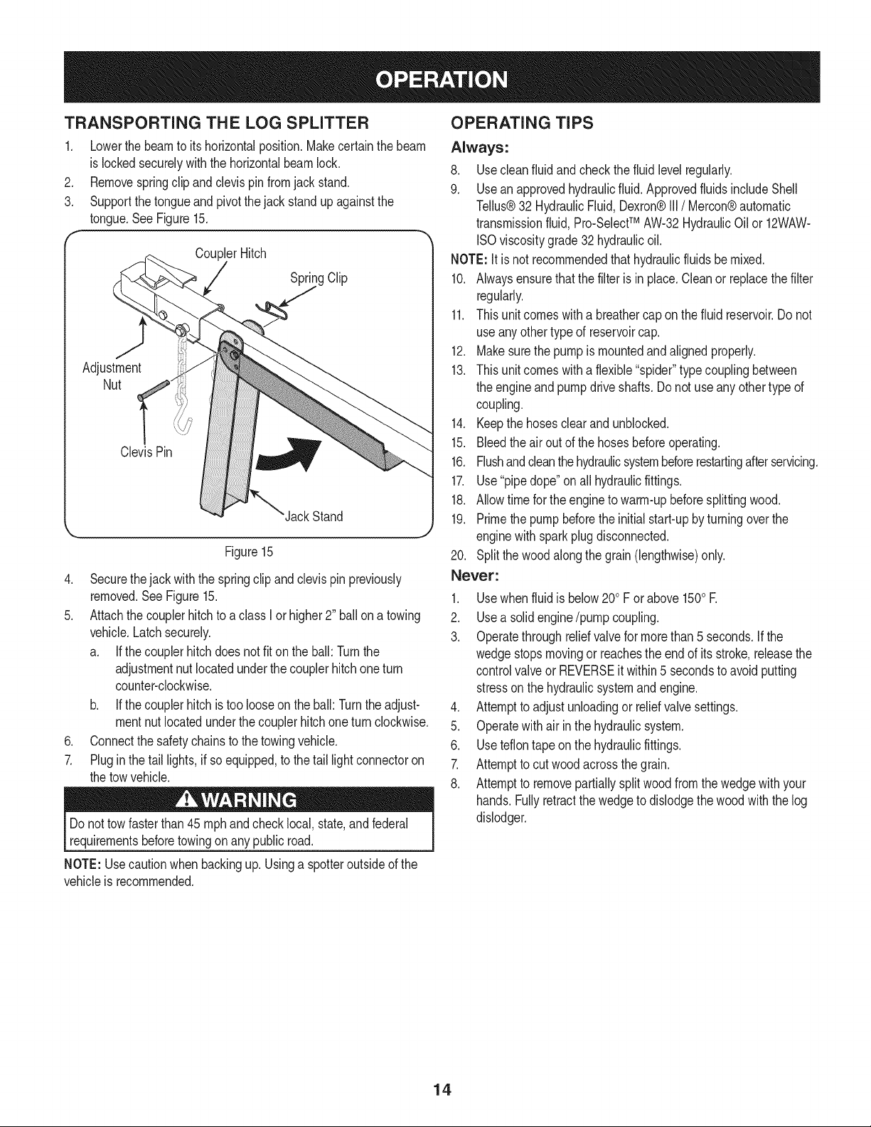
TRANSPORTING THE LOG SPLITTER
1. Lowerthe beamto itshorizontalposition.Makecertainthe beam
islockedsecurelywith the horizontalbeamlock.
2. Removespringclip andclevispinfromjackstand.
3. Supportthe tongueand pivotthe jackstand up againstthe
tongue.SeeFigure15.
f
CouplerHitch
Spritg Clip
Adjustment
Nut
ClevisPin
JackStand
Figure15
4. Securethejack withthe springclipand clevispinpreviously
removed.See Figure15.
5. Attachthecouplerhitch to a classI or higher2" ballona towing
vehicle.Latch securely.
a. If thecouplerhitchdoesnot fit on the ball:Turnthe
adjustmentnutlocatedunderthecouplerhitchone turn
counter-clockwise.
b. If thecouplerhitchis too looseonthe ball: Turnthe adjust-
mentnutlocatedunderthecouplerhitchoneturn clockwise.
6. Connectthe safetychainsto the towingvehicle.
7. Plug in the tail lights,if so equipped,to the tail lightconnectoron
the towvehicle.
Do nottow fasterthan45 mphandchecklocal,state,andfederal
requirementsbeforetowingon any publicroad.
NOTE: Usecautionwhenbackingup. Usinga spotteroutsideof the
vehicleis recommended.
OPERATING TiPS
Always:
8. Usecleanfluid andcheckthefluid levelregularly.
9. Usean approvedhydraulicfluid. ApprovedfluidsincludeShell
Tellus®32 HydraulicFluid,Dexron®III/ Mercon®automatic
transmissionfluid, Pro-SelectTM AW-32HydraulicOil or 12WAW-
ISOviscositygrade32 hydraulicoil.
NOTE:It is not recommendedthat hydraulicfluids be mixed.
10. Alwaysensurethatthe filter is in place.Cleanor replacethe filter
regularly.
11. This unit comeswitha breathercap on the fluid reservoir.Do not
useanyothertypeof reservoircap.
12. Makesurethe pumpis mountedandalignedproperly.
13. This unit comeswitha flexible"spider"typecouplingbetween
the engineand pumpdriveshafts. Donot useany othertypeof
coupling.
14. Keepthe hosesclearandunblocked.
15. Bleedthe airout of the hosesbeforeoperating.
16. Flushand cleanthehydraulicsystembeforerestartingafterservicing.
17. Use"pipedope"on all hydraulicfittings.
18. Allowtime for the engineto warm-upbeforesplittingwood.
19. Primethe pumpbeforethe initial start-upby turningoverthe
enginewith sparkplugdisconnected.
20. Splitthewood alongthe grain(lengthwise)only.
Never:
1. Usewhenfluid is below200F orabove 1500R
2. Usea solidengine/pumpcoupling.
3. Operatethroughreliefvalvefor morethan5 seconds.If the
wedgestopsmovingor reachesthe endof its stroke,releasethe
controlvalveor REVERSEit within5 secondsto avoidputting
stressonthe hydraulicsystemandengine.
4. Attemptto adjustunloadingor reliefvalvesettings.
5. Operatewithair inthe hydraulicsystem.
6. Useteflontape onthe hydraulicfittings.
7. Attemptto cutwoodacrossthe grain.
8. Attemptto removepartiallysplit woodfromthe wedgewithyour
hands.Fullyretractthewedgeto dislodgethe woodwiththe log
dislodger.
14
Do notat any time makeanyadjustmentswithoutfirststopping
theengine,disconnectingspark plugwire andgroundingit against
theengine.Alwayswearsafetyglassesduringoperationor while
_performng anyadjustmentsor repars.
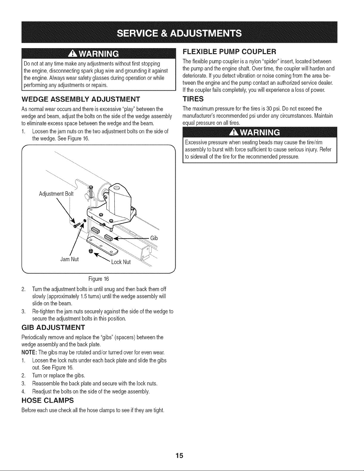
WEDGE ASSEMBLY ADJUSTMENT
As normalwearoccursandthereis excessive"play"betweenthe
wedgeand beam,adjustthe bolts on the sideof the wedgeassembly
to eliminateexcessspacebetweenthe wedgeandthe beam.
1. Loosenthejam nutson the twoadjustmentboltson the sideof
thewedge.See Figure16.
AdjustmentBolt
Jam Nut
' LockNut
Gib
FLEXIBLE PUMP COUPLER
Theflexiblepumpcoupleris a nylon"spider"insert,locatedbetween
the pumpand theengineshaft.Overtime,the couplerwill hardenand
deteriorate.If you detectvibrationor noisecomingfromthe areabe-
tweenthe engineand the pumpcontactanauthorizedservicedealer.
If thecouplerfailscompletely,you will experiencea loss of power.
TIRES
The maximumpressurefor thetiresis 30psi.Do not exceedthe
manufacturer'srecommendedpsi underanycircumstances.Maintain
equalpressureonall tires.
Excessivepressurewhen seatingbeadsmaycausethe tire/rim
assemblyto burst with forcesufficientto causeseriousinjury.Refer
to sidewallof the tire for the recommendedpressure.
Figure16
2. Turnthe adjustmentbolts in until snugandthenbackthemoff
slowly(approximately1.5turns) untilthe wedgeassemblywill
slideonthe beam.
3. Re-tightenthe jam nutssecurelyagainst theside of the wedgeto
securethe adjustmentboltsin thisposition.
GIB ADJUSTMENT
Periodicallyremoveandreplacethe"gibs"(spacers)betweenthe
wedgeassemblyand the backplate.
NOTE:The gibsmay be rotatedand/or turnedoverfor evenwear.
1. Loosenthe lock nuts undereach backplateand slidethegibs
out.SeeFigure16.
2. Turnor replacethe gibs.
3. Reassemblethe backplateandsecurewiththe lock nuts.
4. Readjusttheboltson the sideof the wedgeassembly.
HOSE CLAMPS
Beforeeach usecheckallthe hoseclampsto see if theyaretight.
15
TASKS
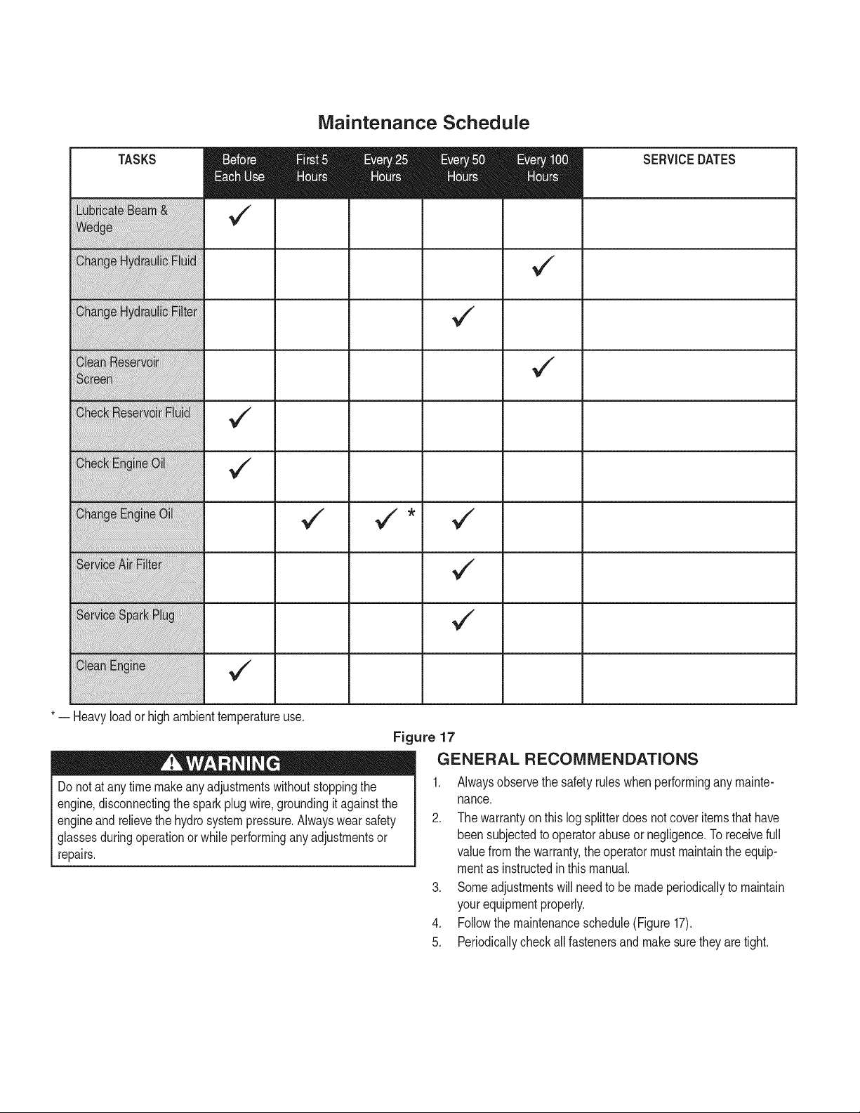
Maintenance Schedule
* -- Heavyloador highambienttemperatureuse.
Figure 17
SERVICEDATES
GENERAL RECOMMENDATIONS
Do notat any time makeanyadjustmentswithoutstoppingthe
engine,disconnectingthe sparkplugwire,groundingit againstthe
engineandrelievethe hydrosystempressure.Alwayswear safety
glassesduringoperationor whileperforminganyadjustmentsor
repairs.
1. Alwaysobservethe safety ruleswhenperformingany mainte-
nance.
2. The warrantyon this logsplitterdoesnotcoveritemsthathave
beensubjectedto operatorabuseor negligence.Toreceivefull
valuefromthe warranty,the operatormust maintainthe equip-
mentas instructedin thismanual.
3. Someadjustmentswill needto be madeperiodicallyto maintain
yourequipmentproperly.
4. Followthe maintenanceschedule(Figure 17).
5. Periodicallycheckall fastenersand makesurethey are tight.
HYDRAULIC FLUID AND iNLET FILTER
Stopthe engineand relievehydraulicsystem )ressurebeforechang-
ingor adjustingfittings,hoses,tubing,or othersystemcomponents.
Checkthehydraulicfluid levelin the log splitterreservoirtankbefore
eachuse.Maintainthe fluid levelwithinthe rangespecifiedon the
dipstickat all times.
Changethe hydraulicfluid in the reservoirevery100hoursof opera-
tion.Followthe stepsbelow:
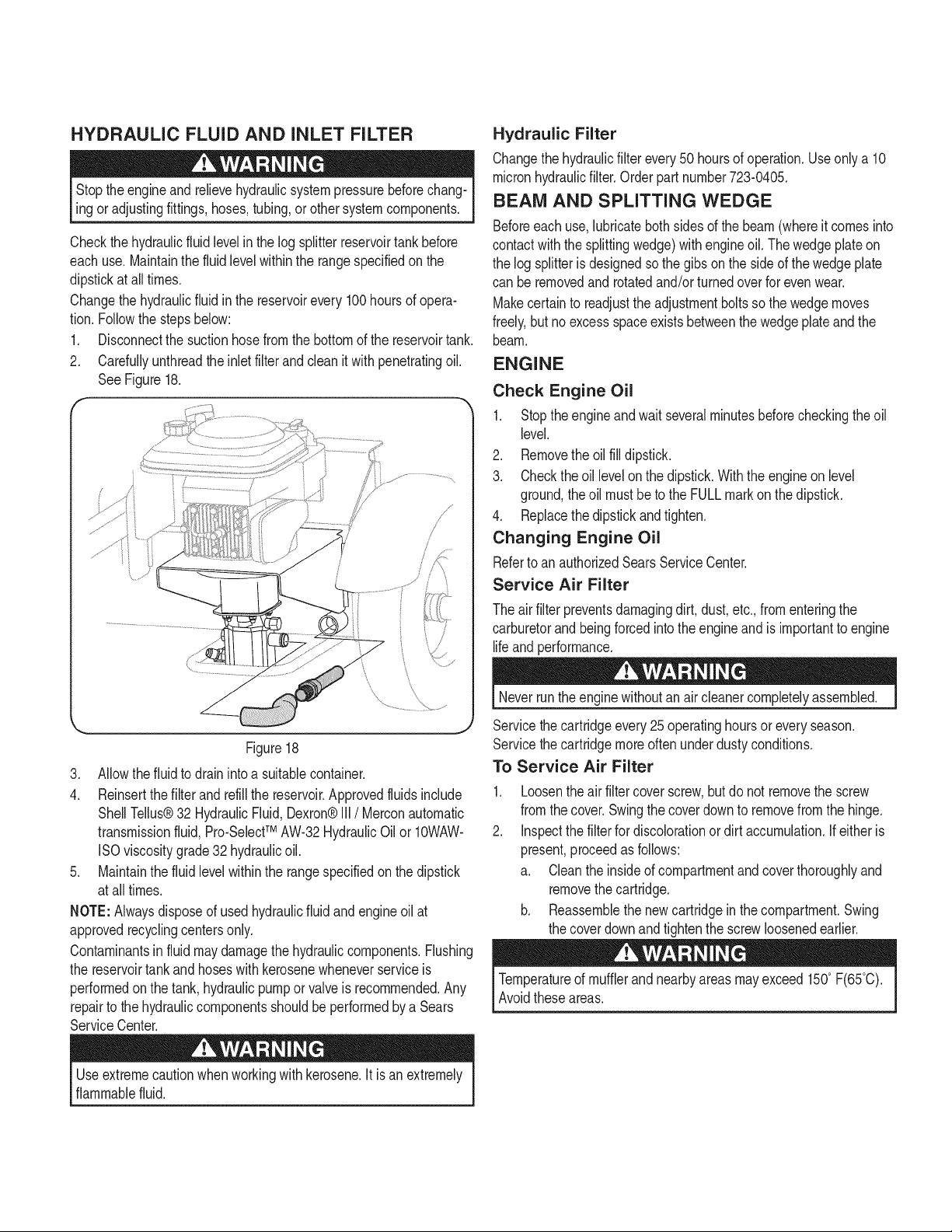
1. Disconnectthe suctionhosefromthe bottomof the reservoirtank.
2. Carefullyunthreadthe inletfilterandclean it withpenetratingoil.
SeeFigure18.
f -,
J, ................................................
.......I i
/
/
p
/
\
\
\ \
,,J
Figure18
3. Allowthefluid to drain intoa suitablecontainer.
4. Reinsertthe filter and refillthe reservoir.Approvedfluidsinclude
ShellTellus®32 HydraulicFluid,Dexron®III / Merconautomatic
transmissionfluid, Pro-SelectTM AW-32HydraulicOil or 10WAW-
ISOviscositygrade32 hydraulicoil.
5. Maintainthe fluid levelwithinthe rangespecifiedon the dipstick
at all times.
NOTE:Alwaysdisposeof usedhydraulicfluidandengineoil at
approvedrecyclingcentersonly.
Contaminantsin fluidmaydamagethe hydrauliccomponents.Flushing
the reservoirtank and hoseswith kerosenewheneverserviceis
performedonthe tank, hydraulicpumpor valveis recommended.Any
repairto the hydrauliccomponentsshouldbe performedby a Sears
ServiceCenter.
Hydraulic Filter
Changethehydraulicfilter every 50 hoursof operation.Useonlya 10
micronhydraulicfilter.Orderpartnumber723-0405.
BEAM AND SPLITTING WEDGE
Beforeeachuse, lubricateboth sidesof the beam(whereit comesinto
contactwiththe splittingwedge)withengineoil. The wedgeplateon
the log splitteris designedsothe gibs onthe sideof thewedgeplate
can be removedandrotatedand/or turnedoverfor evenwear.
Makecertainto readjusttheadjustmentboltsso the wedgemoves
freely,butno excessspaceexistsbetweenthe wedgeplateandthe
beam.
ENGINE
Check Engine Oil
1. Stoptheengineandwait severalminutesbeforecheckingtheoil
level.
2. Removethe oil fill dipstick.
3. Checkthe oil levelon the dipstick.With the engineon level
ground,theoil mustbeto the FULLmarkon thedipstick.
4. Replacethe dipstickandtighten.
Changing Engine Oil
Referto anauthorizedSearsServiceCenter.
Service Air Filter
The air filter preventsdamagingdirt, dust, etc.,fromenteringthe
carburetorandbeingforcedintothe engineandis importantto engine
lifeandperformance.
Neverrunthe enginewithoutan air cleanercompletelyassembled.
Servicethecartridgeevery25operatinghoursoreveryseason.
Servicethecartridgemoreoftenunderdusty conditions.
To Service Air Filter
.
2.
Loosentheair filtercoverscrew,butdo not removethe screw
fromthe cover.Swingthecoverdownto removefrom the hinge.
Inspectthe filter for discolorationor dirt accumulation.If either is
present,proceedas follows:
a. Cleanthe insideof compartmentand coverthoroughlyand
removethe cartridge.
b. Reassemblethenew cartridgeinthe compartment.Swing
the coverdownand tightenthe screwloosenedearlier.
Temperatureof mufflerand nearbyareasmayexceed150° F(65°C).
Avoidtheseareas.
Useextremecautionwhen workingwith kerosene.It is anextremely
flammablefluid.
Service Spark Plug
1. Cleanthe sparkplugandresetthe gap to .030"at leastonce a
seasonorevery50hoursof operation.
2. Cleanthearea aroundthe sparkplug. Removeandinspectthe
sparkplug.
3. Replacethe sparkplugif the electrodesare pitted,burnedorthe
porcelainis cracked.
NOTE:Contacta SearsPartsand RepairCenteror 1-800-4-MY-
HOME®for a replacementsparkplug,Champion®partnumber
RJ19LM.
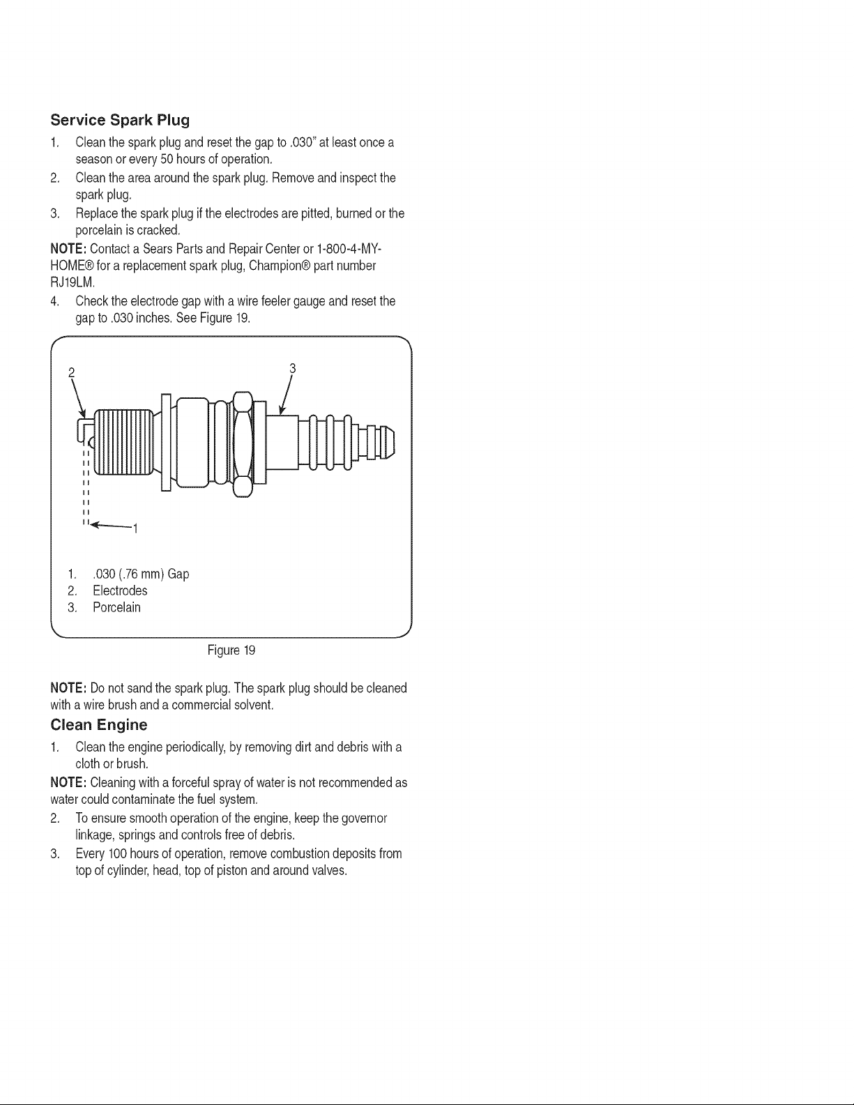
4. Checkthe electrodegap with a wirefeelergaugeand resetthe
gapto .030inches.See Figure19.
2
\
mm
ii
114F---___1
3
r!
1. .030(.76 ram) Gap
2. Electrodes
3. Porcelain
Figure19
NOTE: Donot sandthe sparkplug.The sparkplugshouldbecleaned
witha wirebrushanda commercialsolvent.
Clean Engine
1. Cleantheengine periodically,by removingdirt and debriswith a
clothorbrush.
NOTE: Cleaningwitha forcefulsprayof wateris not recommendedas
watercouldcontaminatethe fuel system.
2. Toensuresmoothoperationof theengine,keepthe governor
linkage,springsandcontrolsfreeof debris.
3. Every 100hoursof operation,removecombustiondepositsfrom
topof cylinder,head,top of pistonand aroundvalves.
Prepareyourlogsplitterforstorageattheendoftheseasonorifthe
logsplitterwillnotbeusedfor30daysormore.
Neverstorethemachinewithfuelinthefueltankinsideofbuilding
wherefumesmayreachanopenflameorsparkorwhereignition
sourcesarepresentsuchashotwaterandspaceheaters,furnaces,
clothesdyers,stoves,electricmotors,etc.
NOTE:Ayearlycheck-upbyyourlocalSearsservicecenterisagood
waytoensureyourlogsplitterwillprovidethemaximumperformance
nextseason.
LOG SPLITTER
1. Cleanthe logsplitterthoroughly.
2. Wipethe logsplitterwithanoiledragto preventrust,especially
onthe wedgeand the beam.
ENGINE
NOTE: It is importantto preventgumdepositsfromformingin the
essentialfuel systemparts suchas the carburetor,fuelfilter,fuel hose
ortankduringstorage.Also, alcoholblendedfuels (calledgasoholor
usingethanolor methanol)can attractmoisturewhichleadsto separa-
tionandformationof acidsduringstorage.Acidic gascan damagethe
fuel systemof anenginewhile in storage.
1. Drainthe fueltankby runningthe engineuntilthe fuel linesand
carburetorareempty.Alwaysdrainthe fuel intoan approved
containeroutdoorsawayfromopenflame.Besurethe engineis
cool.Do notsmokewhile handlingthe fuel.
NOTE: Neveruse engineorcarburetorcleanerproductsinthe fuel
tankor permanentdamagemayoccur.Usefresh fuel nextseason.
2. Removethe sparkplug,pourapproximately1/2oz.of engineoil
intocylinderandcrankit slowlyto distributetheoil.
3. Replacethe sparkplug.
FUEL STABILIZER
NOTE: Fuelstabilizeris an acceptablealternativein minimizingthe
formationof fuel gumdepositsduringstorage.
Pleasefollowthe instructionsbelowfor storingyourlogsplitterwith
fuel and stabilizerinthe engine:
1. Add stabilizerto the gasolinein the fueltankor storagecontainer.
Alwaysfollow the mixratiofoundonthe stabilizercontainer.
2. Runtheengine at least10minutesafteradding stabilizerto allow
the stabilizerto reachthe carburetor.
NOTE: Do notdrainthe gastank and carburetorif usingfuelstabilizer.
Drainall the oil from the crankcase(thisshouldbedoneafterthe
enginehasbeenoperatedand is still warm)and refillthecrankcase
withfreshoil.
OTHER
• Donot storethe gasolinefrom one seasonto another.
• Replaceyourgasolinecan if it starts to rust.
Storethe log splitterin a clean,dry area.Do not storeit nextto
any corrosivematerials,suchas fertilizer.
• Wipethe equipmentwithan oiledragto preventrust.
19
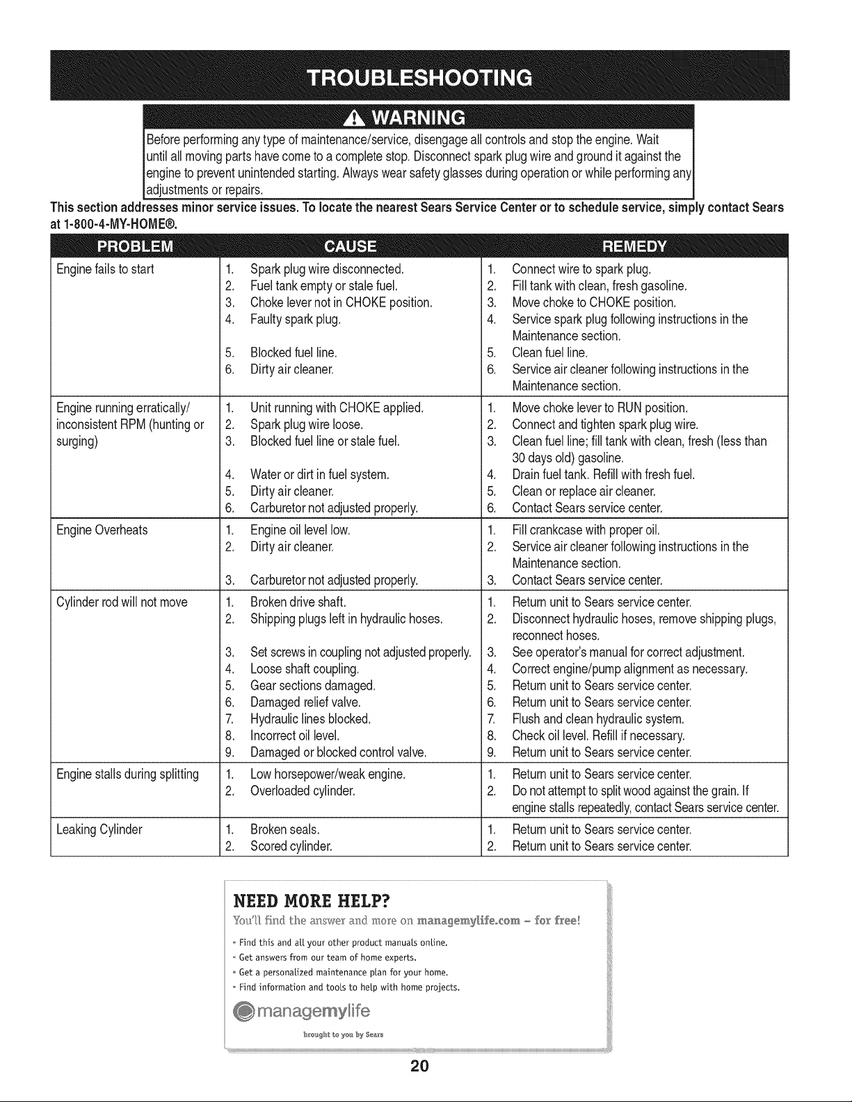
Beforeperforminganytype of maintenance/service,disengageall controlsand stopthe engine.Wait
untilall movingpartshavecometo a completestop.Disconnectsparkplugwire and groundit againstthe
engineto preventunintendedstarting.Alwayswearsafetyglassesduringoperationor whileperformingany
adjustmentsor repars.
This section addresses minor service issues. To locate the nearest Sears Service Centeror to schedule service, simply contact Sears
at 1-800-4-MY-HOME®.
1. Sparkplugwire disconnected.
2. Fueltank emptyor stalefuel.
3. Chokelevernot inCHOKEposition.
4. Faultysparkplug.
Enginefailsto start
Enginerunningerratically/
inconsistentRPM (huntingor
surging)
EngineOverheats
Cylinderrodwill not move
5. Blockedfuel line.
6. Dirtyair cleaner.
1. Unit runningwith CHOKEapplied.
2. Sparkplugwire loose.
3. Blockedfuel lineor stalefuel.
4. Wateror dirt infuel system.
5. Dirtyair cleaner.
6. Carburetornot adjustedproperly.
1. Engineoil levellow.
2. Dirtyair cleaner.
3. Carburetornot adjustedproperly.
1. Brokendriveshaft.
2. Shippingplugsleft in hydraulichoses.
3. Setscrewsin couplingnotadjustedproperly.
4. Looseshaftcoupling.
5. Gearsectionsdamaged.
6. Damagedreliefvalve.
7. Hydrauliclines blocked.
8. Incorrectoil level.
9. Damagedor blockedcontrolvalve.
1. Connectwireto spark plug.
2. Filltank with clean,fresh gasoline.
3. Movechoketo CHOKEposition.
4. Servicesparkplug followinginstructionsinthe
Maintenancesection.
5. Cleanfuel line.
6. Serviceair cleanerfollowinginstructionsin the
Maintenancesection.
1. Movechokeleverto RUNposition.
2. Connectandtightensparkplugwire.
3. Cleanfuel line;fill tankwith clean,fresh(lessthan
30daysold)gasoline.
4. Drainfuel tank. Refillwithfreshfuel.
5. Cleanor replaceair cleaner.
6. ContactSearsservicecenter.
1. Fillcrankcasewith properoil.
2. Serviceair cleanerfollowinginstructionsin the
Maintenancesection.
3. ContactSearsservicecenter.
1. Returnunitto Searsservicecenter.
2. Disconnecthydraulichoses,removeshippingplugs,
reconnecthoses.
3. Seeoperator'smanualfor correctadjustment.
4. Correctengine/pumpalignmentas necessary.
5. Returnunitto Searsservicecenter.
6. Returnunitto Searsservicecenter.
7. Flushand cleanhydraulicsystem.
8. Checkoil level.Refillif necessary.
9. Returnunitto Searsservicecenter.
Enginestallsduringsplitting 1. Lowhorsepower/weakengine. 1. Returnunitto Searsservicecenter.
2. Overloadedcylinder. 2. Donotattemptto splitwoodagainstthe grain.If
enginestallsrepeatedly,contactSearsservicecenter.
LeakingCylinder 1. Brokenseals. 1. Returnunitto Searsservicecenter.
2. Scoredcylinder. 2. Returnunitto Searsservicecenter.
NEED MORE HELP?
Y_!I_ fk@ _he answor a_(! more o_ _anagem,y_fe_cem, _ £o_° f_ee!
Find this and at[ your other product manuals online.
* Get answers from our team of home experts.
Get a personalized maintenance plan for your home.
* Find information and tools to help with home projects.
b:ro'_g_: to yea by S_&_
20
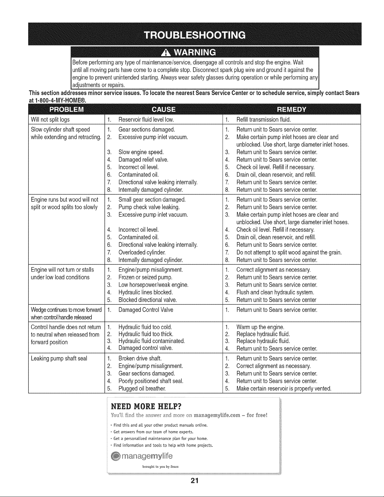
Beforeperforminganytype of maintenance/service,disengageall controlsand stopthe engine.Wait [
untilall movingpartshavecometo a completestop.Disconnectsparkplugwire and groundit againstthe [
engineto preventunintendedstarting.Alwayswear safetyglassesduringoperationor whileperformingawl
[adjustmentsor repars.
This section addresses minor service issues. To locate the nearest Sears Service Centeror to schedule service, simply contact Sears
at 1-800-4-MY-HOME®.
Will notsplit logs
Slowcylindershaftspeed
whileextendingand retracting.
Engineruns butwoodwill not
splitorwood splitstoo slowly
Enginewill notturn or stalls
underlowloadconditions
Wedgecontinuesto moveforward
whencontrolhandlereleased
Controlhandledoes notreturn
to neutralwhen releasedfrom
forwardposition
Leakingpumpshaft seal
1. Reservoirfluid levellow.
1. Gear sectionsdamaged.
2. Excessivepumpinletvacuum.
3. Slowenginespeed.
4. Damagedreliefvalve.
5. incorrectoil level.
6. Contaminatedoil.
7. Directionalvalveleakinginternally.
8. [nternallydamagedcylinder.
1. Smallgear sectiondamaged.
2. Pumpcheckvalveleaking.
3. Excessivepumpinletvacuum.
4. incorrectoil level.
5. Contaminatedoil.
6. Directionalvalveleakinginternally.
7. Overloadedcylinder.
8. [nternallydamagedcylinder.
1. Engine/pumpmisalignment.
2. Frozenor seizedpump.
3. Lowhorsepower/weakengine.
4. Hydrauliclines blocked.
5. Blockeddirectionalvalve.
1. DamagedControlValve
1. Hydraulicfluidtoo cold.
2. Hydraulicfluidtoo thick.
3. Hydraulicfluid contaminated.
4. Damagedcontrolvalve.
1. Brokendriveshaft.
2. Engine/pumpmisalignment.
3. Gear sectionsdamaged.
4. Poorlypositionedshaftseal.
5. Pluggedoil breather.
1. Refilltransmissionfluid.
1. Returnunitto Searsservicecenter.
2. Makecertainpump inlethosesareclearand
unblocked.Use short,large diameterinlet hoses.
3. Returnunitto Searsservicecenter.
4. Returnunitto Searsservicecenter.
5. Checkoil level.Refillif necessary.
6. Drainoil,clean reservoir,and refill.
7. Returnunitto Searsservicecenter.
8. Returnunitto Searsservicecenter.
1. Returnunitto Searsservicecenter.
2. Returnunitto Searsservicecenter.
3. Makecertainpump inlethosesareclearand
unblocked.Use short,large diameterinlet hoses.
4. Checkoil level.Refillif necessary.
5. Drainoil,clean reservoir,and refill.
6. Returnunitto Searsservicecenter.
7. Do notattemptto split woodagainstthe grain.
8. Returnunitto Searsservicecenter.
1. Correctalignmentas necessary.
2. Returnunitto Searsservicecenter.
3. Returnunitto Searsservicecenter.
4. Flushand cleanhydraulicsystem.
5. Returnunitto Searsservicecenter
1. Returnunitto Searsservicecenter.
1. Warmup the engine.
2. Replacehydraulicfluid.
3. Replacehydraulicfluid.
4. Returnunitto Searsservicecenter.
1. Returnunitto Searsservicecenter.
2. Correctalignmentas necessary.
3. Returnunitto Searsservicecenter.
4. Returnunitto Searsservicecenter.
5. Makecertain reservoiris properlyvented.
NEED HORE HELP?
YOu[[S;ndLheanswer andmoreonma_agemy[£e_{om- rex_h'ee!
Find this and aLLyour other product manuals online.
ii _ Get answers from our team of home experts.
ii Get a personalized maintenance plan for your home.
Find information and tools to help with home projects.
ma, nagemylife
21
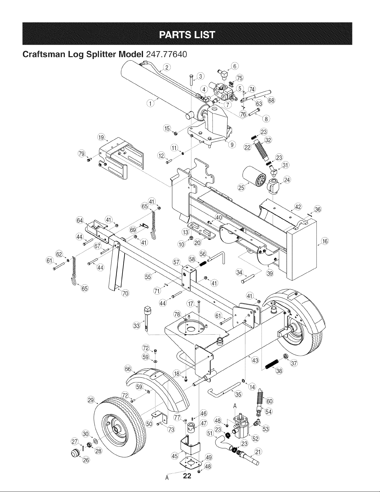
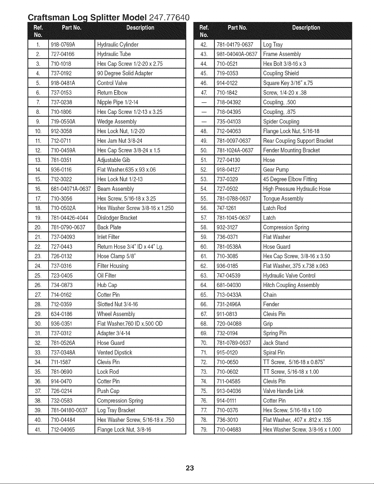
Craftsman Log Splitter Model 247.77640
Loc iVlodel 247
918-0769A
727-04166
710-1018
737-0192
918-0481A
737-0153
737-0238
710-1806
719-0550A
912-3058
712-0711
710-0459A
781-0351
936-0116
712-3022
681-04071A-0637
710-3056
710-0502A
781-04426-4044
781-0790-0637
737-04093
727-0443
726-0132
737-0316
723-0405
734-0873
714-0162
712-0359
634-0186
936-0351
737-0312
781-0526A
737-0348A
711-1587
781-0690
914-0470
726-0214
732-0583
781-04180-0637
710-04484
712-04065
HydraulicCylinder
HydraulicTube
HexCapScrew1/2-20x 2.75
90 DegreeSolidAdapter
ControlValve
ReturnElbow
NipplePipe1/2-14
HexCapScrew1/2-13x 3.25
WedgeAssembly
HexLockNut, 1/2-20
HexJamNut3/8-24
HexCapScrew3/8-24 x 1.5
AdjustableGib
FiatWasher.635x.93x.06
HexLockNut1/2-13
BeamAssembly
HexScrew,5/16-18x 3.25
HexWasherScrew3/8-16x 1.250
DislodgerBracket
BackPlate
inlet Filter
ReturnHose3/4" IDx 44" Lg.
HoseClamp5/8"
FilterHousing
Oil Filter
Hub Cap
CotterPin
SlottedNut3/4-16
WheelAssembly
FlatWasher.760IDx.500OD
Adapter3/4-14
HoseGuard
VentedDipstick
ClevisPin
LockRod
CotterPin
PushCap
CompressionSpring
LogTrayBracket
HexWasherScrew,5/16-18x .750
FlangeLockNut,3/8-16
781-04179-0637
981-04040A-0637
710-0521
719-0353
914-0122
710-1842
718-04392
718-04395
735-04103
712-04063
781-0097-0637
781-1024A-0637
727-04130
918-04127
737-0329
727-0502
781-0788-0637
747-1261
781-1045-0637
932-3127
736-0371
781-0538A
710-3085
936-0185
747-04539
681-04030
713-0433A
731-2496A
911-0813
720-04088
732-0194
781-0789-0637
915-0120
710-0650
710-0602
711-04585
913-04036
914-0111
710-0376
736-3010
710-04683
LogTray
FrameAssembly
HexBolt3/8-16x 3
CouplingShield
SquareKey3/16" x.75
Screw,1/4-20x .38
Coupling,.500
Coupling,.875
SpiderCoupling
FlangeLock Nut,5/16-18
RearCouplingSupportBracket
FenderMountingBracket
Hose
GearPump
45 DegreeElbowFitting
HighPressureHydraulicHose
TongueAssembly
LatchRod
Latch
CompressionSpring
FlatWasher
HoseGuard
HexCap Screw,3/8-16x 3.50
FiatWasher,.375x.738x.063
HydraulicValveControl
HitchCouplingAssembly
Chain
Fender
ClevisPin
Grip
SpringPin
Jack Stand
SpiralPin
TT Screw, 5/16-18x 0.875"
TT Screw,5/16-18x 1.00
ClevisPin
ValveHandleLink
CotterPin
HexScrew,5/16-18x 1.00
FiatWasher,.407x .812x .135
HexWasherScrew,3/8-16x 1.000
23
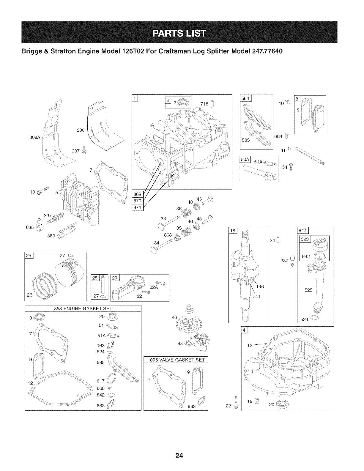
Briggs & Stratton Engine IViodel 126T02 For Craftsman Log Splitter IViodel 247.77640
306A
306
26
3
7
585
32
46
43
1095 VALVE GASKET SET
10_
684 _
L5_ 51Ac(.c 5.o_
54
1_£1
_4_
842 _-i[_ _
525
524 '\_-_
22
24
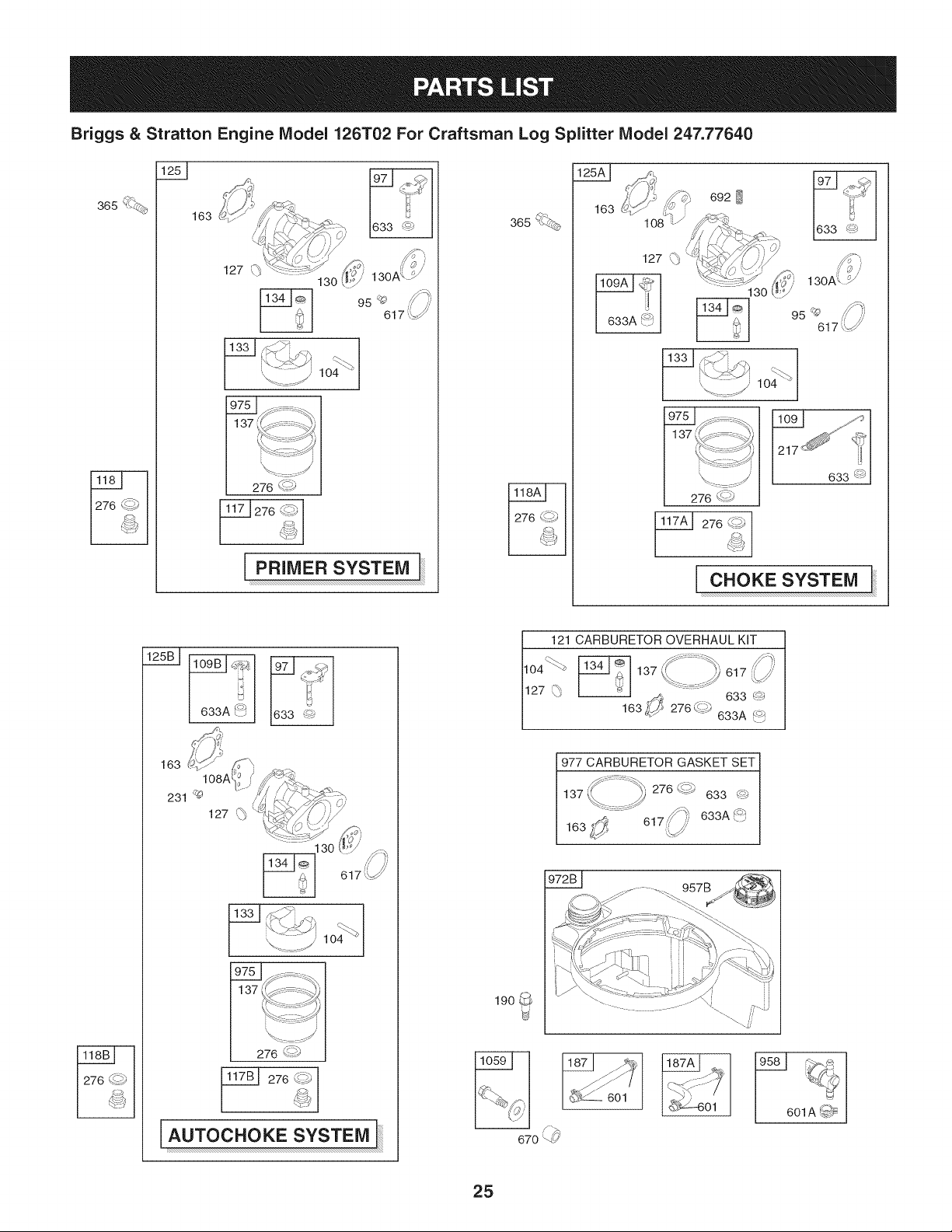
Briggs & Stratton Engine IViodel 126T02 For Craftsman Log Splitter IViodel 247.77640
365 '%.©_
163
PRIMER SYSTEM
365 ",_
163
127 \p
_J
633A _'_
692
130
276 _s
633 @
276 ¢_i_
CHOKE SYSTEM
633A _:J 1633 I
AUTOC#OKESYSTEa]
1_601
/ i_,
670 _
_-6 o
ii_ _
i
601A _
25
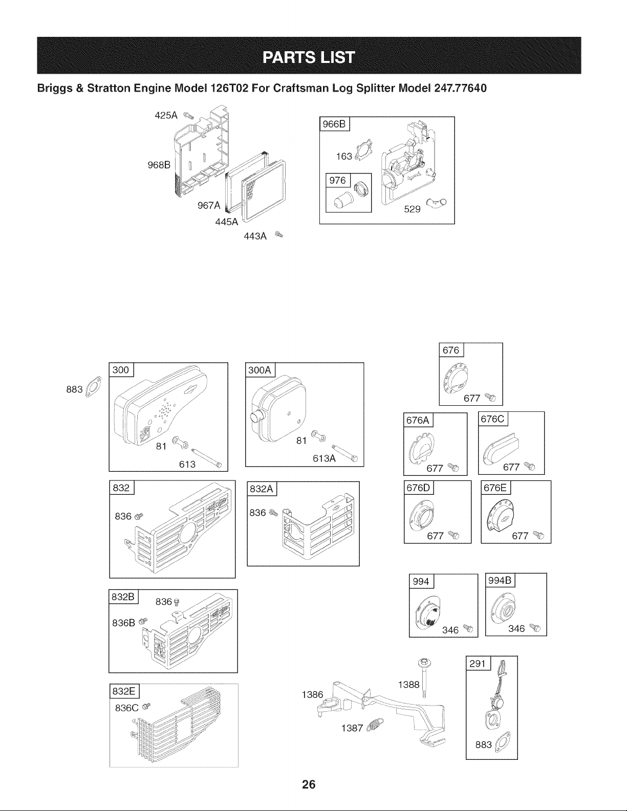
Briggs & Stratton Engine Model 126T02 For Craftsman Log Splitter Model 247.77640
968B
967A
445A
443A _
883
8369_ _
836B_ C_" _/_¢_
B0_
J_G\
613A " ©
|
[ ..... 677 _'_
677 _ 677 _?)
346 _£;
346 _ _"
1388 i
883
26
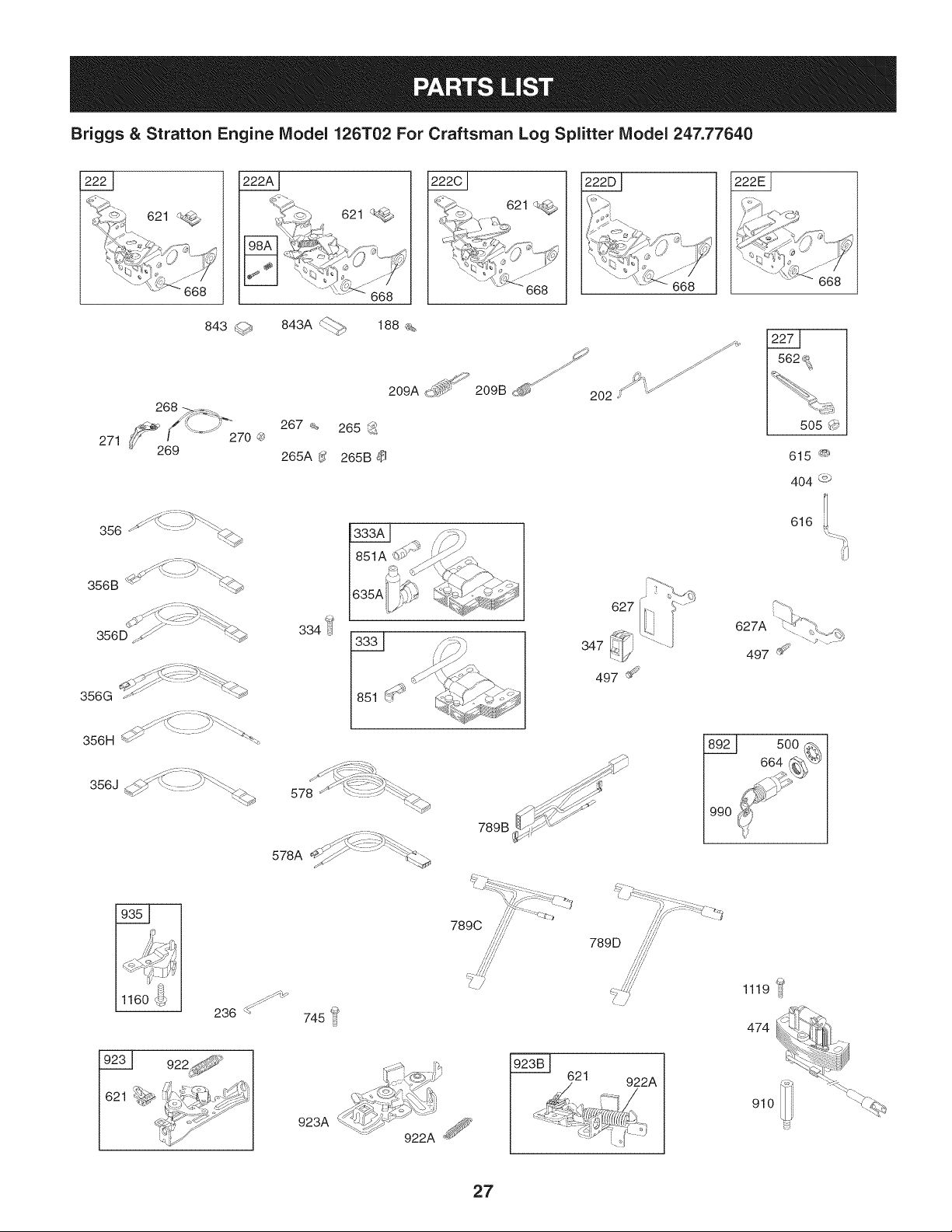
Briggs & Stratton Engine Model 126T02 For Craftsman Log Splitter Model 247.77640
621
621
|
|
843 <_## 843A < ......
268 _ ....
_:-_ __'" 267
271 _6f_9'%=")' 270'_ 265A_'
356 - _.
356B "_ ......
_ !-_:__..
356D ._ '_<_h
356G _ '"_-_
356H _ ....... _'_'%
356J _ "-'_::: ::::_ _.
1160 _U_
188 %
209A _-_ '
265 _:__
265B
J
209B d_ _'_Z_
202
334 _
635A
627
347
497 _
J_ XI .--.%: *:-_
578A _..,¢/ _ _._._
789 B _"'_
789D
745 _
923A
621
922A
616
627A
497 _
500
0
1119 ::4
474
910
27
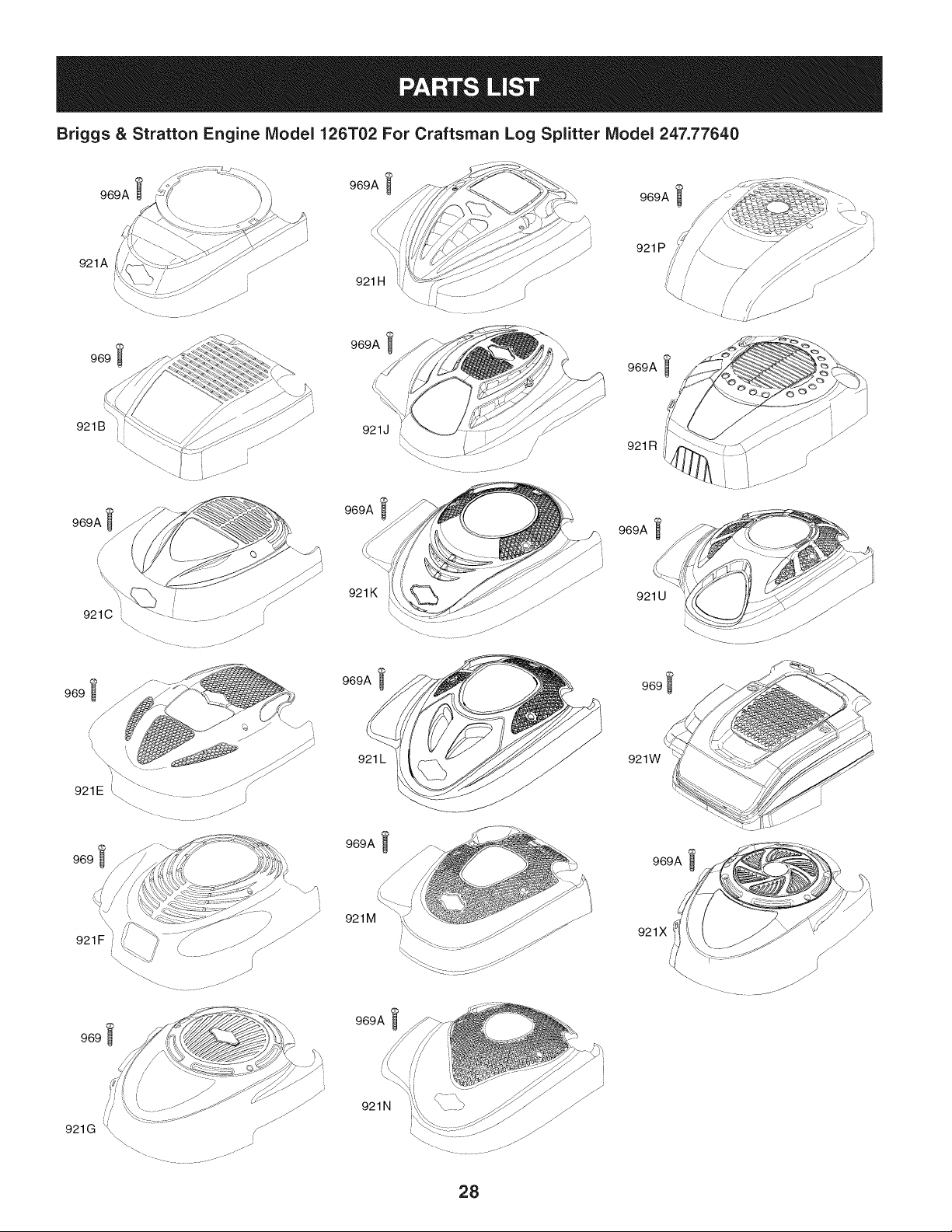
Briggs & Stratton Engine IViodel 126T02 For Craftsman Log Splitter IViodel 247.77640
921A
969
_" //_ 921 P /[
921 H J
F /
969A
969 _l
969A
921J /
969A
921K
969A
921 L
969A
969A _
921 R // ,t-_--_-----__ .//
969A
921 U
969_
921W
969A
921F
969_
921M
969A
921X
/
921N
28
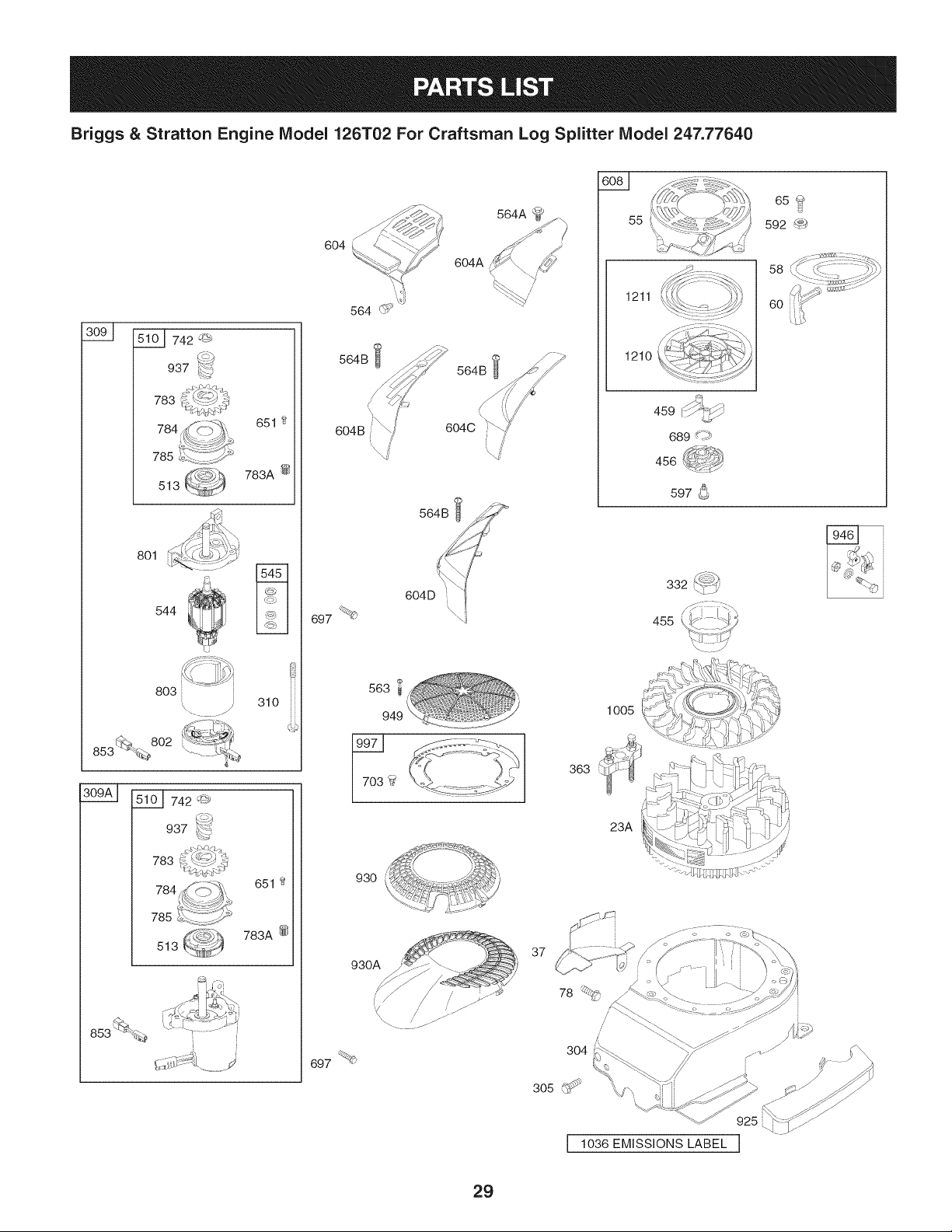
Briggs & Stratton Engine Model 126T02 For Craftsman Log Splitter Model 247.77640
742 _#_;
937
783
651 2
783A @
513
801
544
803 i
310
%
10 I _L _742 '_
937 _-'_
783
651
783A @
513
[
6O4
604A
564B
/
/
6O4B/ /
564B
604C
J
697 %
563
949
930
930A
697 %<_
363
37
78
55
1005
23A
1211
1210
U
459 _j
689 d p>
456
597 _
455
I 1036 EMISSIONS LABEL J
29
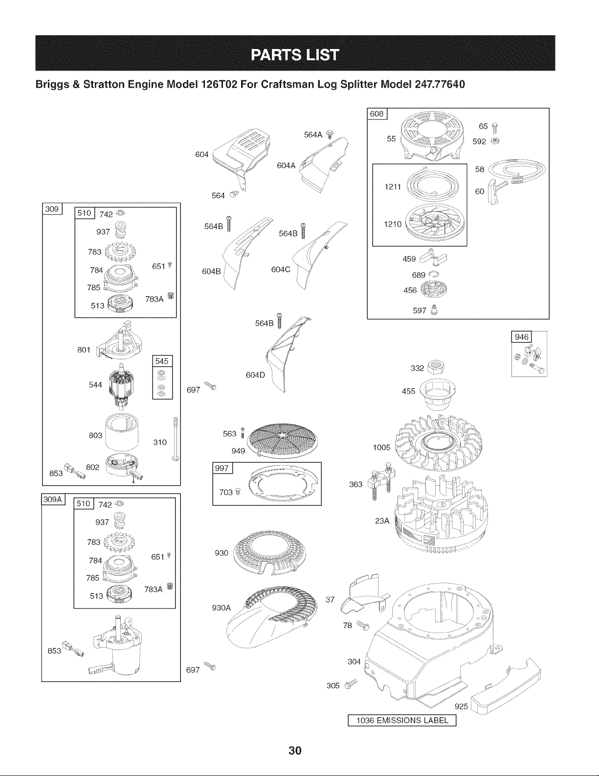
Briggs & Stratton Engine IViodel 126T02 For Craftsman Log Splitter IViodel 247.77640
742 '_r*_
937
783
651 t_
783A @
513
801
544
803
_ 802
853 __. .......
310
651
783A @
513
564 _:_
564B ¢_
604C
564B
55
65?
592 _
1211
1210
58
60
459 L -
, _-
689 _19
f %,
456 J
597 _)
697 _
563
930
363
1005
23A
'\.. J
,'f_. LI2 ,_
930A
697 _b
37
/,
/
3O4
3O

Briggs & Stratton Engine IViodel 126T02 For Craftsman Log Splitter IViodel 247.77640
BS-697322 CylinderAssembly
2 BS-399269 Bushing/SealKit 65
3 BS-299819S Oil Seal 78
4 BS-493279 EngineSump 81
5 BS-691160 CylinderHead 95
7 BS-692249 CylinderHeadGasket 97
8 BS-695250 BreatherAssembly 98A
9 BS-696125 BreatherGasket 104
10 BS-691125 Screw (BreatherAssembly) 108
11 BS-6917811 BreatherTube 108A
12 BS-692232 CrankcaseGasket 109
13 BS-690912 Screw(CylinderHead) 109A
15 BS-691680 Oil DrainPlug 109B
16 BS-691455 Crankshaft 117
20 BS-399781S Oil Seal 117A
22 BS-691092 Screw 117B
23A BS-691992 Flywheel 118
24 BS-222698S FlywheelKey 118A
25 BS-797302 PistonAssembly 118B
26 BS-797304 RingSet 121
27 BS-691588 PistonPin Lock 125
28 BS_298909 PistonPin 125A
29 BS-797306 ConnectingRod 125B
32 BS-691664 Screw 127
32A BS-695759 Screw 130
33 BS-262651S ExhaustValve 130A
34 BS-262652S IntakeValve 133
35 BS-691270 ValveSpring(Intake) 134
36 BS-691270 ValveSpring(Exhaust) 137
37 BS-694086 FlywheelGuard 146
40 BS-692194 ValveRetainer 163
43 BS-691997 Governor/OilSlinger 187
45 BS-690548 ValveTappet 187A
46 BS-691449 Camshaft 188
50A BS-794305 IntakeManifold 190
51 BS-272199S IntakeGasket 202
51A BS-794306 IntakeGasket 209A
54 BS-691650 Screw(IntakeManifold) 217
55 BS-691421 RewindStarterHousing 222
58 BS-697316 Starter Rope
BS-281434S StarterRopeGrip
BS-690837 Screw(RewindStarter)
BS-691108 Screw(FlywheelGuard)
BS-691740 MufflerScrewLock
BS-691636 Screw(ThrottleValve)
BS-493267 ThrottleShaft
BS-493280 Idle SpeedKit
BS-691242 FloatHingePin
BS-691182 ChokeValve
BS-795935 ChokeValve
BS-494218 ChokeShaft
BS-498593 ChokeShaft
BS-795936 ChokeShaft
BS-498978 MainJet
BS-498981 MainJet(Standard)
BS-695042 MainJet(Standard)
BS-497466 MainJet(HighAltitude)
BS-497315 MainJet(HighAltitude)
BS-694975 MainJet(HighAltitude)
BS-498260 CarburetorOverhaulKit
BS-498170 Carburetor(PrimerSystem)
BS-792253 Carburetor(ChokeSystem)
BS-794304 Carburetor(AutochokeSystem)
BS-694468 WelchPlug
BS-696564 ThrottleValve
BS-691203 ThrottleValve
BS-398187
BS-398188
BS-693981
BS-690979
BS-272653
BS-791766
BS-791873
BS-693399
BS-690940
BS-691829
BS-790944
BS-690354
BS-790143
CarburetorFloat
Needle/SeatKit
FloatBowlGasket
TimingKey
AirCleanerGasket
FuelLine(Cutto RequiredLength)
FuelLine(Molded)
Screw(ControlBracket)
Screw(FuelTank)
MechanicalGovernorLink
GovernorSpring
ChokeReturnSpring
ControlBracket(Remote/Manual
Friction)(Primer)
31

Briggs & Stratton Engine IViodel 126T02 For Craftsman Log Splitter IViodel 247.77640
BS-692021 ControlBracket(Remote,ChokeA
Matic,NonCompliance)
222D BS-791128 Control Bracket(FixedSpeed)
222E BS-692982 ControlBracket(ManualFriction,5
PositionManualChoke)
227 BS-690783 GovernorControlLever
231 BS-691636 Screw(ChokeValve)
236 BS-691826 LockoutLink
265 BS-690798 CasingClamp
265A BS-691024 _ CasingClamp
265B BS-692179 CasingClamp
267 BS-691044 Screw (CasingClamp)
268 BS-691025 ControlWireCasing (Cutto Required
_ _ Length)
269 BS-691026 ControlWire(Cut to Required
Length)
270 BS-691027 Nut(ControlWire Casing)
271 BS-691028 ControlLever
276 BS-271716 SealingWasher
287 BS-690940 Screw(DipstickTube)
291 BS-790830 Thermostat
300 BS-692038 Muffler
300A BS-494343S Muffler
304 BS-493294 BlowerHousing
305 BS-691108 Screw(BlowerHousing)
306 BS-690450 CylinderShield
306A BS-790836 CylinderShield
307 BS-690345 Screw(CylinderShield)
309 BS-695550 StarterMotor
310 BS-692327 Bolt(StarterMotor)
332 BS-690662 L Nut (Flywheel)
333 BS-802574 MagnetoArmature
333A BS-793353 MagnetoArmature
334 BS-691061 Screw(MagnetoArmature)
337 759-3338 SparkPlug
346 BS-690661 Screw(SparkArrester)
347 BS-691396 RockerSwitch
356 BS-692390 StopWire
356B BS-693010 StopWire
=
356D BS-496381 StopWire
356G BS-695283 StopWire
BS-690791 StopWire
356J BS-691423 StopWire
358 BS-794307 EngineGasketSet
363 BS-19069 FlywheelPuller
365 BS-691688 Screw(Carburetor)
383 BS-89838S SparkPlugWrench
404 BS-690272 Washer(GovernorCrank)
425A BS-690670 Screw(AirCleanerCover)
443A BS-692523 Screw(AirCleanerPrimerBase)
445A BS-491588S AirCleanerFilterCartridge
455 BS-791960 FlywheelCup
456 BS-692299 PawlFrictionPlate
459 BS-281505S RatchetPlate
474 BS-691991 Alternator
497 BS-690664 Screw(StopSwitchBracket)
500 BS-691086 Washer(Key Switch)
505 BS-691251 Nut(GovernorControl Lever)
510 BS-795093 StarterDrive
513 BS-692358 DriveClutch
523 BS-499621 Dipstick
524 BS-692296 DipstickTubeSeal
525 BS-495265 DipstickTube
529 BS-691923 Grommet
544 BS-690786 StarterArmature
545 BS-492919 WasherSet
562 BS-92613 Bolt(GovernorControlLever)
563 BS-691138 Screw(DebrisGuardScreen)
564 BS-690664 Screw(ControlCover)
564A BS-691142 Screw(ControlCover)
564B BS-698589 Screw(ControlCover)
578 BS-398153 AssemblyWire
578A BS-696031 AssemblyWire
584 BS-697734 BreatherPassageCover
585 BS-691879 BreatherPassageGasket
592 BS-690800 Nut(RewindStarter)
597 BS-691696 Screw(PawlFrictionPlate)
601 BS-791850 HoseClamp
601A BS-691038 HoseClamp
604 BS-691757 ControlCover
604A BS-691344 ControlCover
32

Briggs & Stratton Engine IViodel 126T02 For Craftsman Log Splitter IViodel 247.77640
BS-790703 ControlCover
604C BS-792418 ControlCover 789D
604D BS-793770 ControlCover 801
608 BS-497680 RewindStarter 802
613 BS-691340 Screw(Muffler) 803
613A BS-691653 Screw(Muffler) 832
615 BS-690340 GovernorShaft Retainer 832A
616 BS-698801 GovernorCrank
617 BS-270344 O-RingSeal(IntakeManifold)
621 BS-692310 Stop Switch
627 BS-792565 Stop SwitchBracket 836B
627A BS-793211 Stop SwitchBracket 836C
633 BS-691321 Choke/ThrottleShaft Seal 842
633A BS-693867 Choke/ThrottleShaftSeal 843
635 BS-66538S Spark PlugBoot 843A
635A BS-793351 Spark PlugBoot 847
651 BS-691660 Screw (StarterGearCover) 851
664 BS-691087 Nut(Key Switch) 851A
668 BS-493823 Spacer 853
670 BS-692294 FuelTankSpacer 868
676 BS-396548 MufflerDeflector 869
676A BS-393756 MufflerDeflector 870
676C BS-493871 MufflerDeflector 871
676D BS-497682 MufflerDeflector 883
676E BS-393760 MufflerDeflector 892
677 BS-690661 Screw (MufflerDeflector) 910
684 BS-690345 Screw (BreatherPassageCover) 921A
689 BS-691855 FrictionSpring 921B
692 BS-690572 DetentSpring 921C
697 BS-691127 Screw (DriveCap) 921E
703 BS-696309 Clip 921F
718 BS-690959 LocatingPin 921G
741 BS-795755 TimingGear 921H
742 BS-93941 E-RingRetainer 921J
745 BS-691648 Screw(Brake) 921K
783 BS-691918 PinionGear 921L
783A BS-691269 PinionGear 921M
784 BS-795095 StarterGear Cover 921N
785 BS-692352 StarterCover Gasket 921P
789B BS-792685 WiringHarness 921R
33
BS-796385 WiringHarness
BS-796574 WiringHarness
BS-690782 DriveCap
BS-695267 EndCap
BS-695266 StarterHousing
BS-499034 MufflerGuard
BS-691424 MufflerGuard
832B BS-497683 MufflerGuard
832E BS-793568 MufflerGuard
836 BS-690664 Screw(MufflerGuard)
BS-691147 Screw(MufflerGuard)
BS-790745 Screw(MufflerGuard)
BS-691031 O-RingSeal(DipstickTube)
BS-691884 LeverSleeve(SpeedControl)
BS-691895 LeverSleeve(Choke)
BS-692047 Dipstick/TubeAssembly
BS-493880S SparkPlugTerminal
BS-692424 SparkPlugTerminal
BS-695268 WireAdapter
BS-697338 ValveSeal
BS-691155 ValveSeal (Intake)
BS-690380 ValveSeal (Exhaust)
BS-262001 ValveGuide Bushing(Exhaust)
BS-691881 ExhaustGasket
BS-690646 KeySwitch
BS-691094 Stud(Alternator)
BS-695886 BlowerHousingCover
BS-692931 BlowerHousingCover
BS-695889 BlowerHousingCover
BS-696262 BlowerHousingCover
BS-697343 BlowerHousingCover
BS-790701 BlowerHousingCover
BS-790037 BlowerHousingCover
BS-790036 BlowerHousingCover
BS-699984 BlowerHousingCover
BS-791026 BlowerHousingCover
BS-792652 BlowerHousingCover
BS-792675 BlowerHousingCover
BS-792687 BlowerHousingCover
BS-793771 BlowerHousingCover

Briggs & Stratton Engine IViodel 126T02 For Craftsman Log Splitter IViodel 247.77640
BS-794355 BlowerHousingCover BS-692298 Air CleanerCover
921W BS-796921 BlowerHousingCover 969 BS-690700 Screw(BlowerHousingCover)
921X BS-796706 BIowerHousingCover 969A BS-691138 Screw(BIowerHousingCover)
922 BS-691831 BrakeSpring 970 BS-691669 Screw(AirCleanerPrimerBracket)
922A BS-692135 BrakeSpring 972B BS-699374 FueITank
923 BS-691994 Brake 975 BS-493640 FloatBowl
923A BS-695891 Brake 976 BS-694395 CarburetorPrimer
923 BS-691994 Brake 977 BS-498261 CarburetorGasketSet
923A BS-695891 Brake 990 BS-691959 KeySet
923B BS-796136 Brake 994 BS-398067 SparkArrestor
925 BS-795403 LinkageCover 994B BS-792245 SparkArrestor
930 BS-691919 RewindGuard 997 BS-696310 DebrisShield
930A BS-691345 RewindGuard 1005 BS-691346 FlywheelFan
935 BS-499421 InterlockSwitch 1019 BS-694881 Label Kit
937 BS-691325 StarterSpline 1036 -- EmissionsLable
946 BS-691738 RopeStop 1058 BS-277039 Operator'sManual
949 BS-696306 DebrisScreenGuard 1059 BS-692311 Screw/WasherKit
957B BS-699985 FueITankCap 1095 BS-498528 ValveGasketSet
958 BS-698183 FuelShut OffValve 1119 BS-692979 Screw(Alternator)
966B BS-792040 Air CleanerPrimerBase 1160 BS-690345 Screw(InterlockSwitch)
967A BS-493537S Pre-CleanerFilter 1210 BS-498144 Pulley/SpringAssembly(Pulley)
1211 BS-498144 Pulley/SpringAssembly(Spring)
1319 BS-794467 WarningLabel
1330 BS-270962 RepairManual
1386 BS-790848 AirVane(AutochokeSystem)
1387 BS-790849 AirVaneSpring
1388 BS-790850 Screw(AirVane)
34
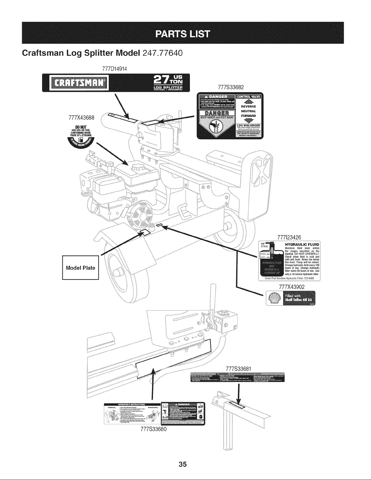
Craftsman Log Splitter Model 247.77640
777D14914
777S33682
777X43688
DONOT
USEEH5ORFUEL
CONTAININGMORE
THAN10% ETHANOL
777123426
HYDRAULIC FLUID I
INaintairl fl.id level witbirl
the ranges specified on the
dipstick.DO NOT OVERFILL!
Cllelk Wllen fltlid is cold and
witll .nN level. Neverrunbelow
this level. Primp wig be r.ineg.
0flier P_rt IE _) r Hy_l_ lie _ilter 723-9405
Changehydra.lie Nuig every100
hour_ of use. Changehydraulic
filterevery 50hours of use. Use
onlya 10 micron kydratgic tilter.
777X43902
777S33681
777S33680
35
Congratulationson makinga smartpurchase.YournewCraftsman@
productis designedandmanufacturedfor yearsof dependableopera-
tion.But likeall products,it may requirerepairfrom time to time.That's
whenhavinga RepairProtectionAgreementcansaveyoumoneyand
aggravation.
Here'swhatthe RepairProtectionAgreement*includes:
* Expert service byour 10,000professionalrepairspecialists
o Unlimitedserviceand no chargefor partsand laboron all
coveredrepairs
o Product replacementupto $1500if yourcoveredproductcan't be
fixed
• Discountof 10%from regularprice of serviceand relatedinstalled
partsnotcoveredby theagreement;also,10%off regularpriceof
preventivemaintenancecheck
• Fast help by phone- we call it RapidResolution- phonesupport
froma Searsrepresentative.Thinkof usas a "talkingowner's
manual."
Onceyou purchasethe Agreement,a simplephonecall is all thatit
takesfor youto scheduleservice.Youcan call anytimedayor night,or
schedulea serviceappointmentonline.
The RepairProtectionAgreementis a risk-freepurchase.If youcancel
for any reasonduringthe productwarrantyperiod,wewill provideafull
refund.Or,a proratedrefundanytimeafterthe productwarrantyperiod
expires.Purchaseyour RepairProtectionAgreementtoday!
Somelimitationsand exclusionsapply. For pricesand additional
informationin the U.S.A.call 1-800-827-6655.
*Coverage in Canadavaries on some items.Forfull details call
Sears Canadaat 1-800-361-6665.
Sears Installation Service
ForSearsprofessionalinstallationof homeappliances,garagedoor
openers,waterheaters,and othermajorhomeitems,in the U.S.A.or
Canadacall 1-800-4-MY-HOME®.
36
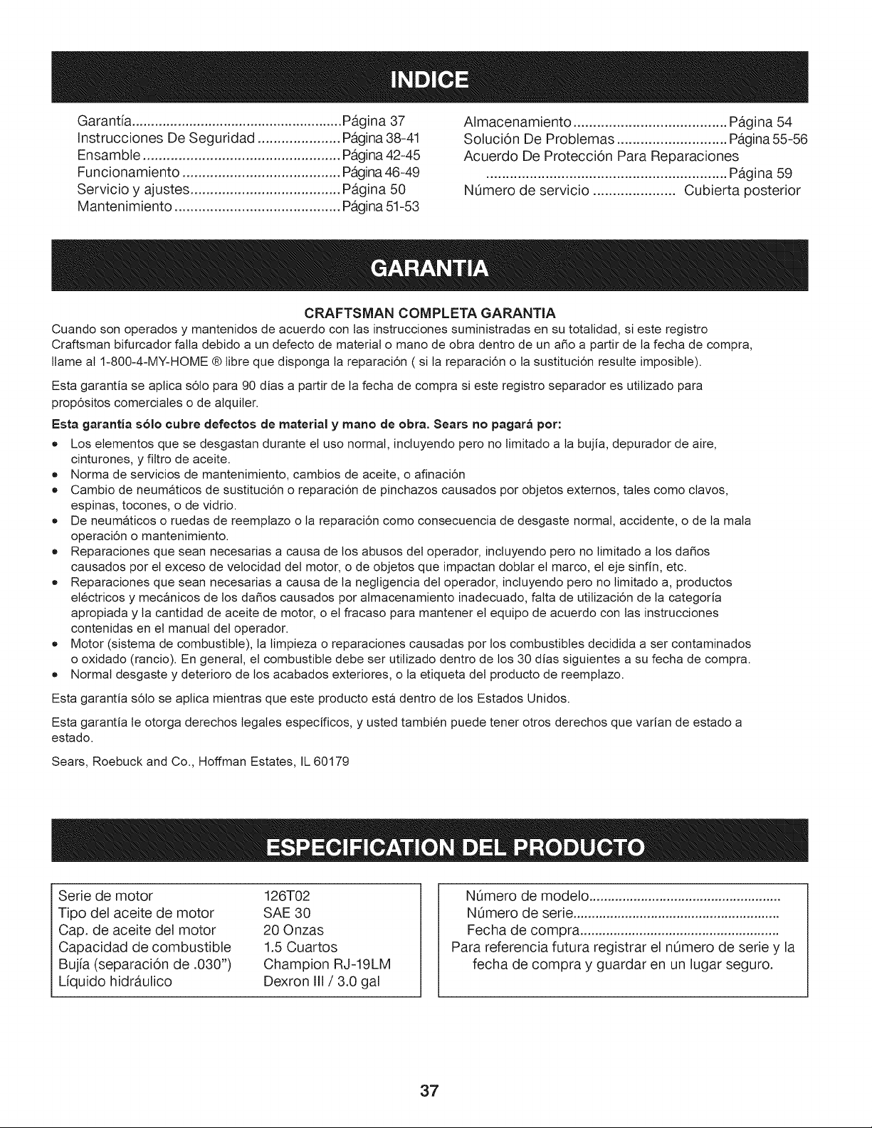
Garantia ....................................................... Pagina 37
Instrucciones De Seguridad ..................... Pagina 38-41
Ensamble .................................................. Pagina 42-45
Funcionamiento ........................................ Pagina 46-49
Servicio y ajustes ...................................... Pagina 50
Mantenimiento .......................................... Pagina 51-53
Almacenamiento ....................................... Pagina 54
Solucion De Problemas ............................ Pagina 55-56
Acuerdo De Protecci6n Para Reparaciones
............................................................. Pagina 59
NOmero de servicio ..................... Cubierta posterior
CRAFTSMAN COMPLETA GARANTIA
Cuando son operados y mantenidos de acuerdo con tas instrucciones suministradas en su totalidad, si este registro
Craftsman bifurcador falla debido a un defecto de material o mano de obra dentro de un a_o a partir de ta fecha de compra,
flame al 1-800-4-MY-HOME ® fibre que disponga la reparaci6n ( si ta reparaci6n o ta sustituci6n resulte imposibte).
Esta garantia se aplica s61o para 90 dias a partir de la fecha de compra si este registro separador es utitizado para
prop6sitos comerciales o de alquiter.
Esta garantia solo cubre defectos de material y mano de obra. Sears no pagara per:
* Los etementos que se desgastan durante et uso normal, incluyendo pero no limitado a la bujia, depurador de aire,
cinturones, y fittro de aceite.
* Norma de servicios de mantenimiento, cambios de aceite, o afinaci6n
* Cambio de neumaticos de sustituci6n o reparaci6n de pinchazos causados por objetos externos, tales como clavos,
espinas, tocones, o de vidrio.
* De neumaticos o ruedas de reemplazo o ta reparaci6n como consecuencia de desgaste normal, accidente, o de la mala
operaci6n o mantenimiento.
* Reparaciones que sean necesarias a causa de los abusos det operador, incluyendo pero no limitado a los da_os
causados por el exceso de vetocidad det motor, o de objetos que impactan doblar et marco, et eje sinfin, etc.
* Reparaciones que sean necesarias a causa de la negligencia det operador, inctuyendo pero no limitado a, productos
etectricos y mecanicos de los da_os causados por almacenamiento inadecuado, falta de utilizaci6n de la categoria
apropiada y la cantidad de aceite de motor, o et fracaso para mantener et equipo de acuerdo con las instrucciones
contenidas en el manual del operador.
* Motor (sistema de combustible), ta limpieza o reparaciones causadas por los combustibles decidida a ser contaminados
o oxidado (rancio). En general, et combustible debe ser utitizado dentro de los 30 dias siguientes a su fecha de compra.
* Normal desgaste y deterioro de los acabados exteriores, o ta etiqueta det producto de reemplazo.
Esta garantia s61o se aptica mientras que este producto esta dentro de los Estados Unidos.
Esta garantia le otorga derechos legales especificos, y usted tambien puede tener otros derechos que varian de estado a
estado.
Sears, Roebuck and Co., Hoffman Estates, IL 60179
Serie de motor
Tipo del aceite de motor
Cap. de aceite del motor
Capacidad de combustible
Bujfa (separaci6n de .030")
Liquido hidraulico
126T02
SAE 30
20 Onzas
1.5 Cuartos
Champion RJ-19LM
Dexron III/3.0 gal
NOmero de modelo ....................................................
NOmero de serie ........................................................
Fecha de compra ......................................................
Para referencia futura registrar el nOmero de serie y la
fecha de compra y guardar en un lugar seguro.
37
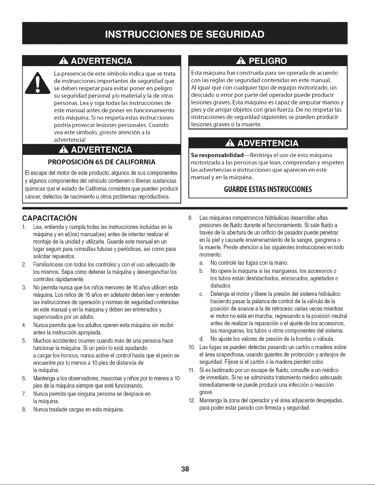
La presencia de este sfmbolo indica que se trata
de instrucciones importantes de seguridad que
se deben respetar para evitar poner en peligro
su seguridad personal y/o material y la de otras
personas. Leay siga todas las instrucciones de
este manual antes de poner en funcionamiento
esta m_quina. Si no respeta estas instrucciones
podrfa provocar lesiones personales. Cuando
vea este sfmbolo, ipreste atenci6n a la
advertencia!
PROPOSICION 65 DE CALIFORNIA
Elescapedel motorde esteproducto,algunosde sus componentes
y algunoscomponentesdel vehiculocontieneno liberansustancias
quimicasqueelestadode Californiaconsideraque puedenproducir
c_ncer,defectosde nacimientou otros problemasreproductivos.
Esta m_quina fue construida para set operada de acuerdo
con las reglas de seguridad contenidas en este manual.
AI igual que con cualquier tipo de equipo motorizado, un
descuido o error pot parte del operador puede producir
lesiones graves. Esta m,iquina es capaz de amputar manos y
pies y de arrojar objetos con gran fuerza. De no respetar las
instrucciones de seguridad siguientes se pueden producir
lesiones graves o la muerte.
Su responsabilidad--Restrinja el uso de esta m_iquina
motorizada alas personas que lean, comprendan y respeten
las advertencias e instrucciones que aparecen en este
manual y en la m_iquina.
GUARDEESTASINSTRUCCIONES
CAPACITACION
1. Lea,entienday cumplatodaslas instruccionesincluidasen la
m_quinayen el(los)manual(es)antes de intentarrealizarel
montajede la unidady utilizarla.Guardeeste manualen un
lugarseguropara consultasfuturasy peri6dicas,asi comopara
solicitarrepuestos.
2. Familiaricesecontodos los controlesy con el usoadecuadode
los mismos.Sepac6modetenerla m_quinay desengancharlos
controlesr_pidamente.
3. No permitanuncaque losniEosmenoresde 16aEosutilicenesta
m_quina.Losni_osde 16a_osenadelantedebenleery entender
las instruccionesde operaci6ny normasdeseguridadcontenidas
enestemanualyen la m_quinay debenserentrenadosy
supervisadosporunadulto.
4. Nuncapermitaque los adultosoperenestam_quinasin recibir
antesla instrucci6napropiada.
5. Muchosaccidentesocurrencuandom_s de una personahace
funcionarla m_quina.Si unpe6nIo est_ ayudando
acargar lostroncos,nuncaactiveel controlhastaqueel pe6nse
encuentreporIo menosa 10piesde distanciade
la m_quina.
6. Mantengaa losobservadores,mascotasy ni_ospor Iomenosa 10
piesdelam_quinasiempreque est_funcionando.
7. Nuncapermitaque ningunapersonase desplaceen
la m_quina.
8. Nuncatrasladecargasen esta m&quina.
9. Lasm&quinasrompetroncoshidr&ulicasdesarrollanaltas
presionesde fluidoduranteel funcionamiento.Sisalefluido a
trav_sdela aberturade unorificiode pasadorpuedepenetrar
en la piel y causarleenvenenamientode la sangre,gangrenao
la muerte.Presteatenci6nalas siguientesinstruccionesen todo
momento:
a. Nocontrolelas fugascon la mano.
b. Noopere la m&quinasi las mangueras,los accesorioso
los tubos est&ndeshilachados,enroscados,agrietadoso
daSados.
c. Detengael motory liberelapresi6ndelsistemahidr&ulico
haciendopasarla palancade controldela valvulade la
posici6nde avancea la de retrocesovariasvecesmientras
el motorno est&en marcha;regresandoa laposici6nneutral
antesde realizarlareparaci6no el ajustede los accesorios,
las mangueras,los tubos u otros componentesdel sistema.
d. Noajuste losvaloresde presi6nde la bombao v&lvula.
10. Lasfugas se puedendetectarpasandouncart6no maderasobre
el &reasospechosa,usandoguantesde protecci6ny anteojosde
seguridad.Fijesesi el cart6no la maderapierdencolor.
11. Si es lastimadoporunescapede fluido,consultea un m_dico
de inmediato.Si nose administratratamientom_dicoadecuado
inmediatamentese puede producirunainfecci6no reacci6n
grave.
12. Mantengala zonadeloperadory el &reaadyacentedespejadas,
parapoderestarparadocon firmezay seguridad.
38
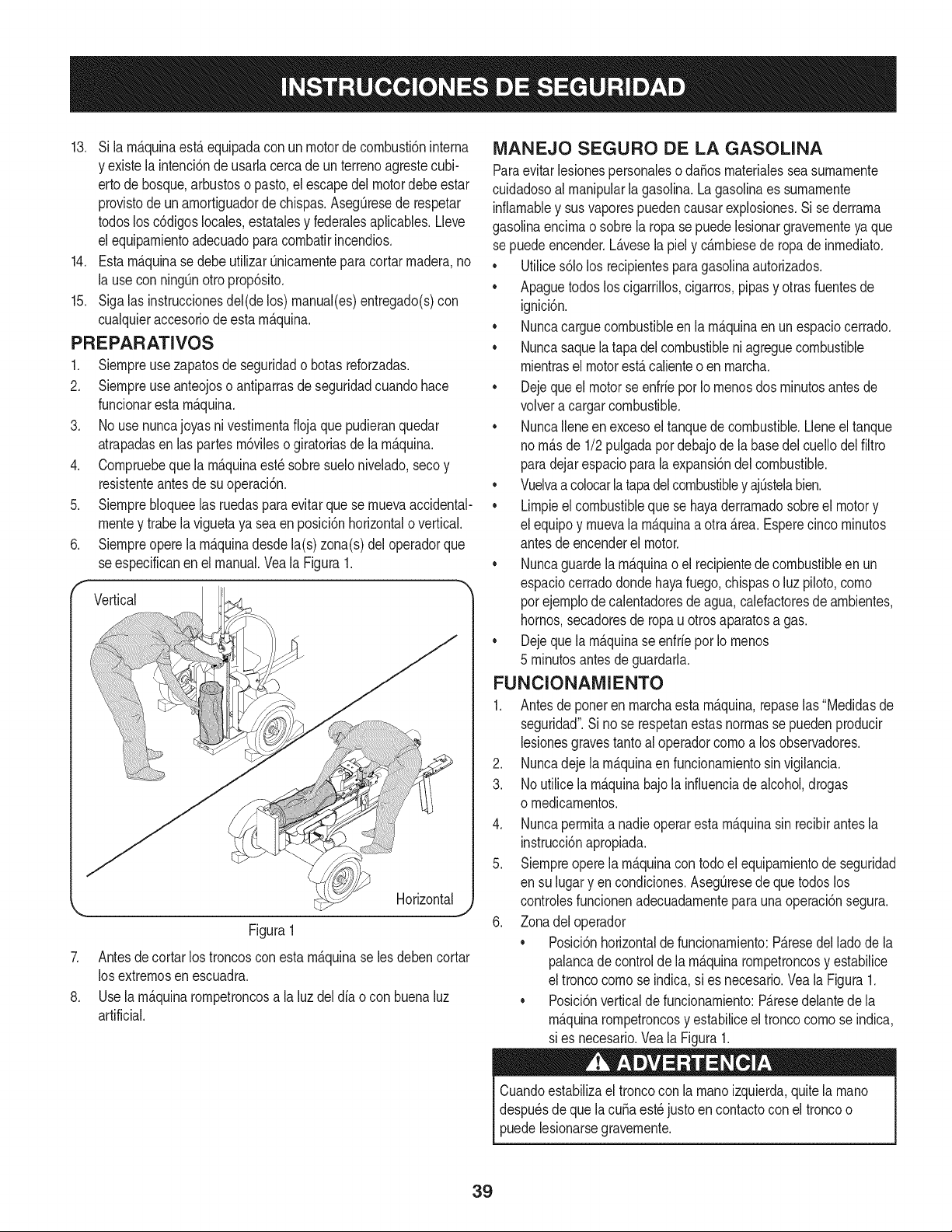
13. Si larn_.quinaest,. equipadacon un motordecornbusti6ninterna
y existela intenci6nde usarlacercade unterrenoagrestecubi-
ertode bosque,arbustoso pasto,el escapedel motordebe estar
provistode unarnortiguadorde chispas.AsegQresede respetar
todoslos c6digoslocales,estatalesy federalesaplicables.Lleve
el equiparnientoadecuadopara cornbatirincendios.
14. Esta rn_.quinasedebeutilizarQnicarnenteparacortarrnadera,no
la usecon ningQnotroprop6sito.
15. Siga las instruccionesdel(delos) rnanual(es)entregado(s)con
cualquieraccesoriodeestarn_.quina.
PREPARATIVOS
1. Siernpreusezapatosde seguridado botasreforzadas.
2. Siernpreuseanteojoso antiparrasdeseguridadcuandohace
funcionarestarn_.quina.
3. No usenuncajoyas nivestirnentafioja que pudieranquedar
atrapadasen laspartesrn6vileso giratoriasde la rn_.quina.
4. Cornpruebeque larn_.quinaest_sobresuelonivelado,seco y
resistenteantesde suoperaci6n.
5. Siernprebloqueelas ruedaspara evitarque sernuevaaccidental-
rnentey trabe la viguetaya sea en posici6nhorizontalo vertical.
6. Siernpreopere la rn_.quinadesdela(s) zona(s)del operadorque
se especificanen el manual.Veala Figura1.
_ Vertical "]
Horizontal
Figura1
7. Antesde cortar los troncosconesta rn_.quinase les debencortar
los extrernosenescuadra.
8. Use la rn_.quinarornpetroncosa la luz deldiao con buenaluz
artificial.
NIANEJO SEGURO DE LA GASOLINA
Paraevitarlesionespersonalesoda_os rnaterialesseasurnarnente
cuidadosoal rnanipularla gasolina.La gasolinaes surnarnente
inflarnabley susvaporespuedencausarexplosiones.Sise derrarna
gasolinaencirnao sobrela ropa se puedelesionargravernenteya que
sepuedeencender.L_.vesela piely c_.rnbiesede ropade inrnediato.
• Utilices61olos recipientesparagasolinaautorizados.
• Apaguetodosloscigarrillos,cigarros,pipasy otrasfuentesde
ignlclon.
• Nuncacarguecombustibleenla rn_.quinaenun espaciocerrado.
• Nuncasaquelatapadel combustibleniagreguecombustible
rnientrasel motorest,. calienteo en rnarcha.
• Dejequeelmotorse enfriepor Io rnenosdosrninutosantesde
volvera cargarcombustible.
• NuncaIleneen excesoel tanquede combustible.Lleneel tanque
norn_.sde 1/2pulgadapordebajode la basedelcuellodelfiltro
paradejarespacioparalaexpansi6ndelcombustible.
• Vuelvaacolocarlatapadelcombustibley ajQstelabien.
• Lirnpieel combustibleque se hayaderrarnadosobreel motory
el equipoy rnuevala rn_.quinaa otra_.rea.Esperecincorninutos
antesdeencenderel motor.
• Nuncaguardelarn_.quinao el recipientede combustibleen un
espaciocerradodondehayafuego,chispaso luz piloto,corno
porejernplodecalentadoresde agua,calefactoresde arnbientes,
hornos,secadoresde ropau otrosaparatosa gas.
• Dejequelarn_.quinase enfriepor Iornenos
5 rninutosantes de guardarla.
FUNCIONAIVilENTO
1. Antes de poneren rnarchaesta rn&quina,repaselas"Medidasde
seguridad".Sino se respetanestasnorrnasse puedenproducir
lesionesgravestantoal operadorcornoa los observadores.
2. Nuncadeje larn_.quinaen funcionarnientosin vigilancia.
3. Noutilice la rn_.quinabajola infiuenciade alcohol,drogas
o rnedicarnentos.
4. Nuncaperrnitaa nadieoperarestarn_.quinasin recibirantesla
instrucci6napropiada.
5. Siernpreopere la rn_.quinacon todoel equiparnientode seguridad
en su lugary encondiciones.AsegQresede quetodoslos
controlesfuncionenadecuadarnenteparaunaoperaci6nsegura.
6. Zonadeloperador
• Posici6nhorizontaldefuncionarniento:P_.resedel ladodela
palancade controlde la rn_.quinarornpetroncosy estabilice
el troncocornose indica,si es necesario.Veala Figura1.
• Posici6nverticalde funcionarniento:P_.resedelantede la
rn_.quinarornpetroncosy estabiliceel troncocornose indica,
sies necesario.Vea la Figura1.
Cuandoestabilizael troncocon la rnanoizquierda,quitela rnano
despu_sde quela cuSaest_justoen contactocon el troncoo
puedelesionarsegravernente.
39
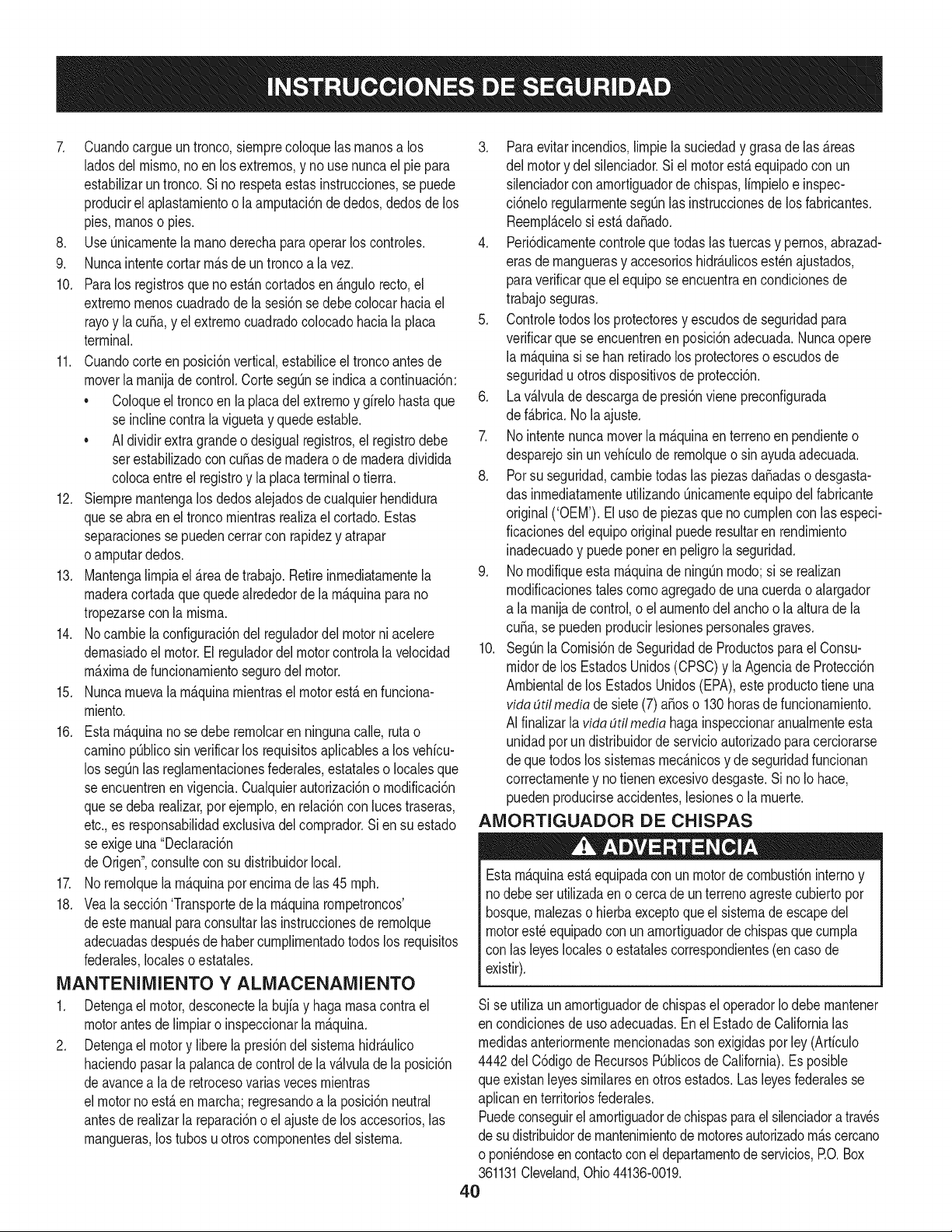
7. Cuandocargueuntronco,siernprecoloquelas rnanosa los
ladosdel misrno,noen los extrernos,y nouse nuncael pie para
estabilizarun tronco.Si no respetaestasinstrucciones,se puede
producirel aplastarnientoo laarnputaci6nde dedos,dedosdelos
pies,rnanoso pies.
8. Use Qnicarnentela rnanoderechaparaoperarloscontroles.
9. Nuncaintentecortar rn_.sde untroncoa lavez.
10. Paralos registrosqueno est_.ncortadosen _.ngulorecto,el
extrernornenoscuadradode lasesi6nse debecolocarhaciael
rayoy la curia,y el extrernocuadradocolocadohaciala placa
terminal.
11. Cuandocorteen posici6nvertical,estabiliceel troncoantesde
moverla rnanijade control.Corte segQnse indicaa continuaci6n:
• Coloqueel troncoen la placadel extrernoy girelo hastaque
se inclinecontrala viguetay quedeestable.
AIdividirextragrandeo desigualregistros,el registrodebe
setestabilizadoconcutlasde rnaderao de rnaderadividida
colocaentreel registroy la placaterminalotierra.
12. Siernprernantengalos dedosalejadosdecualquierhendidura
quese abra en el troncornientrasrealizael cortado.Estas
separacionessepuedencerrarcon rapidezy atrapar
oarnputardedos.
13. Mantengalirnpiael_.reade trabajo.Retireinrnediatarnentela
rnaderacortadaquequedealrededordela rn_.quinaparano
tropezarsecon la rnisrna.
14. Nocarnbiela configuraci6ndel reguladordel motorni acelere
dernasiadoel motor.Elreguladordel motorcontrolalavelocidad
rn_.xirnadefuncionarnientosegurodel motor.
15. Nuncarnuevala rn_.quinarnientrasel motorest,.en funciona-
rniento.
16. Esta rn_.quinanose debe rernolcaren ningunacalle, rutao
carninopOblicosinverificarlos requisitosaplicablesa los vehicu-
los segQnlas reglarnentacionesfederales,estataleso localesque
se encuentrenen vigencia.Cualquierautorizaci6no rnodificaci6n
quese deba realizar,por ejernplo,en relaci6ncon lucestraseras,
etc.,es responsabilidadexclusivadelcornprador.Si ensu estado
se exigeuna "Declaraci6n
de Origen",consultecon su distribuidorlocal.
17. No rernolquelarn_.quinaporencirnade las 45 rnph.
18. Vea la secci6n'Transportede la rn_.quinarornpetroncos'
deestemanualparaconsultarlas instruccionesde rernolque
adecuadasdespu_sde habercurnplirnentadotodos los requisitos
federales,localeso estatales.
MANTENIMIENTO Y ALIVlACENANIIENTO
1. Detengael motor,desconectela bujiay hagarnasacontrael
motorantesde lirnpiaroinspeccionarla rn_.quina.
2. Detengael motory liberela presi6ndel sisternahidr_.ulico
haciendopasarla palancade controlde lav_.lvulade la posici6n
deavancea lade retrocesovariasvecesrnientras
el motornoest,.en rnarcha;regresandoa la posici6nneutral
antesde realizarla reparaci6no elajustedelos accesorios,las
rnangueras,los tubosu otroscornponentesdel sisterna.
3. Paraevitarincendios,lirnpiela suciedady grasade las _.reas
del motory del silenciador.Siel motorest,.equipadocon un
silenciadorcon arnortiguadorde chispas,lirnpieloe inspec-
ci6neloregularrnentesegQnlas instruccionesde losfabricantes.
Reernpl_.celosi est,.dafiado.
4. Peri6dicarnentecontroleque todas lastuercasy pernos,abrazad-
eras de rnanguerasy accesorioshidr_.ulicosest_najustados,
paraverificarque el equipose encuentraen condicionesde
trabajoseguras.
5. Controletodos losprotectoresy escudosde seguridadpara
verificarque se encuentrenen posici6nadecuada.Nuncaopere
la rn_.quinasi se han retiradolosprotectoreso escudosde
seguridadu otrosdispositivosde protecci6n.
6. La v_.lvuladedescargadepresi6nvienepreconfigurada
de f_.brica.Nola ajuste.
7. Nointentenuncamoverla rn_.quinaen terrenoen pendienteo
desparejosin unvehiculode rernolqueo sin ayudaadecuada.
8. Potsu seguridad,carnbietodas las piezasdafiadasodesgasta-
das inrnediatarnenteutilizandoQnicarnenteequipodel fabricante
original('OEM'). El uso de piezasque no curnplencon las especi-
ficacionesdelequipooriginalpuederesultaren rendirniento
inadecuadoy puedeponer en peligrola seguridad.
9. Nornodifiqueesta rn_.quinade ning_nrnodo;si se realizan
rnodificacionestalescornoagregadode unacuerdao alargador
a la rnanijade control,o el aurnentodel anchoo la alturadela
curia,se puedenproducirlesionespersonalesgraves.
10. SegOnla Cornisi6nde Seguridadde Productosparael Consu-
rnidorde los EstadosUnidos(CPSC)y la Agenciade Protecci6n
Arnbientalde los EstadosUnidos(EPA),este productotieneuna
vida dtil mediade siete(7) afios o 130horasde funcionarniento.
AI finalizarla vida dtflmediahagainspeccionaranualrnenteesta
unidadporundistribuidorde servicioautorizadoparacerciorarse
de quetodoslossisternasrnec_.nicosy de seguridadfuncionan
correctarnentey notienenexcesivodesgaste.SinoIo hace,
puedenproducirseaccidentes,lesioneso la rnuerte.
AMORTIGUADOR DE CHISPAS
Estarn_.quinaest,. equipadacon unmotorde cornbusti6ninternoy
nodebeser utilizadaen o cercade unterrenoagrestecubiertopor
bosque,rnalezaso hierbaexceptoqueelsisternadeescapedel
motorest_equipadocon unarnortiguadorde chispasquecurnpla
con lasleyeslocaleso estatalescorrespondientes(encasode
existir).
Si se utilizaunarnortiguadorde chispasel operadorIo debernantener
en condicionesde usoadecuadas.Enel Estadode Californialas
rnedidasanteriorrnenternencionadassonexigidaspor Icy (Arficulo
4442del C6digode RecursosPOblicosde California).Esposible
queexistanleyessirnilaresenotrosestados.Lasleyesfederalesse
aplicanenterritoriosfederales.
Puedeconseguirel arnortiguadordechispasparael silenciadoratraves
de sudistribuidorde rnantenirnientode rnotoresautorizadorn_.scercano
o poni_ndoseencontactoconel departarnentodeservicios,RO. Box
361131Cleveland,Ohio44136-0019.
40
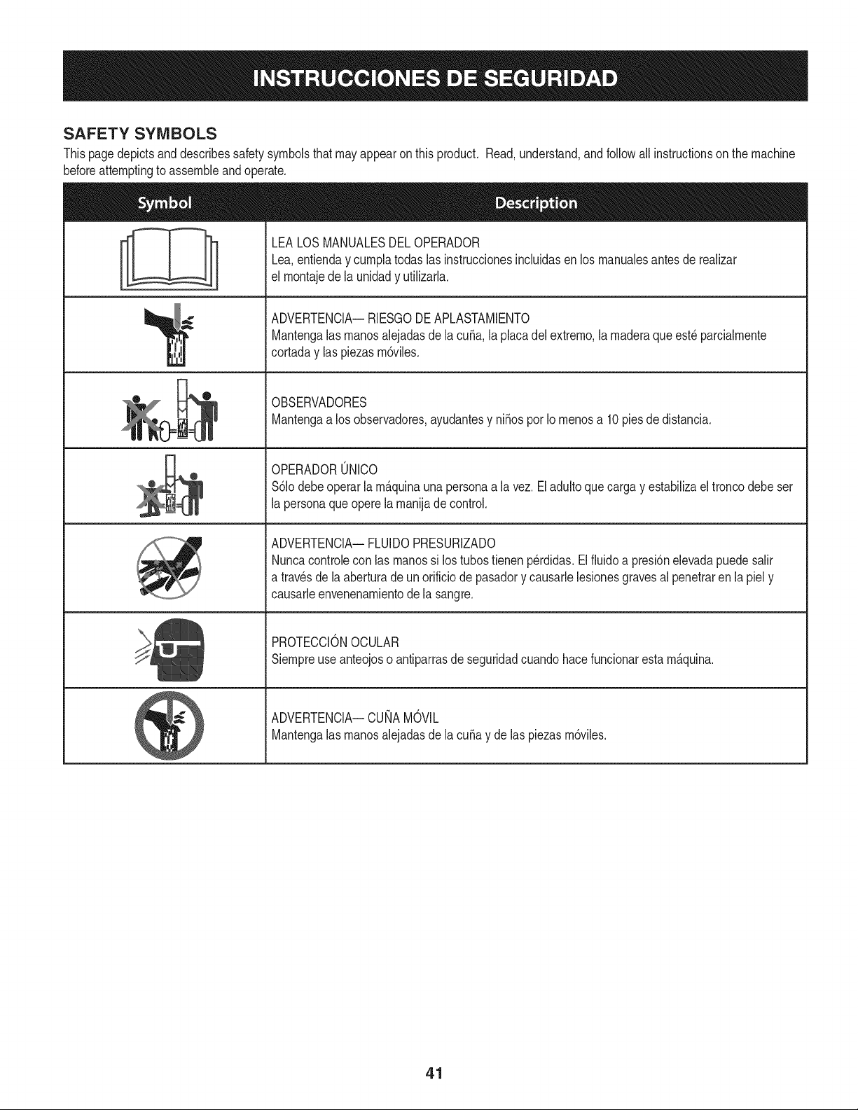
SAFETY SYMBOLS
Thispagedepictsanddescribessafety symbolsthatmayappearonthis product. Read,understand,and follow all instructionson the machine
beforeattemptingto assembleand operate.
LEALOSMANUALESDELOPERADOR
Lea,entienday curnplatodas las instruccionesincluidasen losrnanualesantesderealizar
el rnontajedela unidady utilizarla.
ADVERTENCIA--RIESGODEAPLASTAMIENTO
Mantengalasrnanosalejadasde lacuSa,la placadel extrerno,larnaderaqueest_parcialrnente
cortaday las piezasrn6viles.
OBSERVADORES
Mantengaa los observadores,ayudantesy niSosporIornenosa 10piesdedistancia.
OPERADORONICO
%1odebeoperarla rn_.quinaunapersonaa la vez.Eladultoquecargay estabilizael troncodebeser
la personaqueoperelarnanijadecontrol.
ADVERTENCIA--FLUlDOPRESURIZADO
Nuncacontrolecon las rnanossi los tubostienen perdidas.Elfiuidoa presi6nelevadapuedesalir
a travesdela aberturade unorificiode pasadory causarlelesionesgravesal penetraren lapiely
causarleenvenenarnientodela sangre.
PROTECCIONOCULAR
Siernpreuseanteojoso antiparrasde seguridadcuandohacefuncionarestarn_.quina.
ADVERTENCIA--CUNAMOVIL
Mantengalasrnanosalejadasde lacuba y de las piezasrn6viles.
41
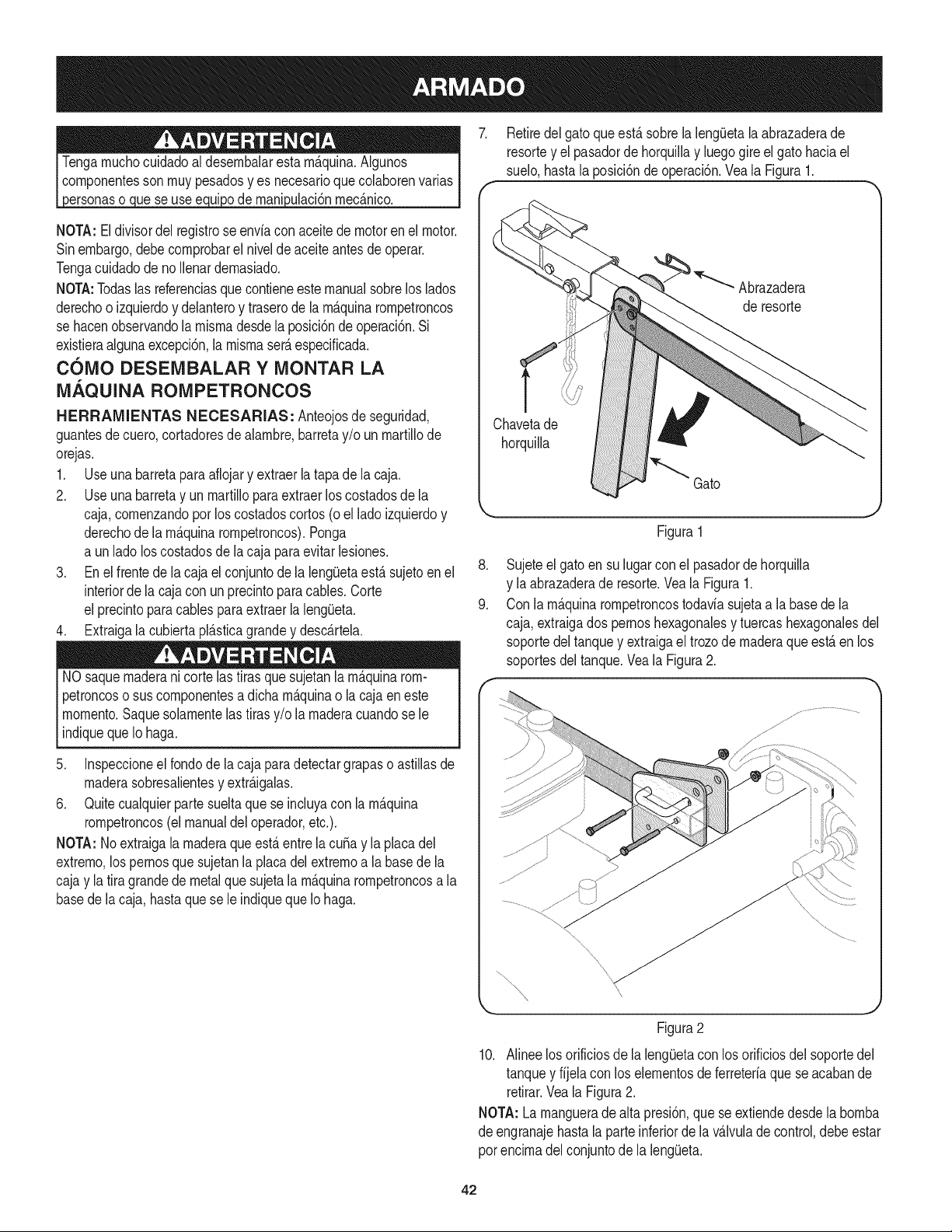
NOTA: Eldivisor del registrose enviacon aceitede motorenel motor.
Sinembargo,debecornprobarel nivelde aceiteantesdeoperar.
Tengacuidadode noIlenardernasiado.
NOTA:Todaslas referenciasquecontieneestemanualsobrelos lados
derechoo izquierdoy delanteroy traserode larn_.quinarornpetroncos
se hacenobservandolarnisrnades@la posici6nde operaci6n.Si
existieraalgunaexcepci6n,la rnisrnaser_.especificada.
COMO DESEMBALAR Y MONTAR LA
MAQUINA ROMPETRONCOS
H ERRAMIENTAS NECESARIAS: Anteojosde seguridad,
guantesde cuero,cortadoresde alarnbre,barretay/o unrnartillode
orejas.
1. Use una barretaparaafiojary extraerla tapade lacaja.
2. Use una barretay unrnartillopara extraerlos costadosde la
caja,cornenzandoporloscostadoscortos(o elladoizquierdoy
derechode larn_.quinarornpetroncos).Ponga
a unladolos costadosde lacaja paraevitarlesiones.
3. En el frentede lacaja elconjuntodela lengOetaest&sujetoenel
interiorde la cajacon unprecintoparacables.Corte
el precintopara cablespara extraerla leng(Jeta.
4. Extraigala cubbrta pl&sticagrandey desc&rtela.
NOsaquernaderani cortelas tirasquesujetanlarn&quinarom-
petroncoso suscornponentesa dicharn_.quinao la cajaeneste
rnornento.Saquesolarnentelas tirasy/o larnaderacuandose le
indiquequeIo haga.
5. Inspeccioneel rondode lacaja paradetectargrapaso astillasde
rnaderasobresalientesy extr_.igalas.
6. Quitecualquierpartesueltaque se incluyacon la rn_.quina
rornpetroncos(el manualdeloperador,etc.).
NOTA: Noextraigala rnaderaqueest,.entre la cuba y la placadel
extrerno,los pernosque sujetanlaplacadel extrernoa labasede la
cajay latira grandede metalquesujetalarn_.quinarornpetroncosa la
basede lacaja,hastaquese leindiquequeIo haga.
,
9.
Retiredel gatoqueest,.sobrela leng_Jetala abrazaderade
resortey el pasadorde horquillay luegogire elgato haciael
suelo,hastala posici6ndeoperaci6n.Vea la Figura1.
Abrazadera
de resorte
Chavetade
horquilla
Gato
Figura1
Sujeteel gatoen sulugar conel pasadorde horquilla
y laabrazaderade resorte.Vea la Figura1.
Con la rn_.quinarornpetroncostodaviasujetaa labasede la
caja,extraigados pernoshexagonalesy tuercashexagonalesdel
soportedel tanquey extraigael trozode rnaderaque est&en los
soportesdeltanque.Veala Figura2.
Figura2
10. Alinee losorificiosde laleng_Jetacon los orificiosdel soportedel
tanquey fijela con los elernentosdeferreteriaquese acabande
retirar.Veala Figura2.
NOTA: La rnanguerade alta presi6n,que seextiendedesdela bornba
de engranajehasta la parteinferiorde la v_.lvuladecontrol,debeestar
porencirnadel conjuntode la bng(Jeta.
42
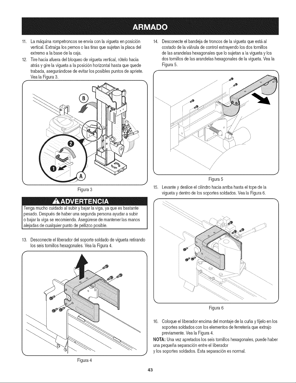
11. La rn_.quinarornpetroncosse envfacon la viguetaenposici6n
vertical.Extraigalos pernoso las tirasquesujetanlaplacadel
extrernoa la basede la caja.
12. Tirehaciaafueradel bloqueode viguetavertical,r6telohacia
atr_.sy girelaviguetaa la posici6nhorizontalhastaquequede
trabada,asegur_.ndosede evitarlos posiblespuntosde apriete.
Veala Figura3.
Figura3
Tengarnuchocuidadoal subiry bajarla viga,ya quees bastante
pesado.Despu_sde haberunasegundapersonaayudara subir
o bajarla vigase recornienda.AsegQresede rnantenerlasrnanos
alejadasdecualquierpuntode pellizcoposible.
13. Desconecteel liberadordel soportesoldadode vigueta retirando
los seis tornilloshexagonales.Veala Figura4.
14.
Desconecteel bandejadetroncosde la viguetaque est,. al
costadodela v_.lvuladecontrolextrayendolosdos tornillos
de las arandelashexagonalesque Io sujetana la viguetay los
dos tornillosde las arandelashexagonalesde la vigueta.Vea la
Figura5.
15.
Figura5
Levantey desliceel cilindrohaciaarriba hastael topede la
viguetay dentrode los soportessoldados.Veala Figura6.
Figura4
Figura6
16. Coloqueel liberadorencirnadelrnontajede la cuSay fijelo en los
soportessoldadoscon loselernentosdeferreteriaqueextrajo
previarnente.Vea la Figura4.
NOTA:Unavezapretadoslos seistornilloshexagonales,puedehaber
unapequeSaseparaci6nentreelliberador
y los soportessoldados.Estaseparaci6nes normal.
43
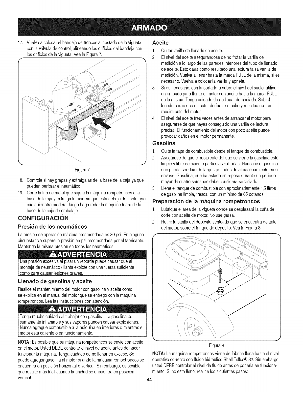
17. Vuelvaa colocarel bandejade troncosal costadode lavigueta Aceite
con la vAIvulade control,alineandolos orificiosdel bandejacon
los orificiosde lavigueta.Veala Figura7.
Figura7
18. Controlesi haygrapasy extrAigalasde la basedela cajaya que
puedenperforarel neurnAtico.
19. Corte la tira de metalquesujetalarnAquinarornpetroncosa la
basede laajay extraigala rnaderaque estAdebajodelmotory/o
cualquierotrarnadera,luegohagarodarlarnAquinafuerade la
basede lacaja deernbalaje.
CONFIGURACI6N
Presi6n de los neurnaticos
La presi6ndeoperaci6nmaximarecornendadaes 30 psi.Enninguna
circunstanciasuperela presi6nen psi recornendadapor el fabricante.
Mantengala rnisrnapresi6nen todoslosneurnAticos.
causarlesiones raves.
Llenado de gasolina y aceite
Realiceel rnantenirnientodel motorcon gasoNnay aceite corno
se expNcaen el manualdel motorquese entreg6con la rnAquina
rornpetroncos.Lealas instruccionesconatenci6n.
Tengarnuchocuidadoal trabajarcon gasolina.LagasoNnaes
sumarnenteinfiarnabley susvaporespuedencausarexplosiones.
I Nuncaagreguecombustiblea la rnAquinaen interioreso rnientrasel
l motorestAcalienteoen funcionarniento.
NOTA: Esposibleque su rnAquinarornpetroncosseenvfecon aceite
enel motor.UstedDEBEcontrolarel niveldeaceiteantesdehacer
funcionarla rnAquina.Tengacuidadodeno Nenarenexceso.Se
puedeagregargasoNnaal motorcuandola rnAquinarornpetroncosse
encuentraen posici6nhorizontalo vertical.Sinembargo,es posible
queresulternAsfAcilcuandola unidadse encuentraen posici6n
vertical.
1. Quitarvarillade Ilenadode aceite.
2. El niveldel aceiteasegurandosede nofrotarlavarillade
rnedici6na Io largode las paredesinterioresdeltubo de Ilenado
de aceite.Estodarfacornoresultadouna lecturafalsa varillade
rnedici6n.Vuelvaa Ilenarhastala rnarcaFULLde la rnisrna,si es
necesario.Vuelvaa colocarla varillay apriete.
3. Si es necesario,con la cortadorasobreel niveldel suelo,utilice
un ernbudopara Ilenarel motorcon aceitehastala rnarcaFULL
de la rnisrna.Tengacuidadode noIlenardernasiado.Sobrel-
lenadoharAnqueel motordefurnarrnuchoy resultarAenun
rendirnientodelmotor.
4. El niveldel aceitetres vecesantes de arrancarel motorpara
asegurarsedeque hayasconseguidounavarillade lectura
precisa.Elfuncionarnientodelmotorcon pocoaceite puede
provocarda_osen el motorperrnanente.
Gasolina
1. Quite latapade combustibledesdeel tanquedecombustible.
2. AsegQresede que el recipientedel quese vierte la gasolinaest_
lirnpioy librede 6xidoo partfculasextra,as. Nuncausegasolina
que puedeserdurode largosperfodosde alrnacenarnientoen su
envase.Gasolina,que haestadoen reposoduranteun perfodo
mayorde cuatrosernanasdebeconsiderarseviciado.
3. Lleneel tanquede combustiblecon aproxirnadarnente1,5litros
de gasolinalirnpia,fresca,con un rnfnirnode85 octanos.
Preparaci6n de la rnaquina rornpetroncos
1. Lubriqueel Areade laviguetadondese desplazarAla cuba de
cortecon aceitede motor.No usegrasa.
2. Retirela varilladel dep6sitoventeadaque se encuentradelante
del motor,sobreeltanquededep6sito.Vea la Figura8.
\
Figura8
NOTA: La rnAquinarornpetroncosvienede fAbricaIlenahastael nivel
operativocorrectoconfluido hidrAulicoShell Tellus®32. Sinembargo,
ustedDEBEcontrolarel niveldefluidoantesdeponerlaenfunciona-
rniento.SinoestAIleno,realicelos siguientespasos:
44
Granpartedel liquidooriginalseha desplazadoen el cilindroy los
tubos.AsegOresede volvera Ilenarel dep6sitoparaevitarquese
dafie labornbahidr_.ulica.
3. Controleel nivelde liquidocon lavarillade nivel.Veala Figura8.
No Ileneel dep6sitoenexceso.
NOTA:Entrelos fluidosaprobadosse encuentranfiuidohidr_.ulico
ShellTellus®32, fluidopara transrnisionesautorn_.ticasDexron®III
/ Mercon®,aceitehidr_.ulicoPro-SelectTM AW-32o aceitehidr_.ulico
32gradodeviscosidadIOWAW-lSO.No se recorniendarnezclarlos
fluidos,para Ilenarhastacornpletareltanquededep6sitodurantela
configuraci6ninicial debeusar Onicarnenteelfluidohidr_.ulicoShell
Tellus®32.
4. Vuelvaa colocarla varillade nivelventeaday apri_telabienhasta
queel topede las roscasquedeal ras del topedel tubo.
5. Desconectela bujiay cebela bornbatirandodel arrancadorde
retrocesohastael rn_.xirno.Repitaeste pasoaproxirnadarnente
10veces.
6. Vuelvaa conectarel cablede labujiay arranqueelmotorseg_n
las instruccionesdel manualdeloperadordelmotor.
7. Use la rnanijadecontrolparaengancharla cura en la posici6n
deextensi6nmaxima.Luegoretraigala cura.
8. Vuelvaa Ilenarel tanquesegQnIo especificadoenla varillade
nivelde sernecesario.
NOTA:Lafaltade Ilenadodeltanqueanulala garantiade
la rn_.quinarornpetroncos.
9. Extienday retraigala curia12cicloscornpletosparaelirninarel
aireatrapadoen el sisterna(el sisternaes "autopurgante").
10. Vuelvaa Ilenarel dep6sitodentrodel rangoquefiguraen la
varillade nivelde ser necesario.
NOTA:Partedel Ifquidopuederebasarel tap6ndecierrede la tuberia
deventilaci6nya queelsisternaacurnulacalory el liquidose expande
y buscaun nivelbalanceado.
45
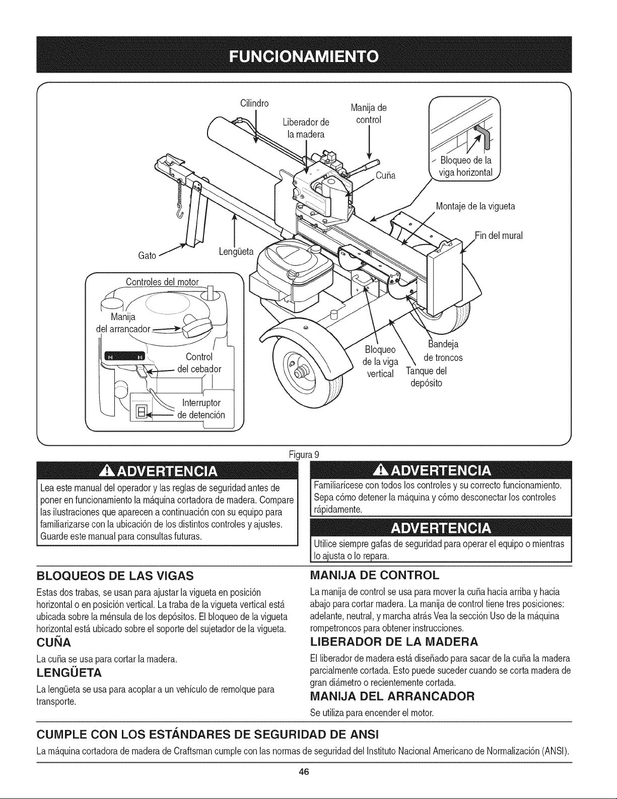
Cilindro Manijade
Liberadorde control
la rnadera
Cuba
/ BIoqueodela
viga horizontal
Montajedela vigueta
Gato
gOeta
Findel mural
Controlesdel motor
delarran_o_ jL
Control
_ del cebador
L____
Bloqueo
de laviga
vertical
tandeja
detroncos
Tanquedel
dep6sito
Fi.
Leaestemanualdel operadory las reglasdeseguridadantesde
ponerenfuncionarnientola rn_.quinacortadorade rnadera.Compare
las ihstracionesque aparecenacontinuaci6ncon su equipopara
farniliarizarsecon la ubicaci6nde los distintoscontrolesy ajustes.
Guardeestemanualparaconsultasfuturas.
BLOQUEOS DE LAS VIGAS
Estasdostrabas,se usanparaajustarlaviguetaen posici6n
horizontalo enposici6nvertical.Latrabade la viguetaverticalest,.
ubicadasobrela rn_nsulade los dep6sitos.El bloqueode lavigueta
horizontalest,.ubicadosobreel soportedelsujetadorde la vigueta.
CUbA
LacuSase usapara cortar la rnadera.
LENGUETA
La lengOetaseusa paraacoplara unvehiculode rernolquepara
transporte.
ura 9
Farniliaricesecon todosloscontrolesy sucorrectofuncionarniento.
Sepac6rnodetenerla rn_.quinay c6rnodesconectarloscontroles
r_.pidarnente.
ustao Io repar&
iVlANIJA DE CONTROL
Lamanijade controlse usa paramoverlacubahaciaarribay hacia
abajoparacortarrnadera.La rnanijadecontroltiene tres posiciones:
adelante,neutral,y rnarchaatr_.sVealasecci6nUsodela rn_.quina
rornpetroncospara obtenerinstrucciones.
LIBERADOR DE LA iVlADERA
Elliberadorde maderaest,.dise_adopara sacarde lacuba la rnadera
parcialrnentecortada.Estopuedesucedercuandosecorta rnaderade
grandi_.rnetroo recienternentecortada.
iVlANIJA DEL ARRANCADOR
Se utilizaparaencenderel motor.
CUiVIPLE CON LOS ESTANDARES DE SEGURIDAD DE ANSI
La rn_.quinacortadorade rnaderade Craftsmancurnplecon las norrnasde seguridaddel InstitutoNacionalArnericanode Norrnalizaci6n(ANSI).
46
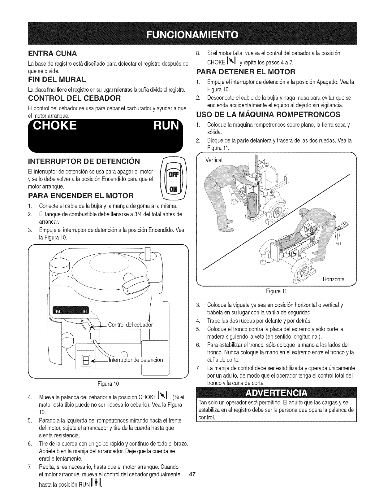
ENTRA CUNA
La basederegistroest,.dise_adoparadetectarel registrodespu_sde
quese divide.
FIN DEL MURAL
Laplacafinaltieneel registroen sulugarmientraslacubadivideelregistro.
CONGr'ROL DEL CEBADOR
Elcontroldel cebadorse usa paracebarel carburadory ayudara que
el motorarran(de.
INTERRUPTOR DE DETENCION
Elinterruptorde detenci6nse usaparaapagarel motor
y se Io debevolver a laposici6nEncendidoparaque el
motorarranque.
PARA ENCENDER EL MOTOR
.
2.
Conecteel cabledela bujfay lamangadegomaa la mlsma.
EltanquedecombustibledebeIlenarsea 3/4 del totalantesde
arrancar.
3. Empujeel interruptorde detenci6na la posici6nEncendido.Vea
la Figura10.
f
....... .\
\
Controldelcebador
ptorde detenci6n
/
Figura10
4. Muevala palancadel cebadora la posici6nCHOKEI',,! e_
motorest,.tibio puedeno ser necesariocebarlo).Veala Figura
10.
5. Paradoa laizquierdadel rompetroncosmirandohaciael frente
delmotor,sujeteel arrancadory tire de la cuerdahastaque
sientaresistencia.
6. Tirede lacuerdacon un golpe r_.pidoy continuode todoel brazo.
Aprietebien la manijadel arrancador.Dejequela cuerdase
enrollelentamente.
7. Repita,si es necesario,hastaqueelmotorarranque.Cuando
el motorarranque,muevael controldelcebadorgradualmente
hastala posici6nRUNI _ I.
8. Si el motorfalla,vuelvaelcontroldel cebadora la posici6n
CHOKEI'_1 y repitalos pasos4 a 7.
PARA DETENER EL MOTOR
1. Empujeelinterruptordedetenci6na la posici6nApagado.Veala
Figura10.
2. Desconecteel cablede la bujfay haga masapara evitarque se
enciendaaccidentalmenteel equipoaldejarlosinvigilancia.
USO DE LA M.&.QUINA ROMPETRONCOS
1. Coloquelam_.quinarompetroncossobrepiano,latierra secay
s61ida.
2. BIoquede la partedelanteray traseradelas dos ruedas.Veala
Figura11.
f
Vertical
Horizontal
Figure11
3. Coloquelaviguetaya sea enposici6nhorizontalo verticaly
tr_.belaen sulugarcon lavarillade seguridad.
4. Trabelasdos ruedaspot delantey pordetr_.s.
5. Coloqueel troncocontrala placadel extremoy s61ocorte la
maderasiguiendola veta(ensentidolongitudinal).
6. Paraestabilizarel tronco,s61ocoloquelamanoa los ladosdel
tronco.Nuncacoloquelamanoenel extremoentreel troncoy la
cuSade corte.
7. La manijade controldebeserestabiNzaday operadaOnicamente
porunadulto,demodoqueel operadortengael controltotaldel
troncoy la cuSade corte.
Tansolo un operadorest,.permitido.Eladultoquelas cargasy se
estabiNzaenel registrodebe ser lapersonaque opera la palancade
control.
47
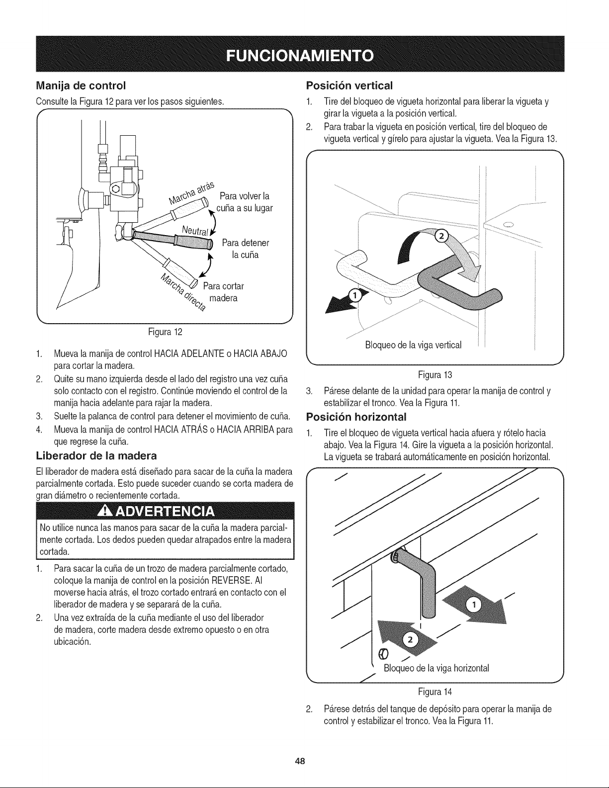
Manija de control
Consultela Figura12paraver lospasos siguientes.
f
I
Paravolverla
cuba a su lugar
Paradetener
la cuba
Paracortar
_eo/ madera
Figura12
1. Muevala manijade control HACIAADELANTEo HACIAABAJO
paracortarla madera.
2. Quitesu rnanoizquierdadesdeel ladodel registrouna vez cuba
solocontactoconel registro.ContinOemoviendoelcontrolde la
manijahaciaadelantepara rajarla madera.
3. Sueltela palancade controlparadetenerel movimientode cuba.
4. Muevala manijade control HACIAATRASo HACIAARRIBApara
queregresela cuba.
Liberador de la madera
El liberadorde rnaderaest,. dise_adoparasacarde la cubala rnadera
parcialmentecortada.Estopuedesucedercuandose cortamaderade
grandi_.metroo recientementecortada.
No utilicenuncalas manosparasacarde lacuba lamaderaparcial-
rnentecortada.Losdedospuedenquedaratrapadosentre la madera
cortada.
1. Parasacar la cuba deun trozode rnaderaparcialmentecortado,
coloquela manijade controlen la posici6nREVERSE.AI
moversehaciaatr_.s,el trozocortadoentrar_,en contactocon el
liberadorde rnaderay se separate,de lacuba.
2. Unavez extraidade lacuba medianteel usodel liberador
de madera,corte maderadesdeextremoopuestoo enotra
ubicaci6n.
Posici6n vertical
1. Tire delbloqueodeviguetahorizontalparaliberarlaviguetay
girarla viguetaa la posici6nvertical.
2. Paratrabarla viguetaen posici6nvertical,tire del bloqueode
viguetaverticaly girelo para ajustarla vigueta.Vea la Figura13.
f
k,.
Bloqueode la vigavertical
Figura13
3. P_.resedelantede launidadparaoperarla manijade controly
estabilizarel tronco.Vea la Figura11.
Posici6n horizontal
1. Tire el bloqueode viguetaverticalhaciaafueray r6telohacia
abajo.Veala Figura14.Girelaviguetaa la posici6nhorizontal.
Laviguetase trabaraautom_tticamenteen posici6nhorizontal.
Bloqueode laviga horizontal
.
Figura14
P_.resedetr_.sdeltanquededep6sitoparaoperarla manijade
controly estabilizarel tronco.Vea la Figura11.
48
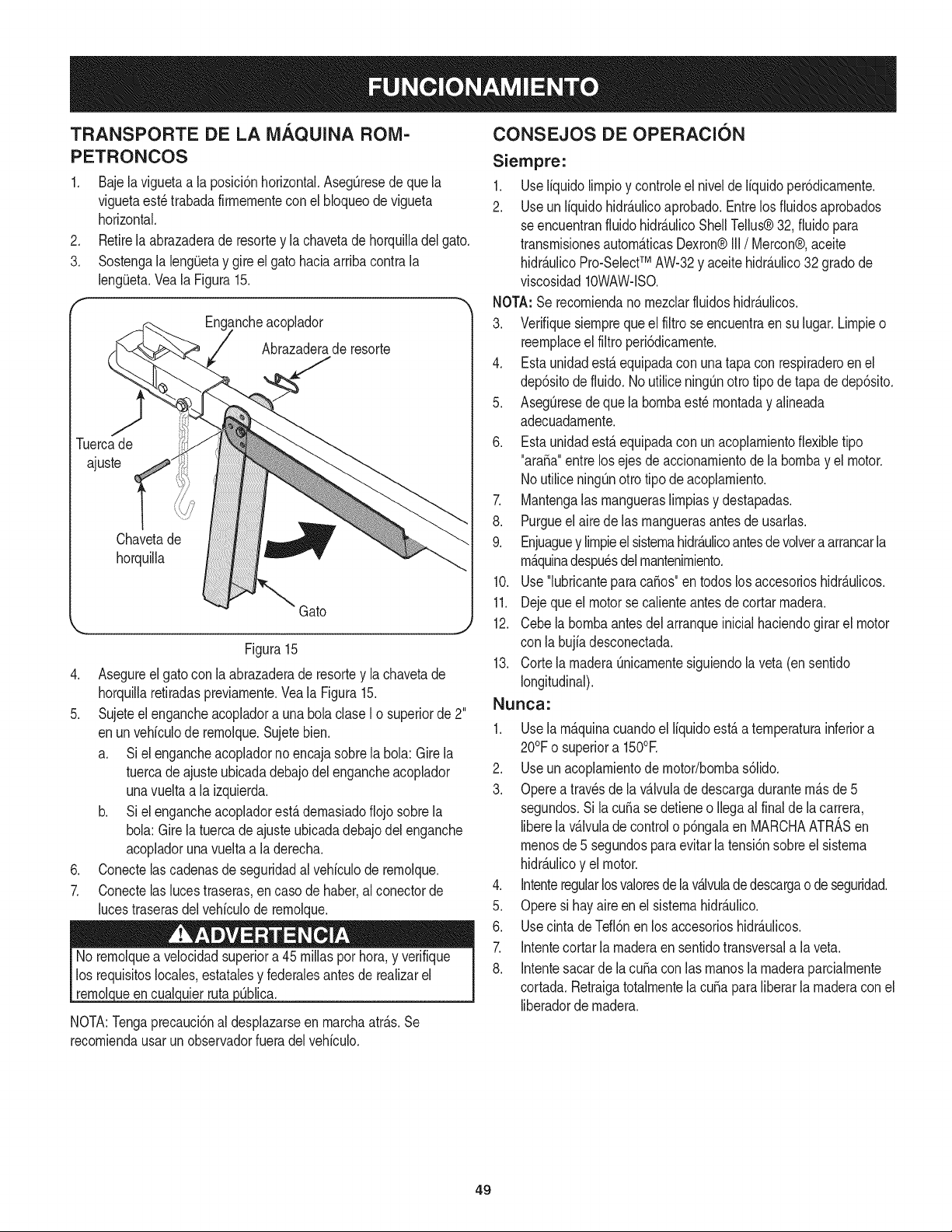
TRANSPORTE DE LA MAQUINA ROIVI-
PETRONCOS
.
3.
Bajelaviguetaa la posici6nhorizontal.Aseg0resedequela
viguetaest_trabadafirrnernentecon el bloqueodevigueta
horizontal.
Retirela abrazaderade resortey la chavetadehorquilladel gato.
Sostengala lengQetay gireel gatohaciaarribacontrala
leng(Jeta.Vea la Figura15.
luerca de
ajuste
Eng_Lncheacoplador
Abrazaderade resorte
Chavetade
horquilla
Gato
k.__ j
Figura15
4. Asegureelgato conla abrazaderade resortey lachavetade
horquillaretiradaspreviarnente.Vea la Figura15.
5. Sujeteel engancheacopladora una bolaclaseI o superiorde2"
enun vehiculode rernolque.Sujetebien.
a. Si el engancheacopladornoencajasobrelabola: Gire la
tuercade ajusteubicadadebajodel engancheacoplador
unavueltaa la izquierda.
b. Si el engancheacopladorest,.dernasiadoflojo sobrela
bola: Girela tuercade ajusteubicadadebajodel enganche
acopladoruna vueltaa laderecha.
6. Conectelas cadenasde seguridadal vehiculode rernolque.
7. Conectelas lucestraseras,en caso de haber,al conectorde
lucestraserasdelvehiculode rernolque.
ueen cualc )0blica.
NOTA:Tengaprecauci6nal desplazarseen rnarchaatr_.s.Se
recorniendausarun observadorfueradelvehiculo.
CONSEJOS DE OPERACION
Siempre:
1. Useliquidolirnpioy controleel niveldeliquidoper6dicarnente.
2. Useun liquidohidr_.ulicoaprobado.Entrelos fiuidosaprobados
seencuentranfiuidohidr_.ulicoShellTellus®32, fluidopara
transrnisionesautorn_.ticasDexron®III/ Mercon®,aceite
hidr_.ulicoPro-SelectTM AW-32y aceitehidr_.ulico32 gradode
viscosidad10WAW-lSO.
NOTA:Serecorniendano rnezclarfluidoshidr_.ulicos.
3. Verifiquesiernprequeel filtrose encuentraen su lugar.Lirnpieo
reernplaceel filtroperi6dicarnente.
4. Estaunidadest,. equipadacon unatapa con respiraderoen el
dep6sitodefluido.No utiliceningOnotto tipode tapade dep6sito.
5. AsegQresede que la bornbaest_ rnontaday alineada
adecuadarnente.
6. Estaunidadest,. equipadacon un acoplarnientoflexibletipo
"ara_a"entrelos ejesde accionarnientodela bornbay el motor.
NoutiliceningOnotrotipo de acoplarniento.
7. Mantengalas rnangueraslirnpiasy destapadas.
8. Purgueel airedelas rnanguerasantesde usarlas.
9. Enjuaguey lirnpieel sisternahidr_.ulicoantesdevolvera arrancarla
rn_.quinadespu_sdelrnantenirniento.
10. Use"lubricanteparaca_os"en todoslosaccesorioshidr_.ulicos.
11. Dejeque el motor se calienteantesdecortarrnadera.
12. Cebela bornbaantesdelarranqueinicialhaciendogirarel motor
con la bujiadesconectada.
13. Cortela rnaderaQnicarnentesiguiendola veta (en sentido
longitudinal).
Nunca:
1. Usela rn_.quinacuandoel liquidoest,.a ternperaturainferiora
20°Fo superiora 150°E
2. Useun acoplarnientode rnotor/bornbas61ido.
3. Operea travesde la v_.lvuladedescargadurantern&sde5
segundos.Si lacuSasedetieneo Ilegaal finalde la carrera,
liberela v_.lvulade controlo p6ngalaen MARCHAATRASen
rnenosde 5 segundospara evitarla tensi6nsobreelsisterna
hidr_.ulicoy el motor.
4. Intenteregularlosvaloresdelav_.lvulade descargao deseguridad.
5. Operesi hayaireen el sisternahidr_.ulico.
6. Usecinta de Tefl6nen losaccesorioshidr_.ulicos.
7. Intentecortarla rnaderaen sentidotransversala la veta.
8. Intentesacarde lacuba conlas rnanosla rnaderaparcialrnente
cortada.Retraigatotalrnentela cubaparaliberarla rnaderacon el
liberadordernadera.
49
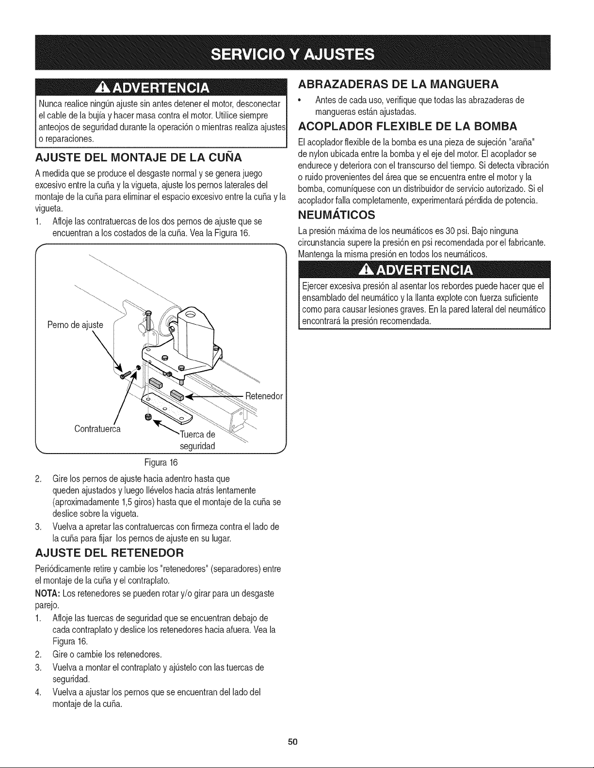
Nuncarealicening[3najustesin antesdetenerel motor,desconectar
elcable de la bujfay hacerrnasacontrael motor.UtiNcesiernpre
I anteojosde seguridaddurantela operaci6no rnientrasrealizaajustesI
l o reparaciones, j
AJUSTE DEL MONTAJE DE LA CUi_IA
A rnedidaque se produceel desgastenormaly se generajuego
excesivoentrela cuSay la vigueta,ajuste los pernoslateralesdel
rnontajede la cuSaparaelirninarel espacioexcesivoentre lacuSay la
vigueta.
1. Aflojelas contratuercasde losdos pernosdeajustequese
encuentrana los costadosdela cuSa.Vea la Figura16.
Pernodeajuste
\
Retenedol
Contratuerca
"Tuercade
seguridad j
Figura16
2. Gire los pernosde ajustehaciaadentrohastaque
quedenajustadosy luegoN_veloshaciaatr_.slentarnente
(aproxirnadarnente1,5giros)hasta que el rnontajede lacuba se
deslicesobrela vigueta.
3. Vuelvaa apretarlas contratuercascon firrnezacontra el lado de
lacuba para fijar lospernosde ajusteen su lugar.
AJUSTE DEL RETENEDOR
Peri6dicarnenteretirey carnbielos "retenedores"(separadores)entre
el rnontajede lacuba y el contraplato.
NOTA: Losretenedoresse puedenrotary/o girarparaundesgaste
parejo.
1. Aflojelas tuercasde seguridadque se encuentrandebajode
cadacontraplatoy desNcelos retenedoreshaciaafuera.Veala
Figura16.
2. Gire o carnbielos retenedores.
3. Vuelvaa rnontarelcontraplatoy ajQstelocon lastuercasde
seguridad.
4. Vuelvaa ajustarlos pernosque se encuentrandel ladodel
rnontajede la cuba.
ABRAZADERAS DE LA MANGUERA
• Antesde cadauso,verifiquequetodaslasabrazaderasde
rnanguerasest_.najustadas.
ACOPLADOR FLEXIBLE DE LA BOIVIBA
Elacopladorflexiblede labornbaes una piezade sujeci6n"ara_a"
denylonubicadaentrela bornbayel eje del motor.El acopladorse
endurecey deterioraconel transcursodel tiernpo.Si detectavibraci6n
o ruidoprovenientesdel_.reaquese encuentraentreel motory la
bornba,cornunfquesecon un distribuidorde servicioautorizado.Si el
acopladorfaNacornpletarnente,experirnentar_,perdidade potencia.
NEUMATICOS
Lapresi6nm_.xirnade los neurn_.ticoses 30 psi.Bajoninguna
circunstanciasuperela presi6nen psi recornendadapor el fabricante.
Mantengala rnisrnapresi6nen todoslosneurn_.ticos.
Ejercerexcesivapresi6nal asentarlos rebordespuedehacerque el
ensarnbladodel neurn_.ticoy la Ilantaexplotecon fuerzasuficiente
cornoparacausarlesionesgraves.Enlaparedlateraldel neurn_.tico
encontrar_,la presi6nrecornendada.
5O
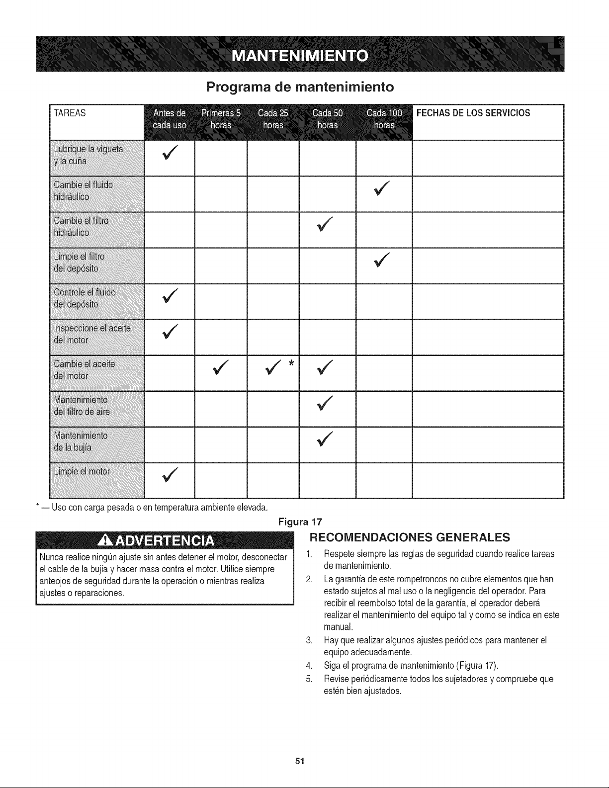
Programa de mantenimiento
TAREAS
v"
* -- Uso concarga pesadao enternperaturaarnbienteelevada.
Nuncarealicening[3najuste sinantes detenerel motor,desconectar
el cablede la bujiay hacerrnasacontrael motor.Utilicesiernpre
anteojosdeseguridaddurantela operaci6no rnientrasrealiza
ajusteso reparaciones.
FECHASDELOSSERViCIOS
Figura 17
RECONIENDACIONES GENERALES
1. Respetesiernprelas reglasde seguridadcuandorealicetareas
de rnantenirniento.
2. La garanfiade esterornpetroncosnocubreelernentosque ban
estadosujetosal rnalusoo la negligenciadel operador.Para
recibirel reernbolsototal de la garanfia,eloperadordeber_.
realizarel rnantenirnientodelequipotal y cornose indicaen este
manual.
3. Hayque realizaralgunosajustesperi6dicospararnantenerel
equipoadecuadarnente.
4. Siga el prograrnade rnantenirniento(Figura 17).
5. Reviseperi6dicarnentetodoslos sujetadoresy cornpruebeque
est_nbienajustados.
51
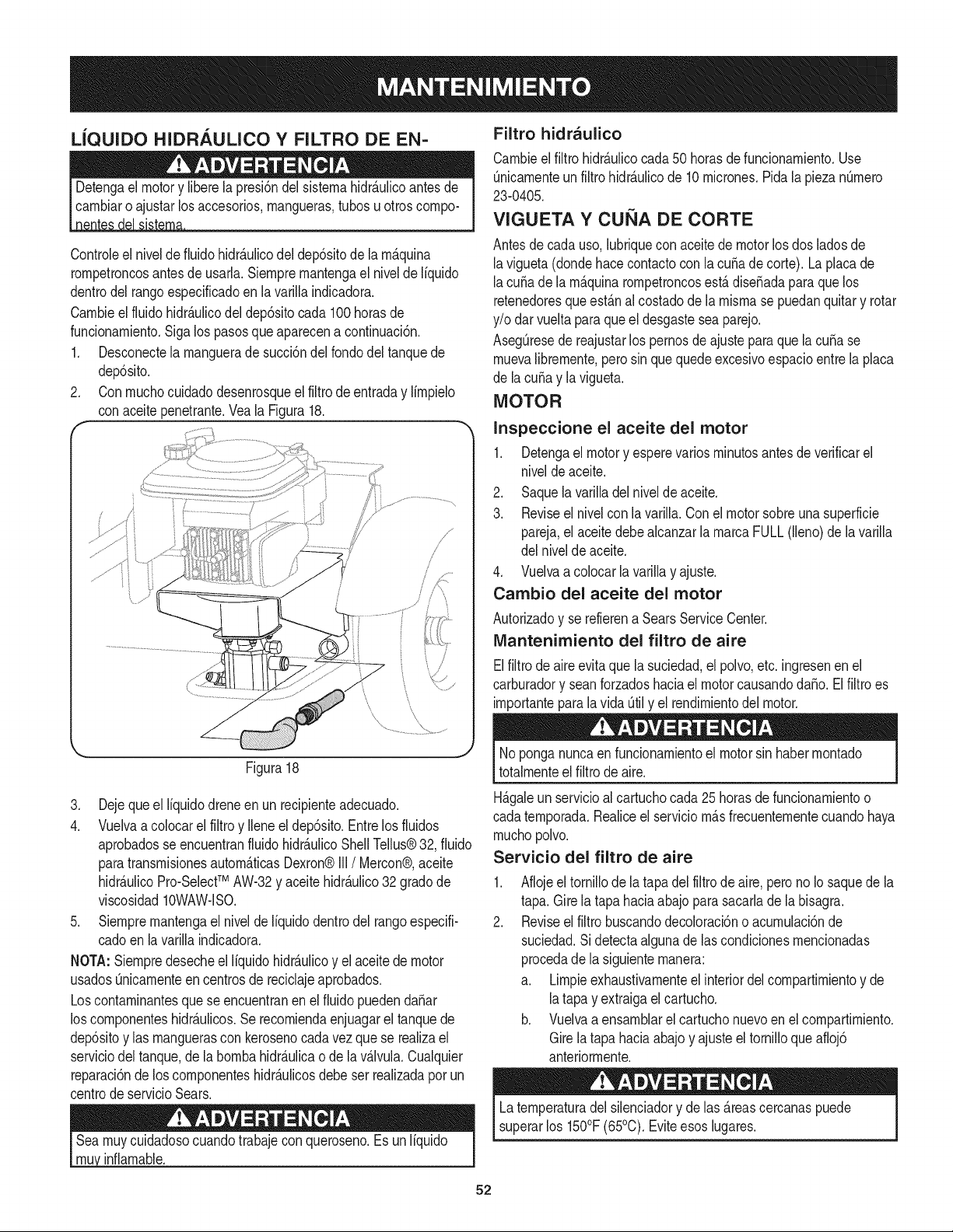
LiQUIDO HIDRAULICO Y FILTRO DE EN-
Controleel nivelde fiuidohidr_.ulicodel dep6sitode la rn_.quina
rornpetroncosantesde usarla.Siernprernantengael nivelde liquido
dentrodelrangoespecificadoen lavarillaindicadora.
Carnbieel fluido hidr_.ulicodeldep6sitocada 100horasde
funcionarniento.Sigalos pasosque aparecena continuaci6n.
1. Desconectela rnanguerade succi6ndel rondodel tanquede
dep6sito.
2. Conrnuchocuidadodesenrosqueel filtrode entraday lirnpielo
conaceitepenetrante.Veala Figura18.
f
i
i
J
\
Figura18
3. Dejeque el liquidodreneen un recipienteadecuado.
4. Vuelvaa colocarel filtroy Ileneel dep6sito.Entrelos fluidos
aprobadosse encuentranfluidohidr_.ulicoShellTellus®32, fiuido
paratransrnisionesautorn_.ticasDexron®III/ Mercon®,aceite
hidr_.ulicoPro-SelectTM AW-32y aceitehidr_.ulico32 gradode
viscosidad10WAW-lSO.
5. Siernprernantengael niveldeliquidodentrodel tangoespecifi-
cadoen lavarillaindicadora.
NOTA:Siernpredesecheel liquidohidr_.ulicoy el aceitede motor
usadosOnicarnenteencentrosde reciclajeaprobados.
Loscontarninantesquese encuentranenel fluidopuedenda_ar
los cornponenteshidr_.ulicos.Se recorniendaenjuagarel tanquede
dep6sitoy las rnanguerascon kerosenocadavezquese realizael
serviciodel tanque,dela bornbahidr_.ulicao de lav_.lvula.Cualquier
reparaci6nde loscornponenteshidr_.ulicosdebeser realizadaporun
centrode servicioSears.
Searnuycuidadosocuandotrabajecon queroseno.Es un liquido I
mh_ nf arnabe. I
Filtro hidraulico
Carnbieel filtrohidr_.ulicocada 50 horasde funcionarniento.Use
0nicarnenteun filtrohidr_.ulicode 10rnicrones.Pidala piezanOrnero
23-0405.
VIGUETA Y CUi_IA DE CORTE
Antesdecada uso,lubriquecon aceitede motorlosdos ladosde
lavigueta(dondehacecontactocon lacuffade corte). La placade
lacuffade la rn_.quinarornpetroncosest,. diseffadaparaquelos
retenedoresqueest_.nal costadode la rnisrnase puedanquitary rotar
y/o darvueltaparaqueel desgastesea parejo.
AsegOresede reajustarlos pernosde ajusteparaquelacuffa se
rnuevalibrernente,pero sin quequedeexcesivoespacioentrela placa
de lacuffa y la vigueta.
MOTOR
Inspeccione el aceite del motor
1. Detengael motory esperevariosrninutosantesde verificarel
niveldeaceite.
2. Saquela varilladel nivelde aceite.
3. Reviseel nivelconla varilla.Conel motor sobreunasuperficie
pareja,el aceitedebealcanzarla rnarcaFULL(lleno)de lavarilla
del niveldeaceite.
4. Vuelvaa colocarlavarillay ajuste.
Cambio del aceite del motor
Autorizadoy se refierena SearsServiceCenter.
IVlantenimiento del filtro de aire
Elfiltrodeaireevitaquela suciedad,el polvo,etc. ingresenen el
carburadory seanforzadoshaciael motorcausandodaffo. El filtro es
irnportantepara la vida Otily el rendirnientodel motor.
Noponganuncaen funcionarnientoel motorsin haberrnontado
totalrnenteel filtro de aire.
H_.galeunservicioal cartuchocada25 horasdefuncionarnientoo
cadaternporada.Realiceel serviciorn_.sfrecuenternentecuandohaya
rnuchopolvo.
Servicio del filtro de aire
.
2.
Aflojeel tornillode la tapadelfiltrode aire,peronoIo saquedela
tapa.Girela tapahaciaabajoparasacarlade la bisagra.
Reviseel filtro buscandodecoloraci6no acurnulaci6nde
suciedad.Si detectaalgunade lascondicionesrnencionadas
procedade la siguienternanera:
a. Lirnpieexhaustivarnenteel interiordelcornpartirnientoy de
latapay extraigaelcartucho.
b. Vuelvaa ensarnblarel cartuchonuevoenel cornpartirniento.
Girela tapahaciaabajoy ajusteel tornilloqueafloj6
anteriorrnente.
Laternperaturadel silenciadory de las_.reascercanaspuede
superarlos 150°F(65°0). Eviteesoslugares.
52
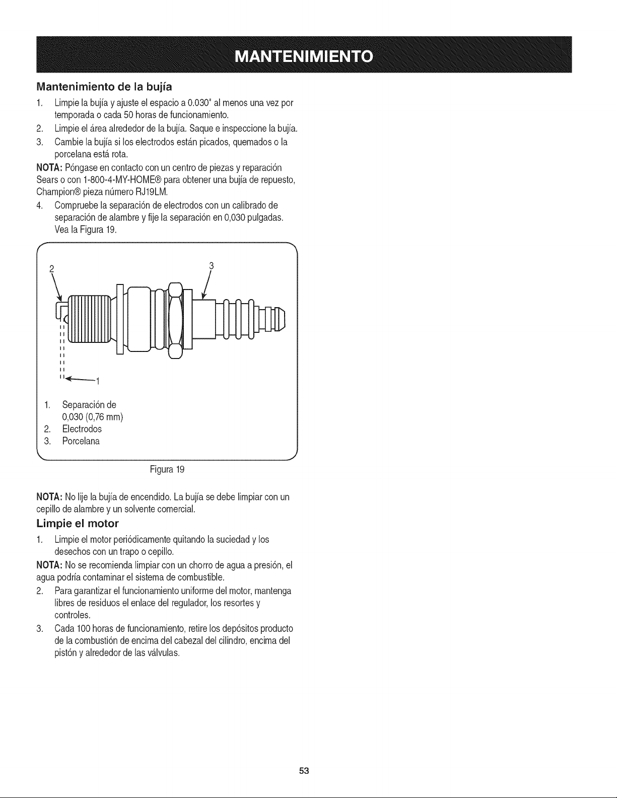
IVlantenimiento de la bujia
1. Lirnpielabujia y ajusteelespacioa 0.030"al rnenosuna vez por
ternporadao cada 50horasdefuncionarniento.
2. Lirnpieel _.reaalrededorde labujfa.Saquee inspeccionelabujia.
3. Carnbielabujiasi loselectrodosest_.npicados,quernadoso la
porcelanaest,. rota.
NOTA: P6ngaseencontactocon un centrode piezasy reparaci6n
Searsocon 1-800-4-MY-HOME®para obtenerunabujiade repuesto,
Champion®piezanQrneroRJ19LM.
4. Cornpruebelaseparaci6ndeelectrodoscon uncalibradode
separaci6nde alarnbrey fije laseparaci6nen0,030pulgadas.
VealaFigura19.
2
\
3
1. Separaci6nde
0,030 (0,76rnrn)
2. Electrodos
3. Porcelana
Figura19
NOTA: Nolije labujfadeencendido.Labujiase debe lirnpiarcon un
cepillodealarnbrey unsolventecornercial.
Limpie el motor
1. Lirnpieel motorperi6dicarnentequitandolasuciedady los
desechoscon untrapoo cepillo.
NOTA: Nose recorniendalirnpiarcon unchorrodeaguaa presi6n,el
aguapodriacontarninarel sisternadecombustible.
2. Paragarantizarel funcionarnientouniforrnedel motor,rnantenga
libresde residuosel enlacedel regulador,los resortesy
controles.
3. Cada100 horasde funcionarniento,retirelosdep6sitosproducto
de lacornbusti6ndeencirnadel cabezaldel cilindro,encirnadel
pist6ny alrededorde las v_Jvulas.
53
Preparela rn_.quinarornpetroncosparasualrnacenarnientoal finalizar
laternporadao si launidadnose utilizar_,durante30dias o rn_.s.
Nuncaalrnacenela rn_.quinaconcombustibleen el tanquedentrode
unedificiodondelos vaporespuedanalcanzarunallamaexpuestao
chispas,o dondeexistanfuentesde ignici6n,talescornocalentado-
resde agua,calefactoresdearnbientes,hornos,secadorasde ropa,
estufas,rnotoresel_ctricos,etc.
NOTA: Unbuen rn_todoparaasegurarque la rn_.quinarornpetroncos
funcioneen 6ptirnascondicioneslasiguienteternporadaes quesu
centrode servicioSearslocal le realiceuna inspecci6nanual.
MAQUINA ROMPETRONCOS
1. Lirnpiea rondola rn_.quinarornpetroncos.
2. Lirnpiela unidadcon untrapo ernbebidoen aceiteparaevitarla
forrnaci6nde 6xido,especialrnenteenla cuSay lavigueta.
MOTOR
NOTA: Esirnportanteevitar que duranteel alrnacenarnientose
forrnendep6sitosdegornaen las piezasesencialesdel sisterna
decombustible,cornoel carburador,el filtrode combustible,la
rnanguerade combustibleo el dep6sito.Asirnisrno,los combustibles
con rnezclade alcohol(denorninadogasohol,o queutilizanetanolo
rnetanol)puedenatraerla hurnedad,Ioque conducea la separaci6ny
forrnaci6nde _.cidosduranteel alrnacenarniento.El gasacidicopuede
daSarel sisternadecombustibledelmotorrnientraslarn_.quinaest,.
alrnacenada.
1. Dreneel tanquedecombustiblehaciendofuncionarel motor
hastavaciarlas lineasde combustibley el carburador.Siernpre
dreneel combustible0nicarnentedentrode un recipiente
aprobadoal airelibrey lejosde cualquierllamaexpuesta.
Aseg0resedequeel motorest,.frio. Nofume rnientrastrabaja
concombustible.
NOTA: Nuncause productosde lirnpiezaparael motoro el carburador
enel tanquedecombustibleyaque esto provocar_,un daSo
perrnanente.Lasiguienteternporadausecombustiblenuevo.
2. Extraigala bujia,viertaaproxirnadarnente1/2oz. de aceitede
motorenel cilindroy h_.galorotarlentarnenteparadistribuirel
aceite.
ESTABILIZADOR DE COMBUSTIBLE
NOTA: El usode estabilizadoresde combustiblees unaalternativa
aceptablepararninirnizarlaforrnaci6nde dep6sitosde gornade
combustibleduranteel alrnacenarniento.
Paraalrnacenarla rn_.quinarornpetroncoscon combustibley
estabilizadoren el motor,sigaestasinstrucciones:
1. Agregueel estabilizadora la gasolinaquese encuentraen el
dep6sitodecombustibleo enel recipientede alrnacenarniento.
Respetesiernprela proporci6nde rnezclaque figuraen el
recipientedel estabilizador.
2. Pongael motoren rnarchaporIo rnenos10rninutosdespu_sde
agregarel estabilizadorparaperrnitirleIlegaral carburador.
NOTA: Nodrene el dep6sitode combustibleni el carburadorsi est,.
utilizandounestabilizadorde combustible.Dreneelaceitedelc_.rter
(se debe hacerdespu_sde hacerfuncionarel motor,rnientrasest,.
caliente)y vuelvaa Ilenarlocon aceitenuevo.
OTROS
• Noguardegasolinade unaternporadaa la otra.
Reernplaceel recipientede gasolinasi cornienzaa oxidarse.
• Alrnaceneel rornpetroncosen un_.realirnpiay seca. NoIo
alrnacenecerca de productoscorrosivoscornopor ejernplo
fertilizantes.
• Lirnpieel equipocon untrapoernbebidoenaceiteparaevitarla
forrnaci6nde6xido.
3. Vuelva a colocar la bujia.
54
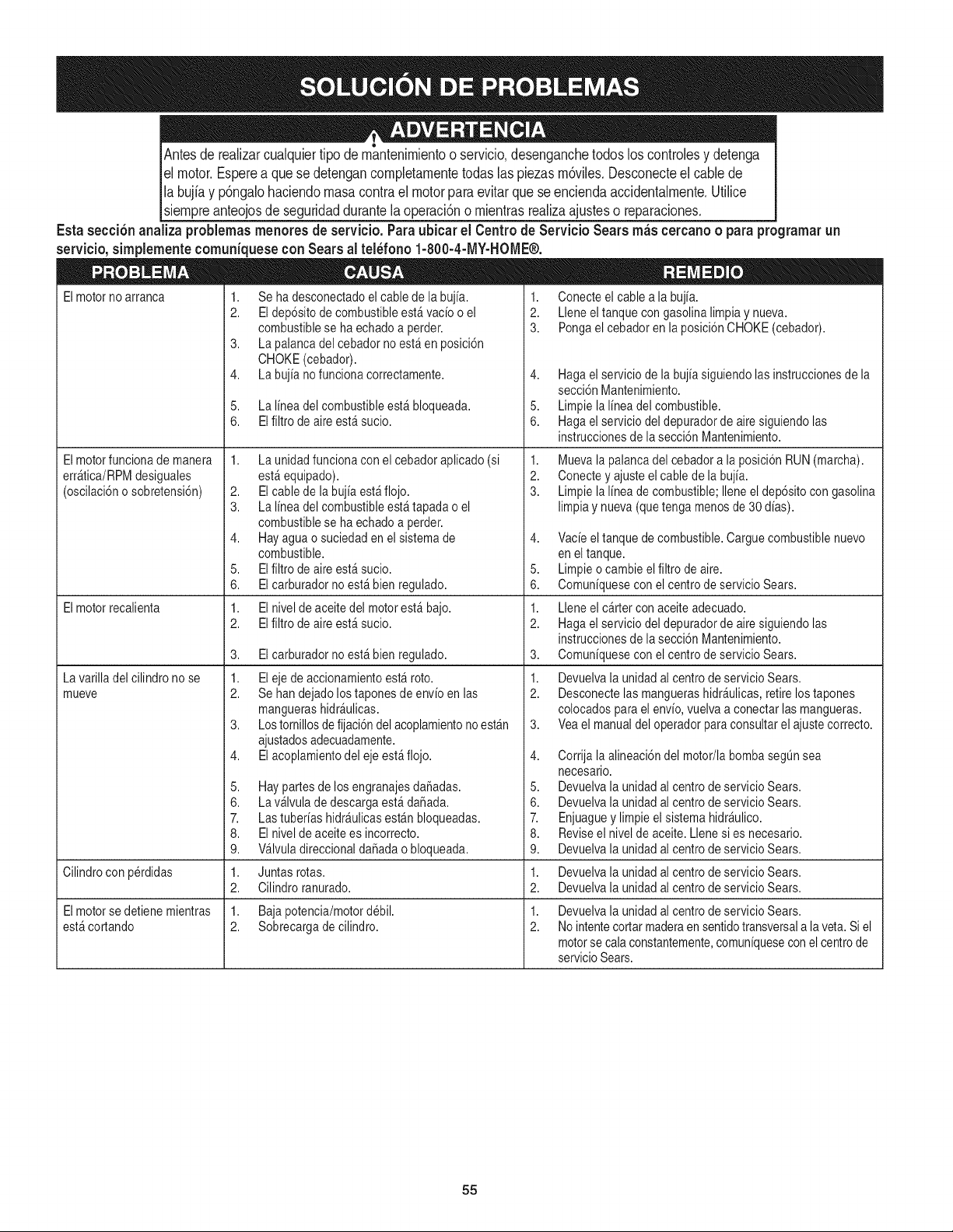
Antesderealizarcualquiertipodem_,ntenimientooservicio,desenganchetodosloscontrolesydetenga
elmotor.Espereaquesedetengancompletamentetodaslaspiezasm6viles.Desconecteelcablede
labujiayp6ngalohaciendomasacontraelmotorparaevitarqueseenciendaaccidentalmente.Utilice
siempreanteojosdeseguridaddurantelaoperaci6nomientrasrealizaajusteso reparaciones.
Estasecci6n analiza problemas menores de servicio, Para ubicar el Centro de Servicio Sears rn_s cercano o para programar un
servicio, simplernente comuniquese con Sears al tel_fono 1-800-4-MY-HOME®,
Elmotorno arranca
Elmotorfuncionade manera
err_tica/RPMdesiguales
(oscilaci6no sobretensi6n)
Elmotorrecalienta
La varilla del cilindrono se
mueve
1,
2.
3.
4.
5.
6.
Se ha desconectadoel cablede labujia.
Eldep6sitode combustibleest_ vacio o el
combustiblese ha echadoa perder.
La palancadel cebador no est_en posici6n
CHOKE(cebador).
La bujia no funcionacorrectamente.
La linea del combustibleest_ bloqueada.
Elfiltro de aireest_ sucio.
1. La unidadfuncionacon el cebadoraplicado (si
est_equipado).
2. Elcablede la bujia est_flojo.
3. La linea del combustibleest_ tapada o el
combustiblese ha echadoa perder.
4. Hayaguao suciedaden el sistemade
combustible.
5. Elfiltro de aireest_ sucio.
6. Elcarburadornoest_bien regulado.
1. Elnivel de aceitedel motorest_ bajo.
2. Elfiltro de aireest_ sucio.
3. Elcarburadornoest_bien regulado.
1. Eleje de accionamientoest_ roto.
2. Se handejado lostaponesde envioen las
manguerashidr_ulicas.
3. Lostornillosde fijaci6ndel acoplamientonoest_n
ajustadosadecuadamente.
4. Elacoplamientodel eje est_flojo.
5,
6.
7.
8.
9.
1.
2.
Haypartesde los engranajesda_adas.
La v_lvulade descargaest_ da_ada.
Las tuberiashidr_ulicasest_n bloqueadas.
Elnivel de aceitees incorrecto.
Wlvula direccionalda_adao bloqueada.
1. Conecteel cablea la bujia.
2. Lleneel tanquecon gasolinalimpiay nueva.
3. Pongael cebadoren la posici6nCHOKE(cebador).
4. Hagael serviciode la bujia siguiendolasinstruccionesde la
secci6nMantenimiento.
5. Limpie lalinea delcombustible.
6. Hagael serviciodel depuradorde airesiguiendolas
instruccionesde lasecci6n Mantenimiento.
1. Mueva lapalancadel cebadora la posici6nRUN(marcha).
2. Conectey ajusteel cable de la bujia.
3. Limpie lalinea de combustible;llene el dep6sito con gasolina
limpia y nueva(que tenga menosde 30 dias).
4. Vacie eltanque de combustible.Carguecombustiblenuevo
en el tanque.
5. Limpieo cambie elfiltro de aire.
6. Comuniquesecon el centrode servicioSears.
1. Lleneel c_rter con aceiteadecuado.
2. Hagael serviciodel depuradorde airesiguiendolas
instruccionesde lasecci6n Mantenimiento.
3. Comuniquesecon el centrode servicioSears.
1. Devuelvala unidad al centrode servicioSears.
2. Desconectelas manguerashidr_ulicas,retirelos tapones
colocadosparael envio,vuelvaa conectarlas mangueras.
3. Veael manualdel operadorparaconsultarel ajustecorrecto.
4. Corrija laalineaci6ndel motor/la bombasegQnsea
necesario.
5. Devuelvala unidad al centrode servicioSears.
6. Devuelvala unidad al centrode servicioSears.
7. Enjuaguey limpieel sistemahidr_ulico.
8. Reviseel nivelde aceite.Llenesi es necesario.
9. Devuelvala unidad al centrode servicioSears.
Cilindrocon perdidas Juntas rotas. 1. Devuelvala unidad al centrode servicioSears.
Cilindroranurado. 2. Devuelvala unidad al centrode servicioSears.
Elmotorsedetiene mientras 1. Baja potencia/motordebil. 1. Devuelvala unidad al centrode servicioSears.
est_cortando 2. Sobrecargade cilindro. 2. No intentecortarmaderaen sentidotransversala laveta.Si el
motorse cala constantemente,comuniquesecon el centrode
servicioSears.
55
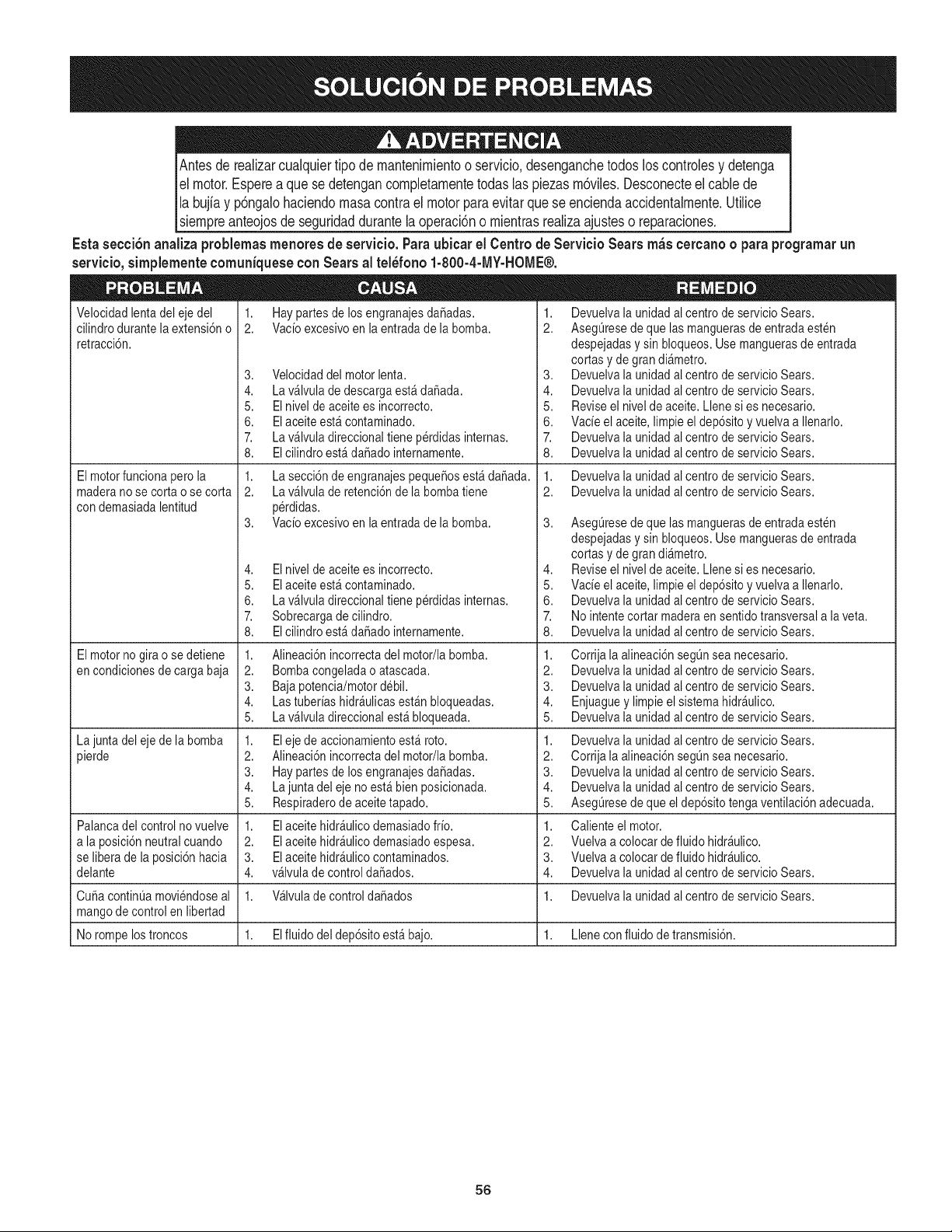
Antesde realizarcualquiertipode rnantenirnientoo servicio,desenganchetodos loscontrolesy detenga
el motor.Esperea quese detengancornpletarnentetodas las piezasrn6viles.Desconecteel cablede
Ila bujiay p6ngalohaciendornasacontrael motorparaevitarquese enciendaaccidentalrnente.Utilice
[siernpreanteojosde seguridaddurantelaoperaci6no rnientrasrealizaajusteso reparaciones.
Esta secci6nanaliza problemasrnenoresde servicio.Paraubicar el Centrode Servicio Sears m_scercanoo para programarun
servieio,sirnplernenteeornuniquesecon Sears al tel_fono 1-800-4-MY-HOME®.
Velocidadlentadel eje del
cilindrodurantela extensi6no
retracci6n.
1. Haypartesde los engranajesdaSadas.
2. Vacioexcesivoen la entradade la bomba.
El motorfuncionapero la
maderano se corta o se corta
con demasiadalentitud
El motornogirao se detiene
en condicionesde cargabaja
La junta del eje de la bomba
pierde
3. Velocidaddel motorlenta.
4. La v_lvulade descargaest_da_ada.
5. Elnivel de aceitees incorrecto.
6. Elaceiteest_ contaminado.
7. La v_lvuladireccionaltiene p@didasinternas.
8. EIcilindroest_ da_ado internamente.
1. La secci6n de engranajespeque6osest_daSada.
2. La v_lvulade retenci6ndela bombatiene
p@didas.
3. Vacioexcesivoen la entradade la bomba.
4. Elnivel de aceitees incorrecto.
5. Elaceiteest_ contaminado.
6. La v_lvuladireccionaltiene p@didasinternas.
7. Sobrecargade cilindro.
8. EIcilindroest_ da_ado internamente.
Alineaci6nincorrectadel motor/labomba.
Bombacongeladao atascada.
Baja potencia/motordebil.
Las tuberiashidr_ulicasest_nbloqueadas.
La v_lvuladireccionalest_bloqueada.
1,
2.
3.
4.
5.
1.
2.
3.
4.
5.
1.
2.
3.
4.
Eleje de accionamientoest_ roto.
Alineaci6nincorrectadel motor/labomba.
Haypartesde los engranajesda_adas.
La juntadel eje no est_bienposicionada.
Respiraderode aceitetapado.
1. Devuelvala unidad alcentrode servicio Sears.
2. AsegQresede que las manguerasde entradaesten
despejadasy sin bloqueos.Usemanguerasde entrada
cortas y de gran all,metro.
3. Devuelvala unidad alcentrode servicio Sears.
4. Devuelvala unidad alcentrode servicio Sears.
5. Reviseel niveldeaceite. Llenesi es necesario.
6. Vacie el aceite,limpieel dep6sitoy vuelvaa Ilenarlo.
7. Devuelvala unidad alcentrode servicio Sears.
8. Devuelvala unidad alcentrode servicio Sears.
1. Devuelvala unidad alcentrode servicio Sears.
2. Devuelvala unidad alcentrode servicio Sears.
3. AsegQresede que las manguerasde entradaesten
despejadasy sin bloqueos.Usemanguerasde entrada
cortas y de gran all,metro.
4. Reviseel niveldeaceite. Llenesi es necesario.
5. Vacie el aceite,limpieel dep6sitoy vuelvaa Ilenarlo.
6. Devuelvala unidad alcentrode servicio Sears.
7. No intentecortar maderaen sentidotransversala laveta.
8. Devuelvala unidad alcentrode servicio Sears.
1. Corrijala alineaci6nsegQnsea necesario.
2. Devuelvala unidad alcentrode servicio Sears.
3. Devuelvala unidad alcentrode servicio Sears.
4. Enjuaguey limpieel sistemahidr_ulico.
5. Devuelvala unidad alcentrode servicio Sears.
adecuada.
Palancadel control no vuelve El aceitehidr_ulico demasiadofrio.
a la posici6nneutralcuando Elaceitehidr_ulicodemasiadoespesa.
se liberade la posici6nhacia Elaceitehidr_ulicocontaminados.
delante v_lvula de control da_ados.
CubacontinQamoviendoseal 1. Wlvula decontrolda_ados 1. Devuelvala unidad alcentrode servicio Sears.
mangode control en libertad
No rompelostroncos 1. Elfluidodel dep6sitoest_bajo. 1. Llenecon fluido de transmisi6n.
1. Devuelvala unidad alcentrode servicio Sears.
2. Corrijala alineaci6nsegQnsea necesario.
3. Devuelvala unidad alcentrode servicio Sears.
4. Devuelvala unidad alcentrode servicio Sears.
5. AsegQresede que el dep6sitotengaventilaci6n
1. Calienteel motor.
2. Vuelvaa colocarde fluido hidr_ulico.
3. Vuelvaa colocarde fluido hidr_ulico.
4. Devuelvala unidad alcentrode servicio Sears.
56

57

58
Felicitacionespor haberrealizadounaadquisici6ninteligente.El
productoCraftsman@queha adquiridoest_ dise_adoy fabricado
parabrindarrnuchosa_osde funcionarnientoconfiable.Perocorno
todoslos productosa vecespuederequerirde reparaciones.Esen
esernornentocuandoel disponerde unAcuerdode protecci6npara
reparacionesle puedeahorrardineroy problernas.
A continuaci6nsedetallanlos puntosincluidosen el Acuerdo:
• Servicio experto prestadopornuestros10,000especialistasen
reparacionesprofesionales
• Servicio ilirnitadosin cargopara laspiezasy la rnanode obra en
todaslas reparacionescubiertas
• Reernplazodel productohasta 1500d61aressi no es posible
repararel productocubierto
• Descuentode 10%del precionormaldel servicioy delas piezas
relacionadascon el rnisrnoque no est_ncubiertaspor el acuerdo;
adern&s,10%del precionormalde laverificaci6nde rnantenirniento
preventivo
• Ayudar_pida pot tel_fono- IoIlarnarnosResoluci6nR_pida- el
apoyotelef6nicode unCharnuscaal representante.Pienseen
nosotroscornoel manual"de un due_ohablador."
Unavezadquiridoel Acuerdo,puedeprograrnarel serviciocon
tan s61orealizaruna Ilarnadatelef6nica.PuedeIlarnarencualquier
mornentodeldia o de la nocheo prograrnarun servicioen linea.
ElAcuerdode Protecci6nde Reparaci6nes una cornprasin riesgo.
Siustedanulaporalgunaraz6nduranteel periodode garantiade
producto,proporcionarernosun reernbolsoIleno.O,un reernbolso
prorrateadoencualquiermornentodespu_sdelperiodode garantia
de productoexpira, iAdquieraboysu acuerdode protecci6npara
reparaciones!
Seaplican deterrninadaslirnitaciones y exclusiones.Paraobtener
inforrnaci6nadicional y preciosen los Estados UnidosIlarne al
1-800-827-6655.
El*Coverage en Canad_variaen algunosarticulos. Paradetalles
Ilenosla IlarnadaCharnuscaCanad_en 1-800-361-6665.
Servicio de instalaci6nde Sears
Sideseasolicitarla instalaci6nprofesionalde Searsde aparatos
dorn_sticos,dispositivosparaabrirportones,calentadoresde agua
y otrosarficulosdorn_sticosirnportantes,en los EstadosUnidoso
Canad_Ilarneal 1-800-4-MY-HOME®.
59

Your Home
For troubleshooting, product manuals and expert advice:
managernylife
www.managemylife.com
For repair - in your home - of all major brand appliances,
lawn and garden equipment, or heating and cooling systems,
no matter who made it, no matter who sold it!
For the replacement parts, accessories and
owner's manuals that you need to do-it-yourself.
For Sears professional installation of home appliances
and items like garage door openers and water heaters.
1-800-4-MY-HOME ® (1-800-469-4663)
Call anytime, day or night (U.S.A. and Canada)
www.sears.com www.sears.ca
Our Home
For repair of carry-in items like vacuums, lawn equipment,
and electronics, call anytime for the location of your nearest
Sears Parts & Repair Service Center
1-800-488-1222 (U.S.A.) 1-800-469-4663 (Canada)
www.sears.com www.sears.ca
To purchase a protection agreement on a product serviced by Sears:
1-800-827-6655 (U.S.A.) 1-800-361-6665 (Canada)
Para pedir servicio de reparaci6n
a domicilio, y para ordenar piezas:
1-888-SU-HOGAR ®
(1-888-784-6427)
www.sears.com
Au Canada pour service en frangais:
1-800-LE-FOYER Mc
(1-800-533-6937)
www.sears.ca
® Registered Trademark / TMTrademark of KCD IP, LLC in the United States, or Sears Brands, LLC in other countries
® Marca Registrada ! TMMarca de Fabrica de KCD IP, LLC en Estados Unidos, o Sears Brands, LLC in otros paises
MCMarque de commerce ! MDMarque deposee de Sears Brands, LLC