Loading ...
Loading ...
Loading ...
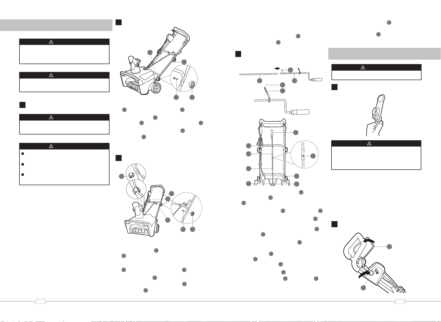
UNPACK THE MACHINE
INSTALL THE MIDDLE HANDLE
INSTALL THE CHUTE CONTROL
ROD
USE THE CORD RETAINER
START THE MACHINE
INSTALL THE UPPER HANDLE
Do not change or make accessories that
are not recommended by the manufac-
turer.
WARNING
Do not connect to power supply until
you assemble all the parts.
WARNING
Make sure that you correctly assemble
the machine before use.
WARNING
Wear eye protection during operation.
WARNING
Do not plug the extension cable into the
outlet until it has been connected to the
cord retainer and plugged into the
machine.
NOTE
If the parts are damaged, do not use
the machine.
If you do not have all the parts, do not
operate the machine.
If the parts are damaged or missing,
speak to the service center.
Open the package.
Read the documentation in the box.
Remove all the unassembled parts
from the box.
Remove the machine from the box.
Discard the box and package in
compliance with local regulations.
1.
2.
3.
4.
5.
Align the holes in the middle handle
( )and the lower handle ( ).
Put the bolts ( ) through the middle
handle ( ) and the lower handle ( ).
Tighten the handle knob ( ) onto
the bolt ( ).
Repeat for left/right side.
1.
2.
3.
4.
Put the cord retainer between the
upper handle ( ) and middle handle
( ).
Align the holes in the middle handle
( ) and the upper handle ( ).
Put the bolts ( ) through the holes.
Tighten the handle knobs ( ) onto
the bolts ( ).
1.
2.
3.
Do the same operation on the other
side.
Attach the cable clamp ( ) to the
middle handle ( ).
4.
5.
Connect the upper lever ( ) and
lower lever ( ) with 1 screw supplied
( ).
Unscrew the nut ( ) and washers( ).
Put the bolt of the upper lever ( )
through the hole in the middle
handle. And install the washers ( )
and nut ( ).
Pull out of the hitch pin ( ). And
then put the end of the chute
control rod ( ) straight through the
hole ( ) in the bracket. And Keep
the grip handle ( ) down.
Put the hitch pin ( ) through the
chute control rod ( ) and hole ( ).
1.
2.
3.
4.
5.
Turn the grip handle ( ) left and
right to make sure that the
discharge chute ( ) moves in the
same direction.
6.
Fold the extension cable to form a
tight loop near the retainer.
Push the loop through the bottom
hole in the retainer.
Move the loop over the retaining
clip, and pull until the cable is
secured.
1.
2.
3.
WARNING
INSTALLATION
OPERATION
05
https://www.altonindustries.com
06
info@altonindustries.com
4
6
21 14
3
22
4
13
21 14
15 16
18
22
17
23
5
17
19
20
16
15
18
2
12
4
4
3
3
4
4
6
6
14
14
21
21
21
21
4
22
16
17
18
18
19
19
22
22
20
20
23
10
23
5
5
15
15
Loading ...
Loading ...
Loading ...