Loading ...
Loading ...
Loading ...
Installation Instructions
[]_]INSTALL THE DRAIN{S)
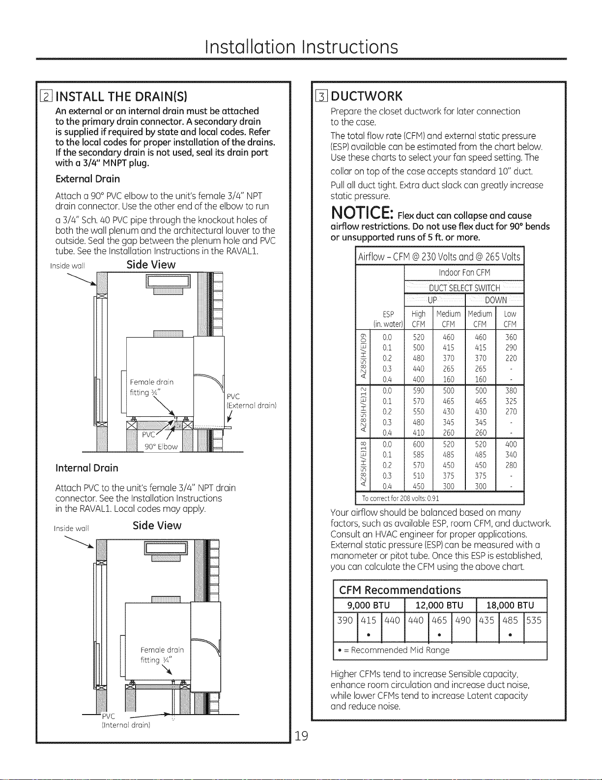
An externaloran internaldrainmustbeattached
totheprima_ drainconnector.A secondarydrain
issuppliedifrequiredbystateand localcodes.Refer
tothelocalcodesforproperinstallationofthedrains.
Ifthesecondarydrainisnotused,sealitsdrainport
witha 3/4"MNPT plug.
External Drain
Attach a 90° PVCelbow to the unit's female 3/4" NPT
drain connector. Usethe other end ofthe elbow to run
a 3/4" Sch.40 PVCpipe through the knockout holes of
both the wall plenum and the architectural louver to the
outside.Sealthe gap between the plenum hole and PVC
tube. Seethe Installation Instructions in the RAVAL1.
Inside wall Side View
ii !i!
PVC
xternal drain)
Internal Drain
Attach PVCto the unit'sfemale 3/4" NPTdrain
connector. Seethe Installation Instructions
in the RAVAL!.Localcodes may apply.
Inside wall Side View
-- PVC
(Internal drain)
19
%
DUCTWORK
Prepare the closet ductwork for later connection
to the case.
Thetotal flow rate (CFM)and external static pressure
(ESP)available can be estimated from the chart below.
Usethese charts to selectyour fan speedsetting. The
collar on top of the case accepts standard 10" duct.
Pullall duct tight. Extra duct slackcan greatly increase
static pressure.
NOTICE:Fie×duct con collapseand cause
airflow restrictions. Do not use flex duct for 90° bends
or unsupported runs of 5 ft. or more,
Airflow - CFM@230Voltsand @265 Volts
ESP
(in,water)
8 o.o
0.1
0.2
8 o.s
< 0./4
8 o.o
04
z 0.2
0.3
0.4
IndoorFanCFM
DUCTSELECTSWITCH
UP i DOWN
High
CFM
52O
500
480
440
4OO
590
570
550
480
410
Medium Medium
CFM CFM
460 460
415 415
370 370
265 265
160 160
500 500
465 465
430 430
345 345
260 260
Low
CFM
36O
29O
22O
380
325
27O
0.0 600
0.i 585
z 0.2 570
0.3 510
0.4 450
Tocorrectfor208volts:0.91
520 520 400
485 485 340
450 450 280
375 375
300 300
Your airflow should be balanced based on many
factors, such as available ESP,room CFH,and ductwork.
Consultan HVACengineer for proper applications.
External static pressure (ESP)can be measured with a
manometer or pitot tube. Oncethis ESPisestablished,
you can calculate the CFHusing the above chart.
CFM Recommendations
9,000 BTU 12,000 BTU
390 415 440 440 465 490
e e
• = Recommended Mid Range
18,000 BTU
435 485 535
e
Higher CFHstend to increase Sensiblecapacity,
enhance room circulation and increase duct noise,
while lower CFMstend to increase Latent capacity
and reduce noise.
Loading ...
Loading ...
Loading ...