Loading ...
Loading ...
Loading ...
8
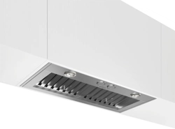
Install the range hood into the hood cabinet
1 Determine and make all necessary cuts in the wall or roof for
the vent system. Install the vent system before installing the
cabinethoodinsert.Seethe“VentingRequirements”section.
2 Determine the location where the power supply cable will be
run through the wall.
3 Drilla1¼”(3.2cm)holeatthislocation.
4 Pullenoughpowersupplycablethroughthewalltoallowfor
easy connection to the terminal box.
5 Remove terminal box cover and set aside.
6 Installthe10”(25.4cm)squarex10”(25.4cm)roundvent
transition with damper to top side of the range hood, using 4 -
3.5x9.5mmscrews.
7 Remove knockout from the top of the vent hood and install a
ULlistedorCSAapproved½”(1.3cm)strainrelief.
8 Placethehoodinsertnearitsmountingpositionandrunthe
power supply cable through the strain relief into terminal box
(enoughtomakeconnection).
9 Tighten the strain relief screws.
10 Using 2 or more people, lift the hood insert into hood cabinet.
11 Fastenthehoodinsertusingfour5x45mmscrewstothe
hood cabinet and tighten securely.
WARNING
EXCESSIVE WEIGHT HAZARD
USE TWO OR MORE PEOPLE TO MOVE AND INSTALL HOOD
INSERT.
FAILURE TO DO SO CAN RESULT IN BACK OR OTHER
INJURY.
UpperHood
InsertMotorHousing
4 mounting
screws
Electrical connection
I WARNING
ELECTRICALSHOCKHAZARD.
I WARNING
DISCONNECTPOWERBEFORESERVICING.
REPLACEALLPARTSANDPANELSBEFOREOPERATING.
FAILURETODOSOCANRESULTINDEATHOR
ELECTRICALSHOCK.
1 Disconnect power.
2 Locateterminalboxinsideofthehoodinsert.
A
B
C
D
E
G
F
A.Whitewires
B. Black wires
C.ULlistedwireconnectors
D.Green,bareoryellow/greenwires
E.Homepowersupply
F.ULlistedorCSAapproved¹⁄
2
”(1.3cm)
strain relief
G. Ground Wire tab
3 UseULlistedwireconnectorsandconnectblackwires(B)
together.
4 UseULlistedwireconnectorsandconnectwhitewires(A)
together.
I WARNING
ELECTRICALLYGROUNDBLOWER.
CONNECTGROUNDWIRETOGREENANDYELLOW
GROUNDWIREINTERMINALBOX.FAILURETODOSOCAN
RESULTINDEATHORELECTRICALSHOCK.
5 Connectgreen(orbare)groundwirefromhomepowersupply
tothegreen/yellowgroundwire(D)interminalboxusingUL
listed wire connectors.
6 Install terminal box cover.
7 Check that all light bulbs are secure in their sockets.
8 Reconnect power.
1 Installgreaselters.Seethe“Cleaning”section.
2 CheckoperationoftheHoodInsertblowerandlights.
Seethe“HoodInsertUse”section.
3 If the hood insert does not operate, check to see whether a
circuit breaker has tripped or a house hold fuse has blown.
4 Disconnect power supply and check that the wiring is correct.
NOTE:Togetthemostefcientusefromyournewhoodinsert,
readthe“HoodInsertUse”section.
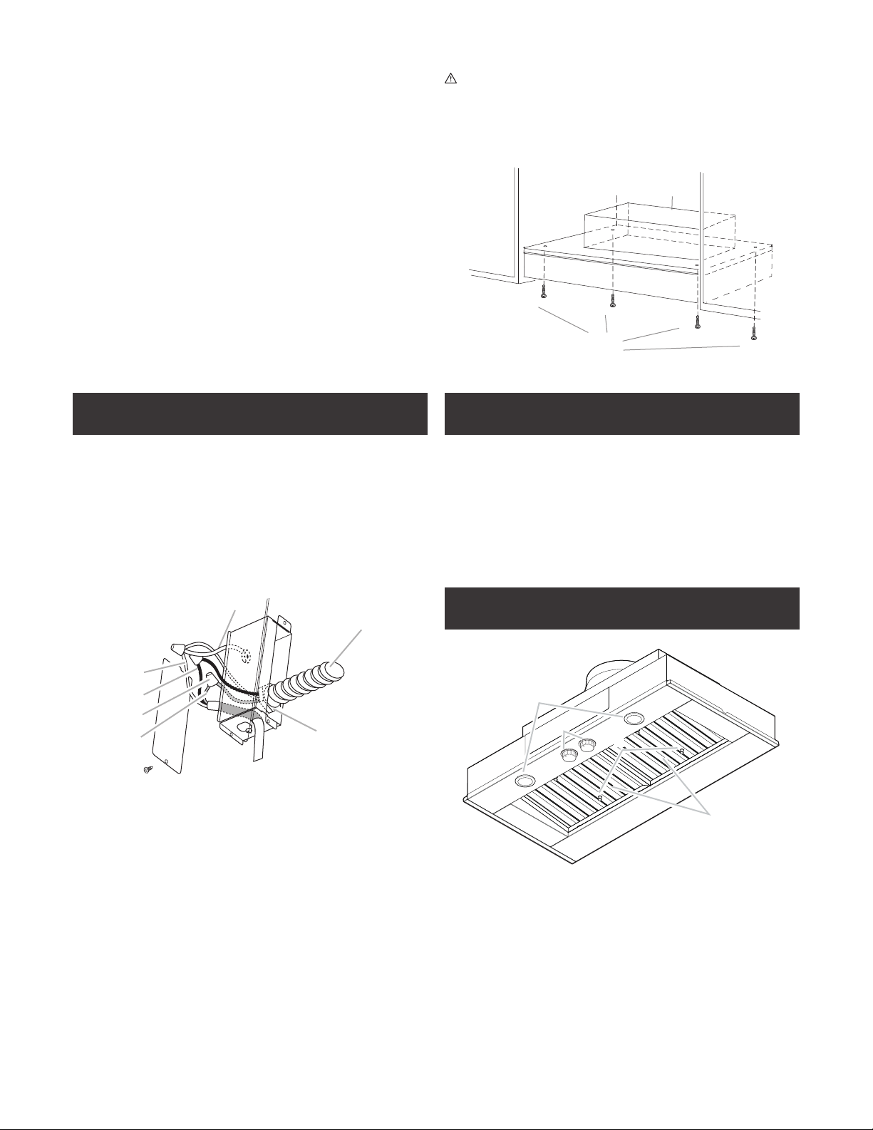
Description of the hood
1
4
3
2
1 Blower and light controls
2 LEDlamps
3 Greaselterhandle
4 Greaselter
Complete installation
Loading ...
Loading ...
Loading ...