Loading ...
Loading ...
Loading ...
9WWW.SENIXTOOLS.COM
INSTALL THE CHAIN BAR AND CHAIN
Disconnect the spark plug wire before performing
maintenance or assembly procedures.
Cutting edges on chain are sharp.
Use protective gloves when handling chain.
ALWAYS maintain proper chain tension. A loose chain
will increase the risk of kickback. A loose chain may
jump out of chain bar groove. This may injure operator
and damage chain. A loose chain will cause chain,
chain bar, and sprocket to wear rapidly. The chain
life of the saw chain mainly depends upon sufcient
lubrication and correct tensioning. Avoid tensioning the
chain if it is hot, as this will cause the chain to become
over tensioned when it cools down.
1. Place the saw body on a rm and level surface.
2. Using the supplied wrench, turn the bar adjustment
locking nut counter-clockwise to loosen it. Remove
the locking nut and cover.
5. Turn the chain tensioning screw clockwise to
preliminarily tighten the chain bar enough that it
stays in place. While holding the bar still, place the
cover back onto the saw. Make sure the tab properly
lines up with the slot on the body of the saw. Install
the locking nut. Using the supplied wrench, turn
the locking nut clockwise to tighten it. DO NOT
overtighten.
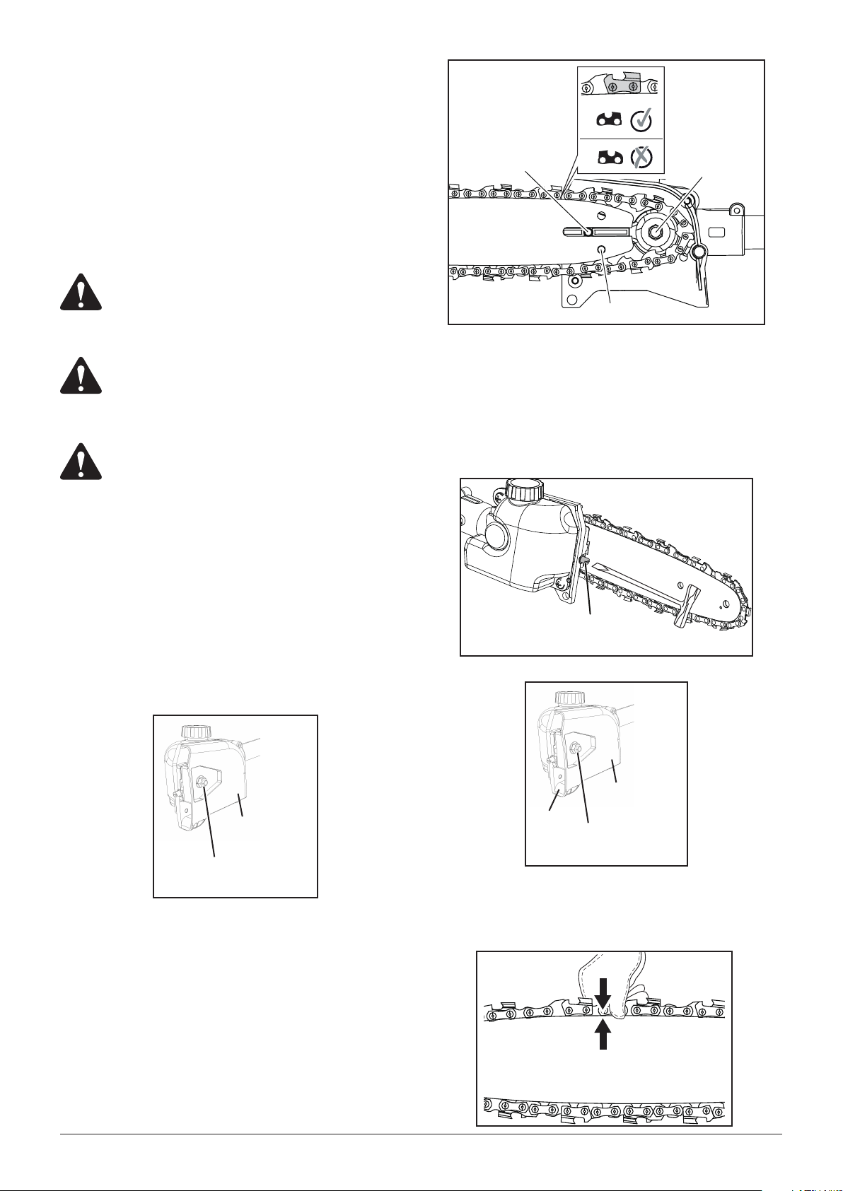
6. Check the chain tension by pulling the saw chain
away from the chain bar. A properly tensioned chain
should have roughly 1/8 inch (3 mm) of distance
between itself and the bar guide.
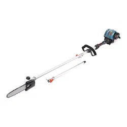
3. Wearing protective gloves, wrap the saw chain
around the chain bar, making sure that the teeth are
aimed in the direction of rotation. The chain should
be properly set in the slot running along the entire
outside edge of the chain bar.
4. Place the saw chain around the sprocket while lining
up the slot in the chain bar with the internal bolt at the
base of the saw and the chain tensioning pin in the
chain bar’s pin hole. The chain tensioning pin may
need adjustment to properly align with the hole in the
chain bar. Use a at-blade screwdriver to turn the
chain tensioning screw to adjust the location of the
pin until it ts in the chain bar.
WARNING:
WARNING:
WARNING:
Cover
Bar adjustment
locking nut
Cover
Bar adjustment
locking nut
Tab
turn to lock-out position. Remove cap and cardboard
spacer, if necessary.
3. Align the hole in the extension boom with the locator
pin on the coupler.
4. Install the extension tube into the coupler. Pull the
locator pin out and turn 1/4 turn clockwise to release.
Push the drive shaft until the locator pin locks into
place.
5. Tighten the clamping knob.
6. Following steps 1 to 5, install the lower drive shaft
assembly.
Sprocket
Chain Tensioning Pin
Internal Bolt
Chain
Tensioning
Screw
1/8” (3 mm)
Loading ...
Loading ...
Loading ...