Loading ...
Loading ...
Loading ...
14 15
ENGLISH
CAPACITANCE
1. Insert RED test lead into VΩµA jack
5
, and BLACK test lead into COM
jack
4
, and rotate function selector switch
2
to the Continuity/
Resistance/Capacitance/Diode-Test setting.
NOTE: The meter defaults to Continuity testing in this mode. To measure capacitance,
press the "SEL/NCV" button
12
repeatedly until nF appears on the display.
2. Remove power from circuit.
3. Measure capacitance by connecting test leads across the capacitor.
The meter will auto-range to display the measurement in the most
appropriate range.
OPERATING INSTRUCTIONS
Red leadBlack lead
DIODE TEST
1. Insert RED test lead into VΩµA jack
5
, and BLACK test lead into COM
jack
4
, and rotate function selector switch
2
to the Continuity/
Resistance/Capacitance/Diode-Test setting.
NOTE: The meter defaults to Continuity testing in this mode. Press the "SEL/
NCV" button
12
repeatedly until the diode icon appears on the display.
Touch test leads to diode. A reading of 200-800mV on display indicates
forward bias, "OL" indicates reverse bias. An open device will show "OL" in
both polarities. A shorted device will show approximately 0mV.
Red leadBlack lead
OPERATING INSTRUCTIONS
µA DC CURENT (LESS THAN 200 µA)
1. Insert RED test lead into VΩµA jack
5
, and BLACK test lead into COM
jack
4
, and rotate function selector switch
2
to the
DC μA setting. The "μA" and "DC" icons will appear on the display.
2. Remove power from circuit and open circuit at measurement point.
3. Connect test leads in series with the circuit.
4. Apply power to the circuit to take the measurement.
DO NOT
attempt to
measure more
than 200µA.
Red leadBlack lead
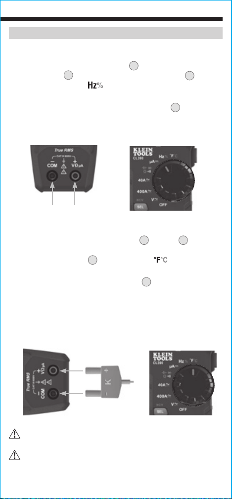
TEMPERATURE
1. Insert K-type thermocouple into the VΩµA
5
and COM
4
jacks
(observe polarity markings on thermocouple and meter), and rotate
function selector switch
2
to the Temperature setting.
NOTE: The meter defaults to Fahrenheit scale in this mode. To enter
Celsius scale, press the "SEL/NCV" button
12
once. Ensure that the
appropriate icon (either
°F
or
°C
) appears on the display.
2. To measure temperature, make contact between the
thermocouple tip and the object being measured. When
thermocouple tip and object are in thermal equilibrium, the
measurement on the display will stabilize.
Remove thermocouple before switching meter to other
measurement functions.
The thermocouple included with the original purchase
is suitable for temperatures below 446°F / 230°C only. To
measure higher temperatures, a K-type thermocouple
with the appropriate measurement range should be used.
OPERATING INSTRUCTIONS
FREQUENCY / DUTY-CYCLE
1. Insert RED test lead into VΩµA jack
5
and BLACK test lead
into COM jack
4
, and rotate function selector switch
2
to the
Frequency/Duty-Cycle
setting.
NOTE: The meter defaults to Frequency testing in this mode. To enter
Duty-Cycle testing mode, press the "SEL/NCV" button
12
once. Ensure
that the appropriate icon (either
Hz
or
%
) appears on the display.
2. Measure by connecting test leads across the circuit.
Red leadBlack lead
K-Type
Thermocouple
Loading ...
Loading ...
Loading ...