
Loading ...
Loading ...
Loading ...
12 13
OPERATING INSTRUCTIONS
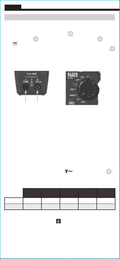
AC/DC VOLTAGE (LESS THAN 600V)
1. Insert RED test lead into VΩµA jack
5
, and BLACK test lead
into COM jack
4
, and rotate function selector switch
2
to the
V
setting for AC or DC measurements. The meter defaults to
AC measurement. To measure DC, press the SEL/NCV button
12
to toggle between AC and DC modes. The AC or DC icon on the
LCD indicates which mode is selected.
Apply test leads to the circuit to be tested to measure voltage.
The meter will auto-range to display the measurement in the most
appropriate range.
NOTE: If "–" appears on the LCD, this indicates negative polarity for
DC voltage.
NOTE: When in a voltage setting and the test leads are open,
readings of order mV may appear on the display. This is noise and
is normal. By touching the test leads together to close the circuit
the meter will measure zero volts.
NOTE: To access mV range for V AC
the "RANGE" button
8
must be used.
NOTE: When voltages in excess of 25V AC or 60V DC are measured
the hazardous voltage indicator
will be present on the display.
ENGLISH
Red leadBlack lead
Manual Mode Sequence
First
Press
Second
Press
Third
Press
Fourth
Press
Fifth
Press
AC Range 0-600V 0-420V 0-42V 0-4.2V 0-420mV
DC Range 0-42V 0-4.2V 0-420mV 0-600V 0-420V
CONTINUITY
1. Insert RED test lead into VΩµA jack
5
, and BLACK test lead
into COM jack
4
, and rotate function selector switch
2
to the
Continuity/Resistance/Capacitance/Diode-Test
setting.
NOTE: The meter defaults to Continuity testing in this mode. Ensure
that the Continuity Testing icon
is visible on the display. If not,
press the "SEL/NCV" button
12
repeatedly until the icon is shown.
2. Remove power from circuit.
3. Test for continuity by connecting conductor or circuit with test
leads. If resistance is measured less than 10Ω, an audible signal
will sound and display will show a resistance value indicating
continuity. If circuit is open display will show "OL".
DO NOT attempt to measure continuity on a live circuit.
OPERATING INSTRUCTIONS
Red leadBlack lead
RESISTANCE MEASUREMENTS
1. Insert RED test lead into VΩµA jack
5
, and BLACK test lead
into COM jack
4
, and rotate function selector switch
2
to the
Continuity/Resistance/Capacitance/Diode-Test
setting.
NOTE: The meter defaults to Continuity testing in this mode. Press
the "SEL/NCV" button
12
repeatedly until the resistance icon
appears on the display.
2. Remove power from circuit.
3. Measure resistance by connecting test leads to circuit. The
meter will auto-range to display the measurement in the most
appropriate range.
NOTE: When in a Resistance setting and the test leads are open
(not connected across a resistor), or when a failed resistor is under
test, the display will indicate "OL" This is normal.
DO NOT attempt to measure resistance on a live circuit.
Red leadBlack lead
Loading ...
Loading ...
Loading ...