
Loading ...
Loading ...
Loading ...
10 11
HOT WIRE
GROUND WIRE
LIVE
CABLE
NEUTRAL WIRE
ENGLISH
OPERATING INSTRUCTIONS
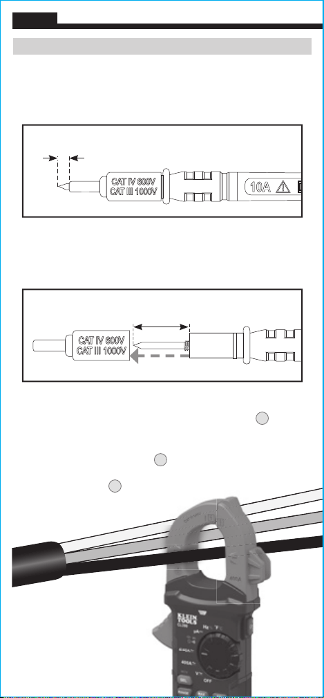
TESTING IN CAT III MEASUREMENT LOCATIONS
Ensure the test lead shield is pressed firmly in place. Failure to use
the CATIII / CATIV shield increases arc-flash risk.
TESTING IN CAT II MEASUREMENT LOCATIONS
CAT III / CAT IV shields may be removed for CAT II locations. This
will allow testing on recessed conductors such as standard wall
outlets. Take care not to lose the shields.
0.7" (18 mm)
5/32"
(4 mm)
OPERATING INSTRUCTIONS
To measure current:
1. Rotate the Function Selector switch
2
to the 400A setting.
2. Place clamp around wire. The current
measurement will be shown in the display.
NOTE: The meter defaults to AC measurement. Press the SEL/NCV
button to toggle between AC and DC modes. The AC or DC icon on
the display indicates which mode is selected.
NOTE: If the measurement is less than 40A, rotate the Function
Selector switch
2
to the 4/40A setting for improved resolution.
NOTE: If non-zero values are displayed prior to measuring in DC
current mode, a DC zero offset correction is required. With meter in
DC current mode, press the REL/ZERO button
8
to activate the DC
current ZERO function.
ZERO
icon will be present on the display.
Subsequent DC current measurements automatically subtract the
offset correction for improved accuracy. Press REL/ZERO button
8
to return to normal measuring mode.
NOTE: Do not use DC current function if the Magnetic Hanger
accessory is attached to the back of the meter. Interferences from the
magnet can lead to inaccurate measurements.
Disconnect test leads when measuring with the clamp.
AC/DC CURRENT (LESS THAN 400A)
AC Current is measured by pressing the clamp trigger
10
to open
the clamp and placing it around a current-carrying wire. When
measuring, care should be taken to ensure that the clamp is
completely closed with trigger
10
fully released, and that the wire
passes perpendicularly through the center of the clamp in line with
the arrow markings
11
.
Loading ...
Loading ...
Loading ...