1
Español 15 • Français 29 • Русский 43 • Deutsch 57
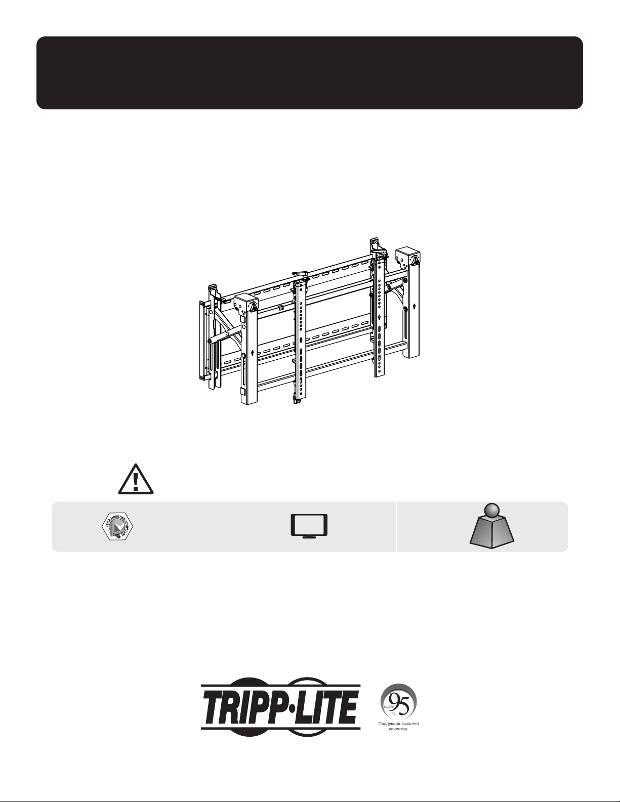
Owner’s Manual
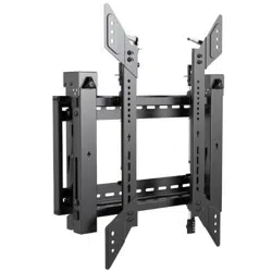
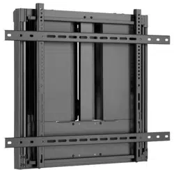
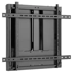
Landscape Video Wall
with Security
1111 W. 35th Street, Chicago, IL 60609 USA • tripplite.com/support
Copyright © 2021 Tripp Lite. All rights reserved.
WARRANTY REGISTRATION
Register your product today and be
automatically entered to win an ISOBAR
®
surge protector in our monthly drawing!
tripplite.com/warranty
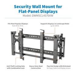
CAUTION: DO NOT EXCEED MAXIMUM LISTED WEIGHT CAPACITY. SERIOUS INJURY OR PROPERTY DAMAGE MAY OCCUR!
200x200/300x300
400x200/400x400
600x400
70"
MAX
154 lb.154 lb.
(70 kg)(70 kg)
RATEDRATED
Model: DWMSCL4570VW

2
Important Safety Instructions
Warranty and Product Registration
CAUTION
• Read the entire instruction manual before you start assembly and installation. Do not begin installation until you have
read and understood all the instructions and warnings contained in this installation sheet. If you have questions about
any of the instructions or warnings, contact Tripp Lite Support.
• Use with products heavier than the rated weights indicated may result in instability, causing possible injury.
• Mounts must be attached as specified in these instructions. Improper installation may result in damage or serious
personal injury.
• Safety gear and proper tools must be used. This product should only be installed by professionals.
• Ensure the supporting surface will safely support the combined weight of the equipment and all attached hardware and
components.
• Use the mounting screws provided, tighten them firmly, but DO NOT OVERTIGHTEN the mounting screws. Overtightening
can cause damage to the items. This greatly reduced their holding power.
• This product contains small items that could be a choking hazard if swallowed. Keep these items away from children.
• This product is intended for indoor use only. Using this product outdoors could lead to product failure and personal injury.
• Check that the bracket is secure and safe to use at regular intervals (at least every three months).
5-Year Limited Warranty
Seller warrants this product, if used in accordance with all applicable instructions, to be free from original defects in material and workmanship for a period of
5 years from the date of initial purchase. If the product should prove defective in material or workmanship within that period, Seller will repair or replace the
product, at its sole discretion.
THIS WARRANTY DOES NOT APPLY TO NORMAL WEAR OR TO DAMAGE RESULTING FROM ACCIDENT, MISUSE, ABUSE OR NEGLECT. SELLER MAKES NO
EXPRESS WARRANTIES OTHER THAN THE WARRANTY EXPRESSLY SET FORTH HEREIN. EXCEPT TO THE EXTENT PROHIBITED BY APPLICABLE LAW, ALL IMPLIED
WARRANTIES, INCLUDING ALL WARRANTIES OF MERCHANTABILITY OR FITNESS, ARE LIMITED IN DURATION TO THE WARRANTY PERIOD SET FORTH ABOVE;
AND THIS WARRANTY EXPRESSLY EXCLUDES ALL INCIDENTAL AND CONSEQUENTIAL DAMAGES. (Some states do not allow limitations on how long an implied
warranty lasts, and some states do not allow the exclusion or limitation of incidental or consequential damages, so the above limitations or exclusions may not
apply to you. This warranty gives you specific legal rights, and you may have other rights which vary from jurisdiction to jurisdiction.)
WARNING: The individual user should take care to determine prior to use whether this device is suitable, adequate or safe for the use intended. Since
individual applications are subject to great variation, the manufacturer makes no representation or warranty as to the suitability or fitness of these devices for
any specific application.
PRODUCT REGISTRATION
Visit tripplite.com/warranty today to register your new Tripp Lite product. You’ll be automatically entered into a drawing for a chance to win a FREE Tripp Lite
product!*
* No purchase necessary. Void where prohibited. Some restrictions apply. See website for details.
Tripp Lite has a policy of continuous improvement. Specifications are subject to change without notice. Images may differ slightly from actual products.

Package P
Package M
Package W
3
Component Checklist
IMPORTANT: Ensure you have received all parts according to the component checklist prior to installing.
If any parts are missing or faulty, visit tripplite.com/support for service.
B
Pop-Out Module(x1)
A
Wall Plate (x1)
M-A
M5x14 (x4)
M-F
Washer (x4)
M-B
M6x14 (x4)
M-G
Small Spacer (x8)
M-H
Large Spacer (x4)
M-C
M8x20 (x4)
M-D
M6x30 (x4)
M-E
M8x30 (x4)
D
Anti-Skid Block (x2)
C
Adapter Bracket (x2)
E
Plastic Locking Piece (x2)
F
Hex Key (x1)
G
Lock (x1)
W-A
ST6.3x55 (x6)
W-B
Concrete Anchor (x6)
W-C
D6 Washer (x6)

4
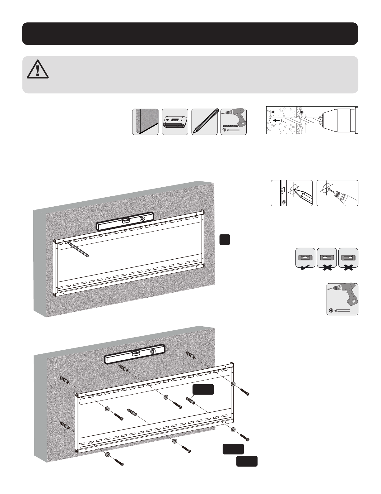
1. Solid Brick and Concrete Wall Mounting
Mark the exact
location of the
mounting holes.
Screw the wall
mount onto
the wall.
Drill pilot holes
1
2
95 mm95 mm
(3.7")(3.7")
2.4"
(60 mm)
Ø 3/8"
(Ø 10 mm)
W-B
W-C
W-A
A
WARNING
Installers must verify that the supporting surface will safely support the combined weight of the equipment and
all attached hardware and components.

5
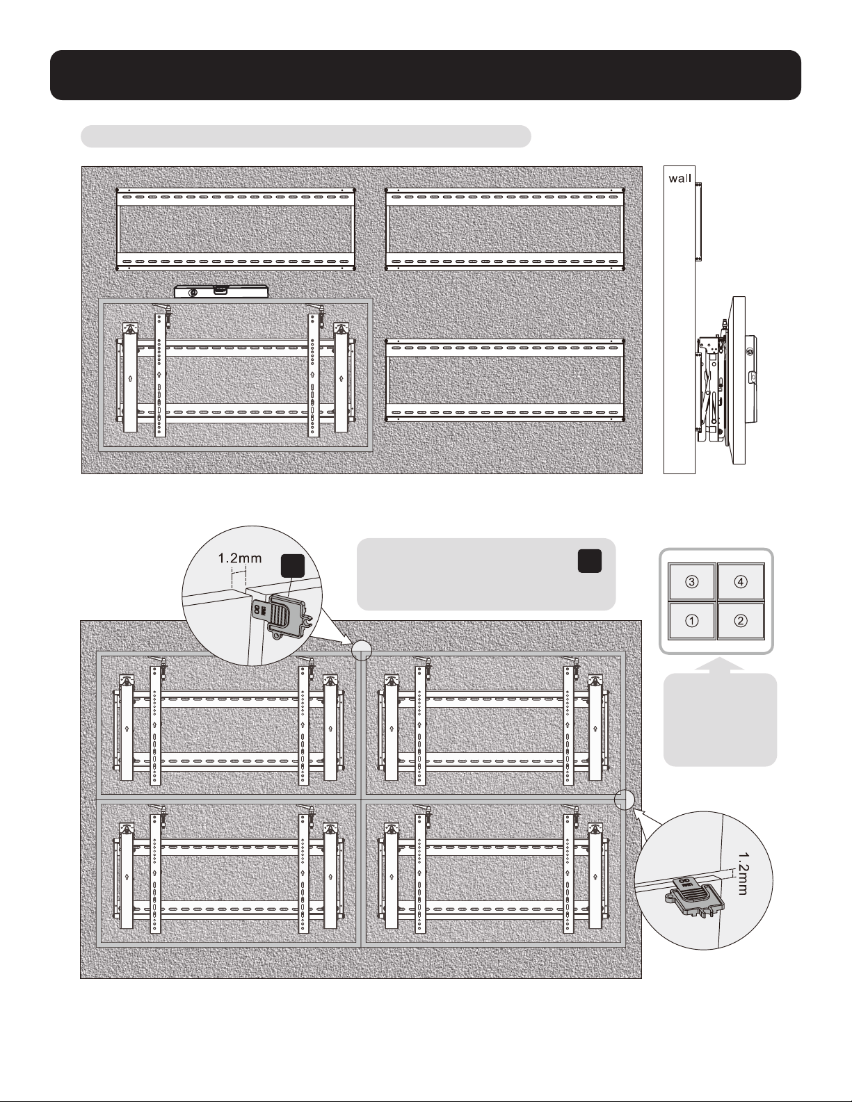
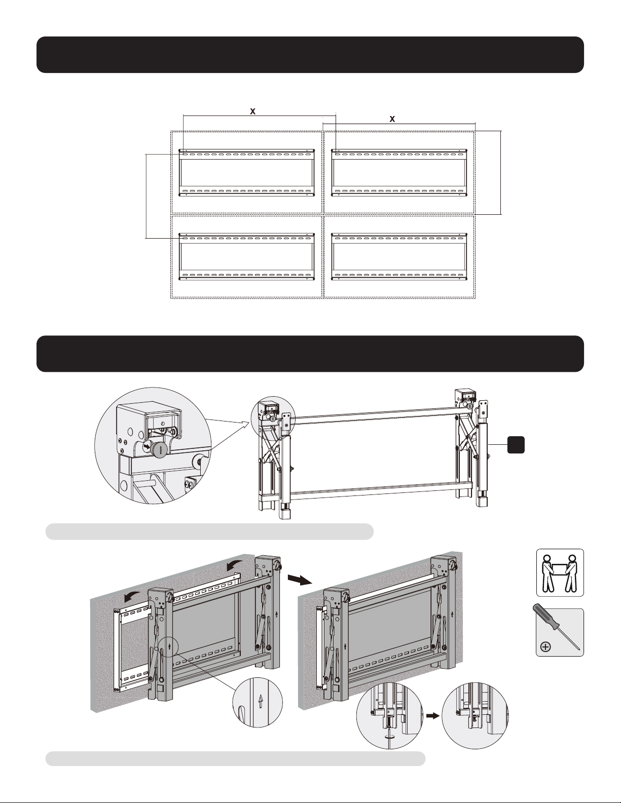
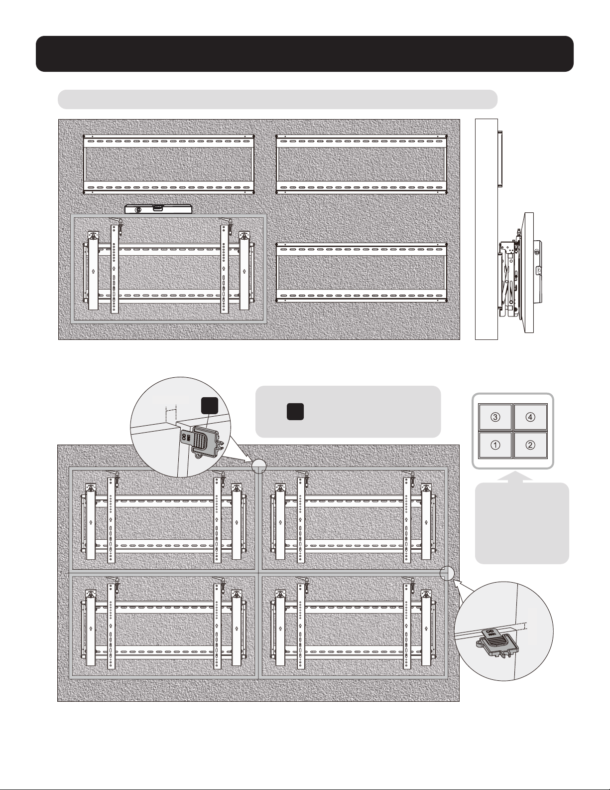
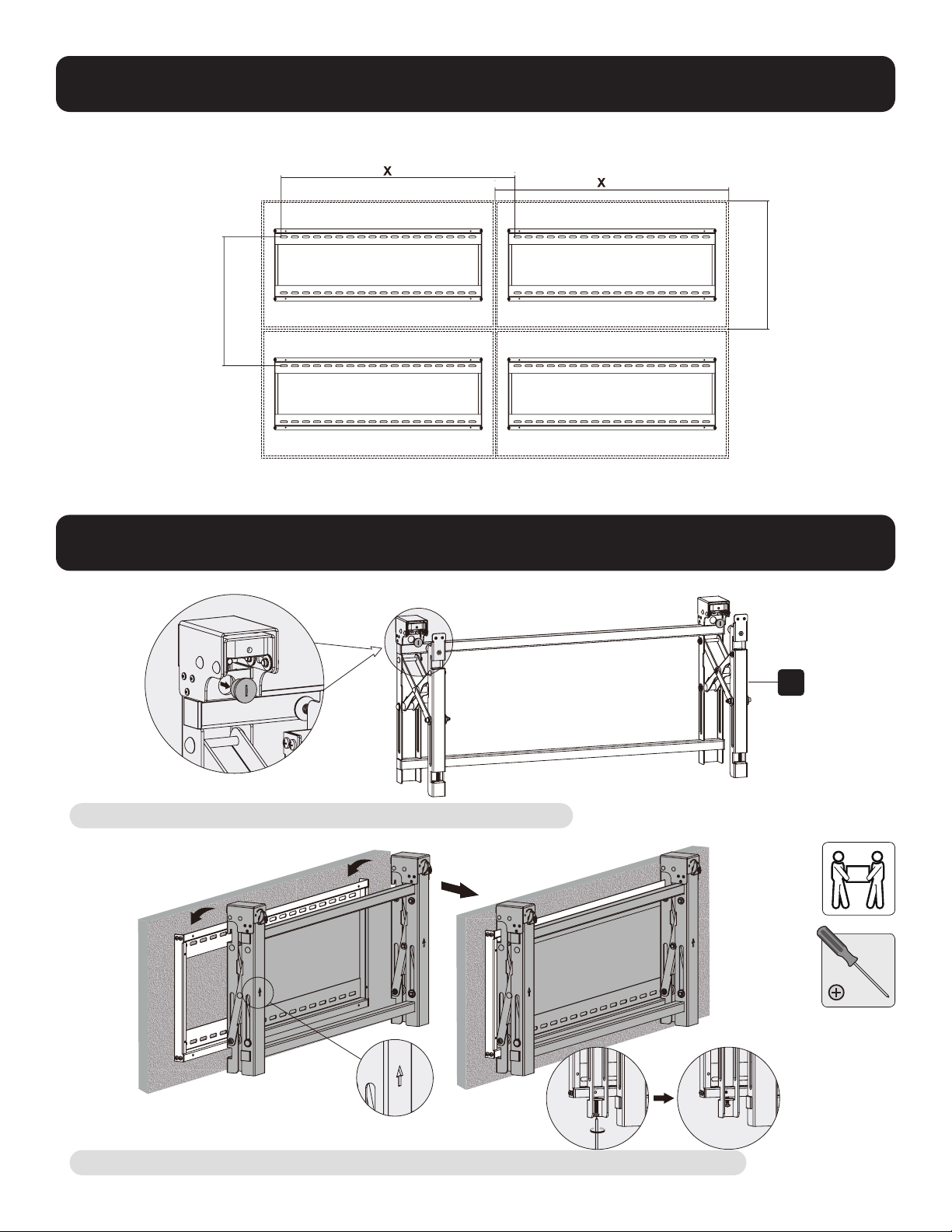
2. Video Wall Installation (mounting space as shown below)
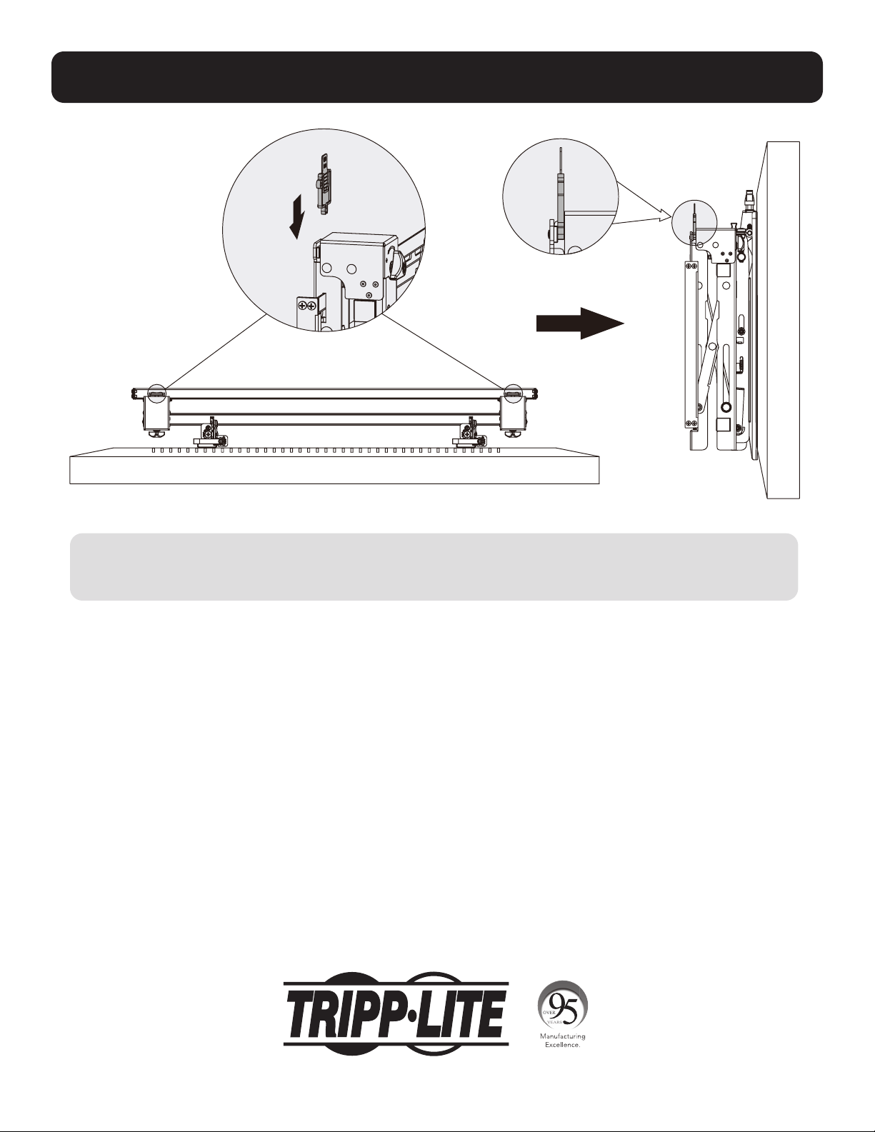
3. Installing the Pop-Out Module
Remove caps before installing the pop-out module.
Hang the pop-up module onto the wall plate. Secure it by tightening both screws.
B
Y = 0.2" (5 mm)
Y = 0.2" (5 mm)
X=Length of display Y=height of display

6
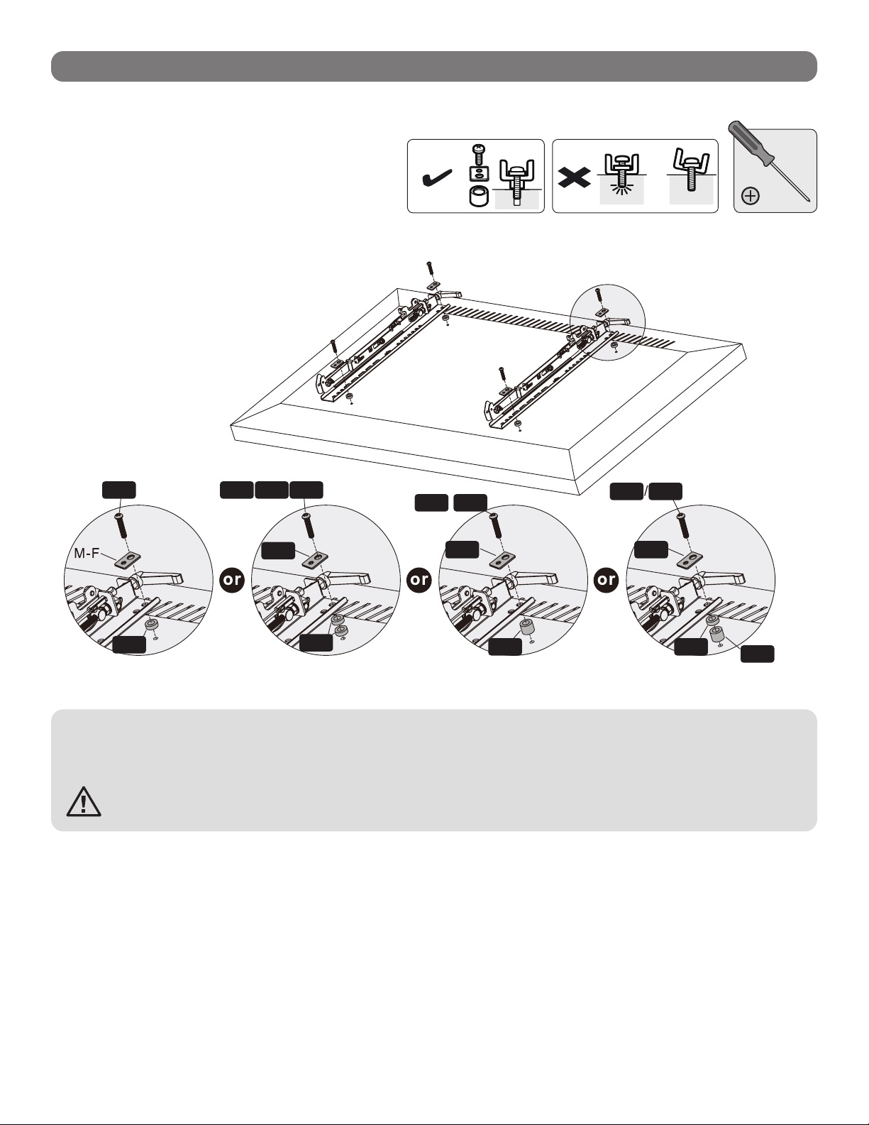
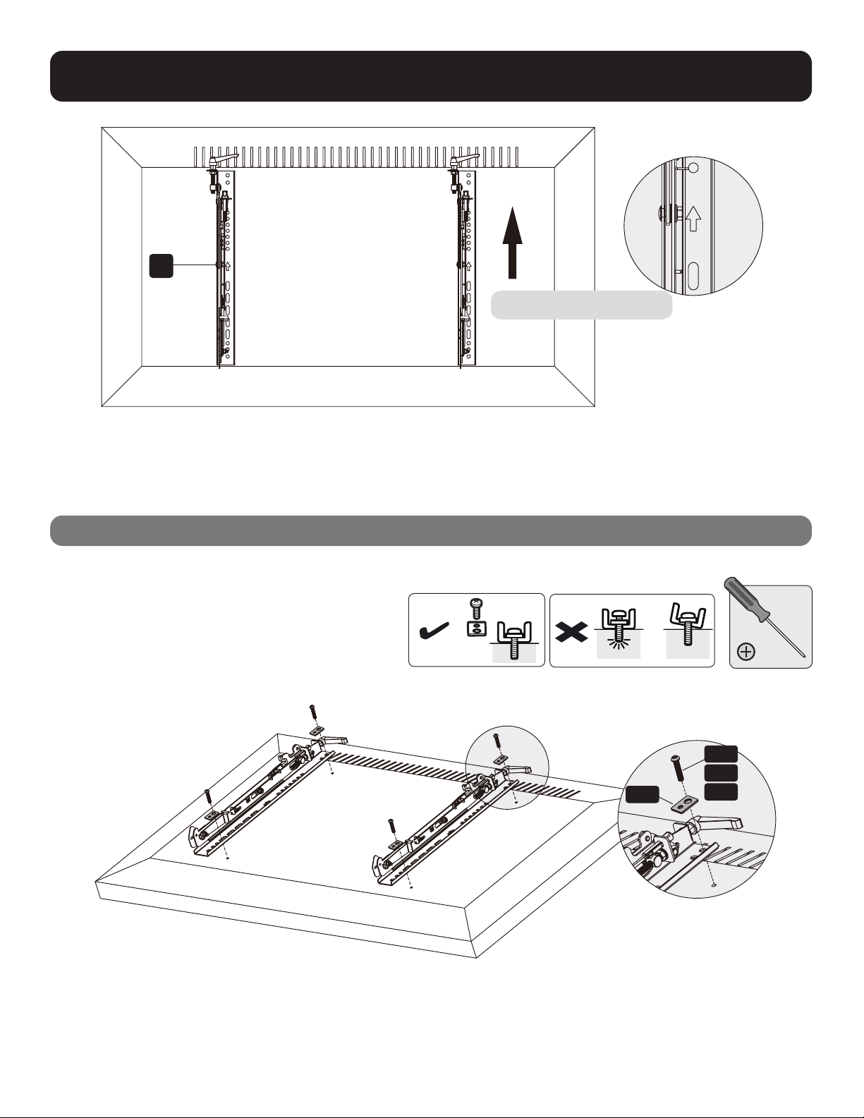
4. Installing the Adapter Brackets
4.1 For Flat-Back Screens
C
TV
TV
TV
M-A
M-B
M-C
M-F
Top of the display

7
4.2 For Bump-Out or Recessed-Back Screens
Notes:
• Choose the appropriate screws, washers and spacers (if necessary) according to the type of screen.
• Position the adapter brackets as close as possible to the center of the display.
• Screw the adapter brackets onto the display.
Tighten all screws but do not overtighten.
TV
TV
TV
M-H
M-H M-G
M-G
M-G
M-FM-F
M-F
M-D
M-C
M-E
M-D M-E
M-DM-C M-E

8
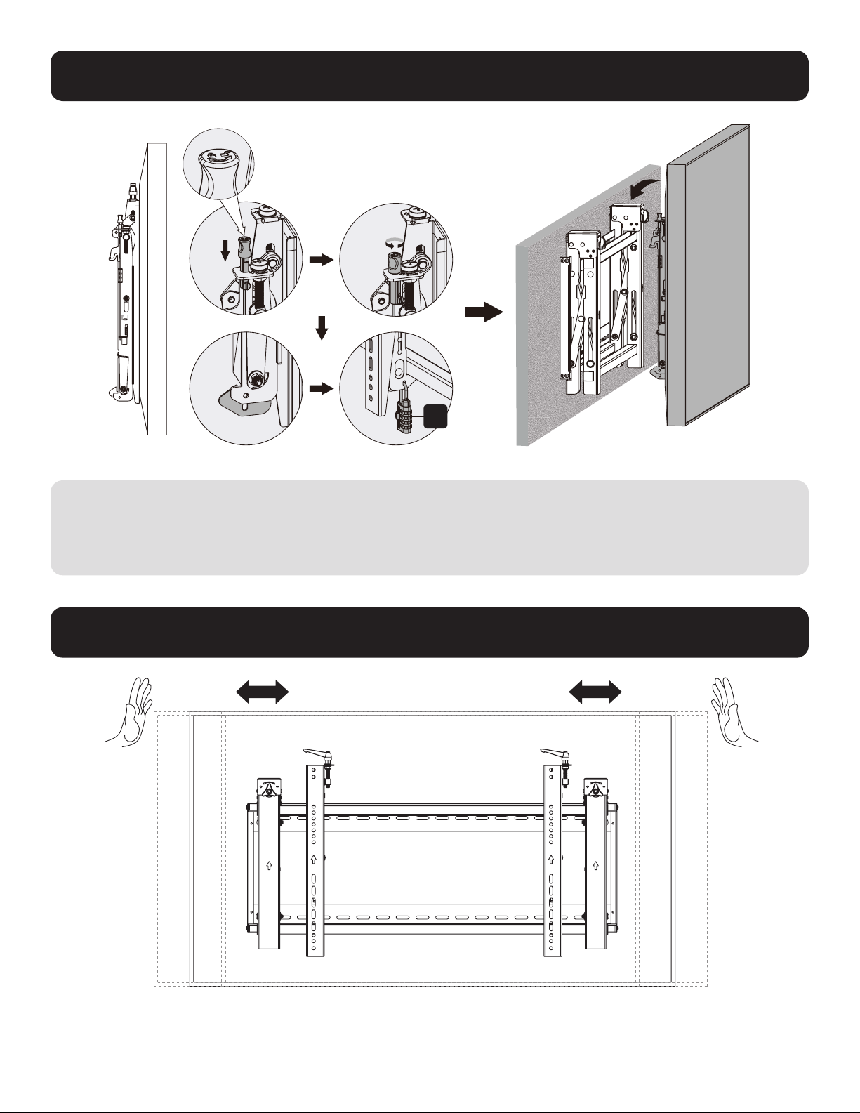
5. Hooking the Display onto the Pop-Out Module
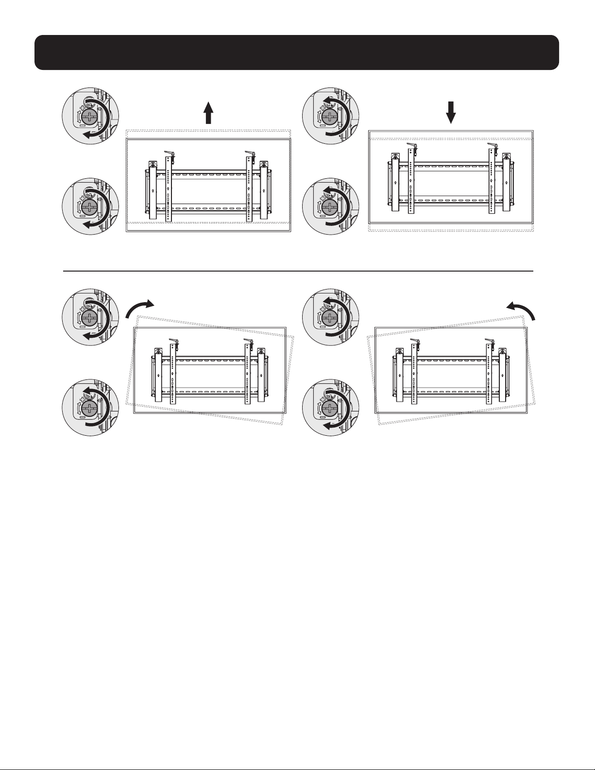
6. Adjustment
Notes:
• Before hooking the display, ensure the knobs are rotated to the unlock position.
• Lift the display carefully and hook it onto the pop-out module. Rotate the knobs to the lock position to secure the display.
• Use the lock to prevent the display from being removed from the mount.
Push the display left or right
for fast alignment.
G

9
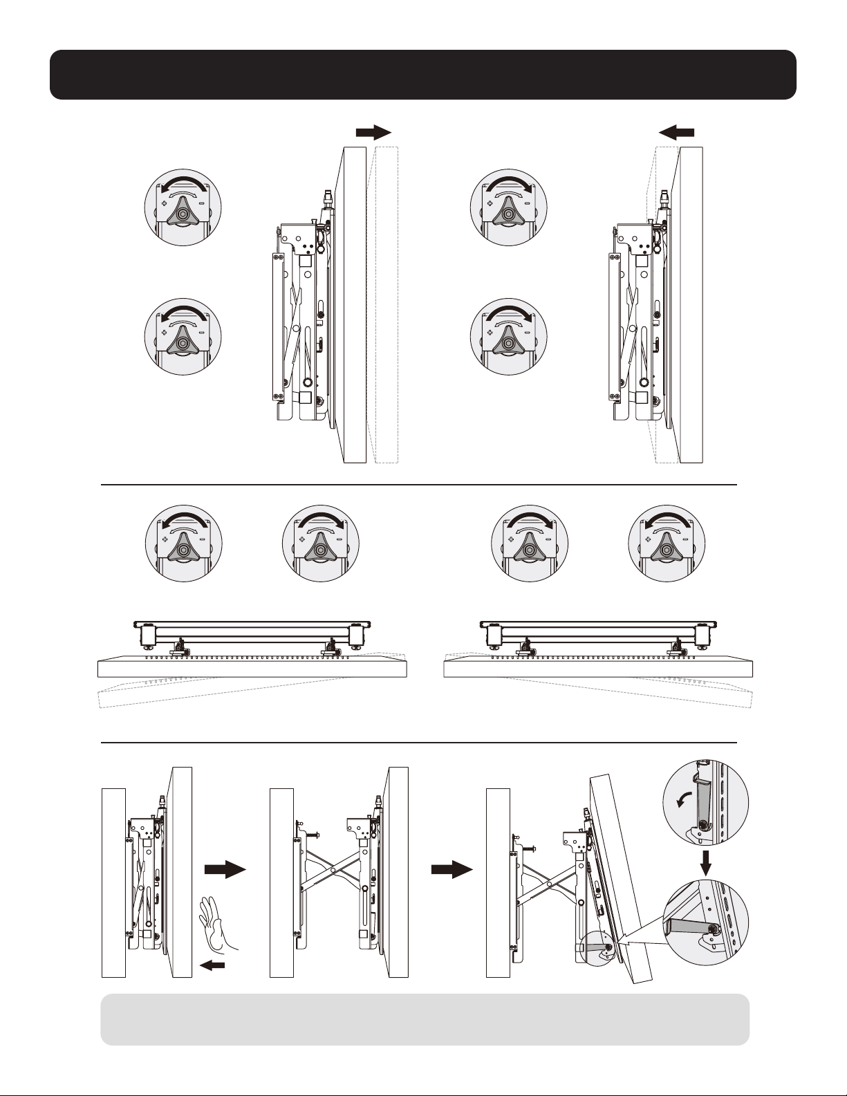
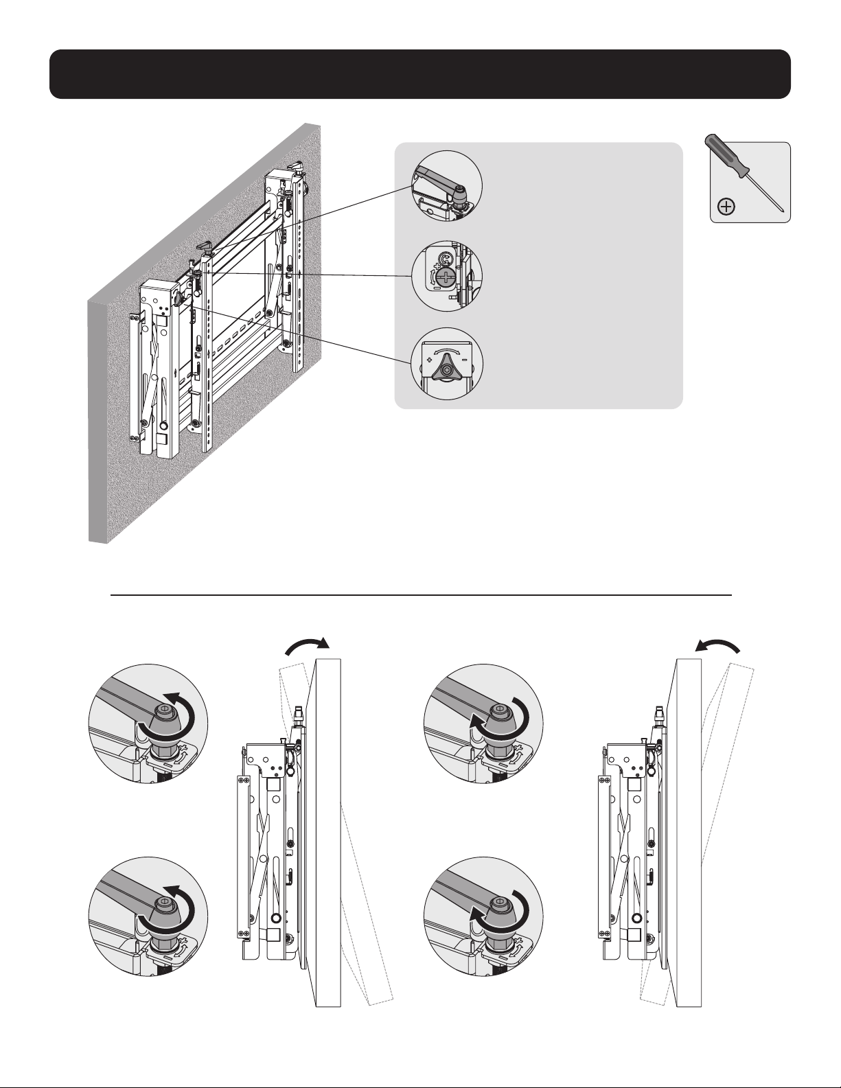
6. Adjustment
Handles for tilt adjustment
Screws for up-and-down
micro-adjustments
Knobs for in-and-out
micro-adjustments
Left Left
Right Right

10
6. Adjustment
Left
Left
Left
Left
Right
Right
Right
Right

11
6. Adjustment
To pop out the display, push it inward and then release it.
Kickstands provide tilt access for easy cable management and maintenance.
Left
Left Left
Left
Right
Right Right
Right
wall wall wall
12
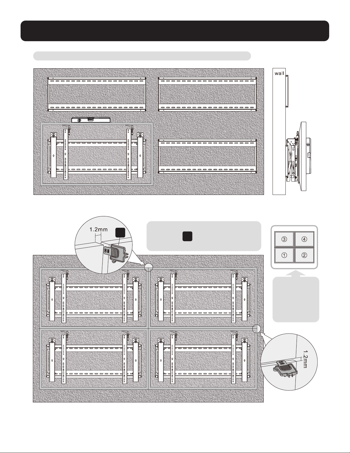
7. Level the Displays
Adjust the display to keep it level in vertical and horizontal directions.
Note: Use the plastic locking piece
E
to measure and keep a 1.2 mm
gap between displays.
E
Note: Install
and adjust
displays in the
numerical
order shown.

13
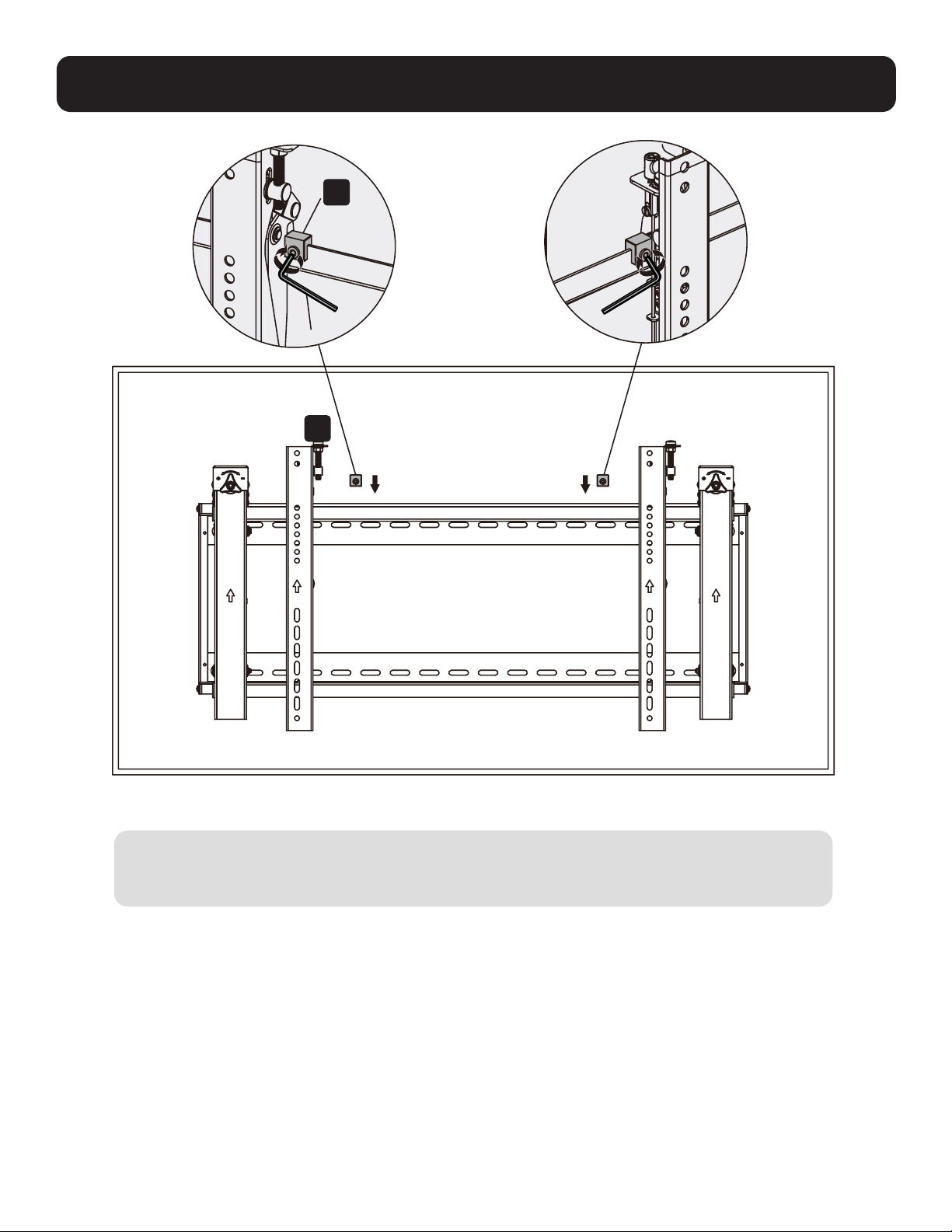
8. Fixing the Bracket Positions with the Anti-Skid Blocks
D
Install both of the anti-skid blocks as close to the adapter brackets as possible.
Tighten screws on the anti-skid blocks using an hex key to prevent the display from moving.
F
14
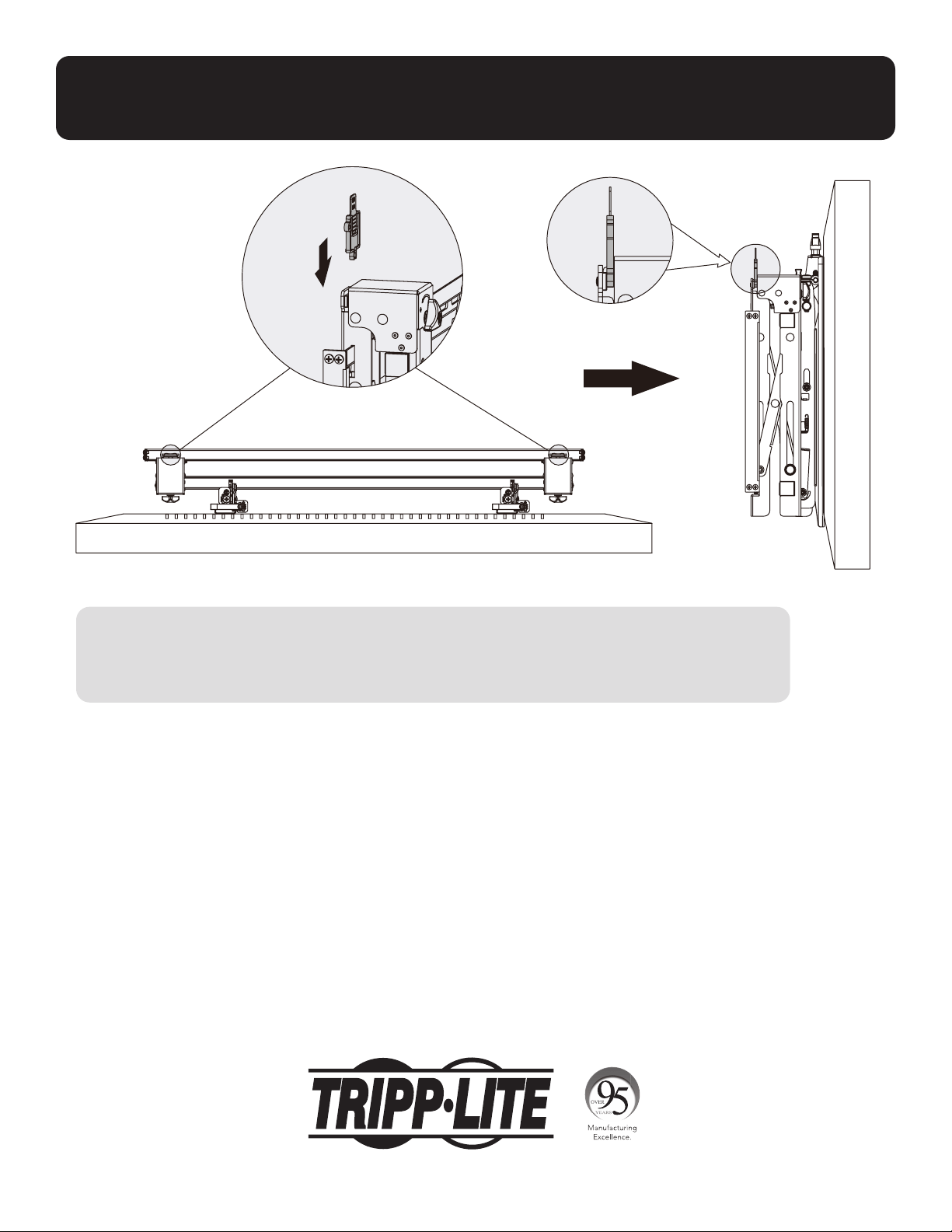
9. Lock the Pop-Out Module with the Plastic Locking Pieces
Maintenance
• Check that the bracket is secure and safe to use at regular intervals (at least every three months).
• Please contact Tripp Lite if you have any questions.
1111 W. 35th Street, Chicago, IL 60609 USA • tripplite.com/support
21-06-104 933F0F_RevA

15
MÁS DE
AÑOS
English 1 • Français 29 • Русский 43 • Deutsch 57
Manual del Propietario
Muro de Video horizontal
con Seguridad
1111 W. 35th Street, Chicago, IL 60609, EE. UU. • tripplite.com/support
Copyright © 2021 Tripp Lite. Todos los derechos reservados.
PRECAUCIÓN: NO EXCEDA LA CAPACIDAD DE CARGA MÁXIMA INDICADA. ¡PUEDEN OCURRIR LESIONES GRAVES
O DAÑOS A LA PROPIEDAD!
200x200 / 300x300
400x200 / 400x400
600 x 400
70"
MÁXIMO
70 kg70 kg
[154 lb][154 lb]
CLASIFICADOCLASIFICADO
Modelo: DWMSCL4570VW

16
Instrucciones de Seguridad Importantes
Garantía
PRECAUCIÓN
• Lea todo el manual de instrucciones antes de iniciar el ensamble y la instalación. No inicie la instalación hasta que haya leído y
entendido todas las instrucciones y advertencias contenidas en esta hoja de instalación. Si usted tiene preguntas sobre cualquiera
de las instrucciones o advertencias, póngase en contacto con Soporte de Tripp Lite.
• El uso con productos más pesados que los pesos nominales especificados puede resultar en inestabilidad y dar lugar a posibles
lesiones.
• Los soportes deben instalarse como se especifica en estas instrucciones. La instalación incorrecta puede causar daños o lesiones
personales graves.
• Se deben usar equipos de seguridad y herramientas adecuadas. Este producto debe ser instalado únicamente por profesionales.
• Asegure que la superficie de apoyo soporte con seguridad el peso combinado de todo el hardware y componentes instalados.
• Use los tornillos de instalación suministrados. Apriételos firmemente, pero no los APRIETE EN EXCESO. Si los aprieta en exceso,
podría dañarlos. Esto reduce enormemente su capacidad de carga.
• Este producto contiene pequeñas piezas que pueden ser un riesgo de asfixia si se ingieren. Mantenga estas piezas fuera del
alcance de los niños.
• Este producto está diseñado para usarse solo en interiores. Usar este producto en exteriores podría derivar en fallas del producto
y lesiones personales.
• Compruebe a intervalos regulares (al menos trimestralmente) que el soporte esté bien instalado y sea seguro para usarse.
Garantía Limitada por 5 Años
El vendedor garantiza este producto, si se usa de acuerdo con todas las instrucciones aplicables, está libre de defectos en cuanto a materiales y mano de
obra por un período de 5 años a partir de la fecha de compra inicial. Si el producto resulta defectuoso en cuanto a materiales o mano de obra dentro de ese
período, el vendedor reparará o reemplazará el producto a su entera discreción.
ESTA GARANTÍA NO SE APLICA AL DESGASTE NORMAL O A LOS DAÑOS QUE RESULTEN DE ACCIDENTES, USO INCORRECTO, USO INDEBIDO O NEGLIGENCIA.
EL VENDEDOR NO OTORGA GARANTÍAS EXPRESAS DISTINTAS A LA ESTIPULADA EN EL PRESENTE. SALVO EN LA MEDIDA EN QUE LO PROHÍBAN LAS
LEYES APLICABLES, TODAS LAS GARANTÍAS IMPLÍCITAS, INCLUIDAS TODAS LAS GARANTÍAS DE COMERCIALIZACIÓN O IDONEIDAD, ESTÁN LIMITADAS EN
CUANTO A DURACIÓN AL PERÍODO DE GARANTÍA ESTABLECIDO; ASIMISMO, ESTA GARANTÍA EXCLUYE EXPRESAMENTE TODOS LOS DAÑOS INCIDENTALES
E INDIRECTOS. (Algunos estados no permiten limitaciones en cuanto a la duración de una garantía y algunos estados no permiten la exclusión o limitación
de daños incidentales o indirectos, de modo que es posible que las limitaciones anteriores no se apliquen a usted. Esta garantía le otorga derechos legales
específicos y es posible que le asistan otros derechos que pueden variar de una jurisdicción a otra).
ADVERTENCIA: antes de usarlo, cada usuario debe tener cuidado al determinar si este dispositivo es adecuado o seguro para el uso previsto. Ya que las
aplicaciones individuales están sujetas a gran variación, el fabricante no garantiza la adecuación de estos dispositivos para alguna aplicación específica.
Tripp Lite tiene una política de mejora continua. Las especificaciones están sujetas a cambio sin previo aviso. Las imágenes pueden diferir ligeramente de
los productos reales.

Paquete P
Paquete M
Paquete W
17
Lista de Comprobación de Componentes
IMPORTANTE: Antes de proceder a instalar, asegúrese de haber recibido todas las partes de acuerdo con la lista de comprobación
de componentes. Si faltase alguna parte o estuviese dañada, visite tripplite.com/support para solicitar servicio.
B
Módulo Emergente (x1)
A
Placa de Pared
(x1)
M-A
M5x14 (x4)
M-F
Arandela (x4)
M-B
M6x14 (x4)
M-G
Espaciador Pequeño (x8)
M-H
Espaciador Grande (x4)
M-C
M8x20 (x4)
M-D
M6x30 (x4)
M-E
M8x30 (x4)
D
Bloque Antideslizante (x2)
C
Soporte Adaptador (x2)
E
Pieza de Bloqueo de Plástico (x2)
F
Llave Hexagonal (x1)
G
Cerradura (x1)
W-A
ST6.3x55 (x6)
W-B
Taquete (x6)
W-C
Arandela D6 (x6)

18
1. Instalación sobre Pared de Ladrillo Sólido y Concreto
Marque la posición
exacta de los
orificios de
instalación
Atornille el
soporte de
pared a la
pared.
Perfore los
orificios piloto
1
2
95 mm95 mm
(3.7")(3.7")
60 mm
[2.4"]
Ø 10 mm
[Ø 3/8"]
W-B
W-C
W-A
A
ADVERTENCIA:
Los instaladores deben verificar que la superficie de apoyo soporte con seguridad el peso combinado del
equipo y de todo el hardware y componentes instalados.

19
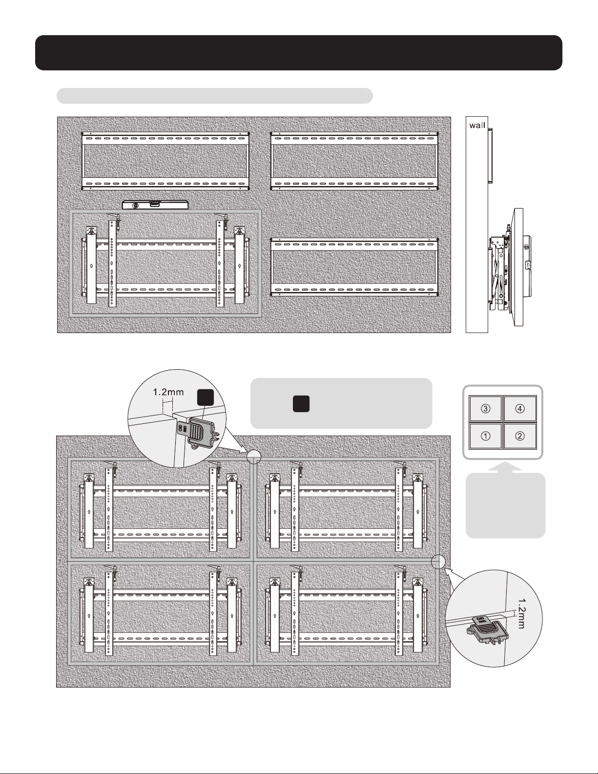
2. Instalación en Muro de Video (el espacio de instalación
debe ser como se muestra a continuación)
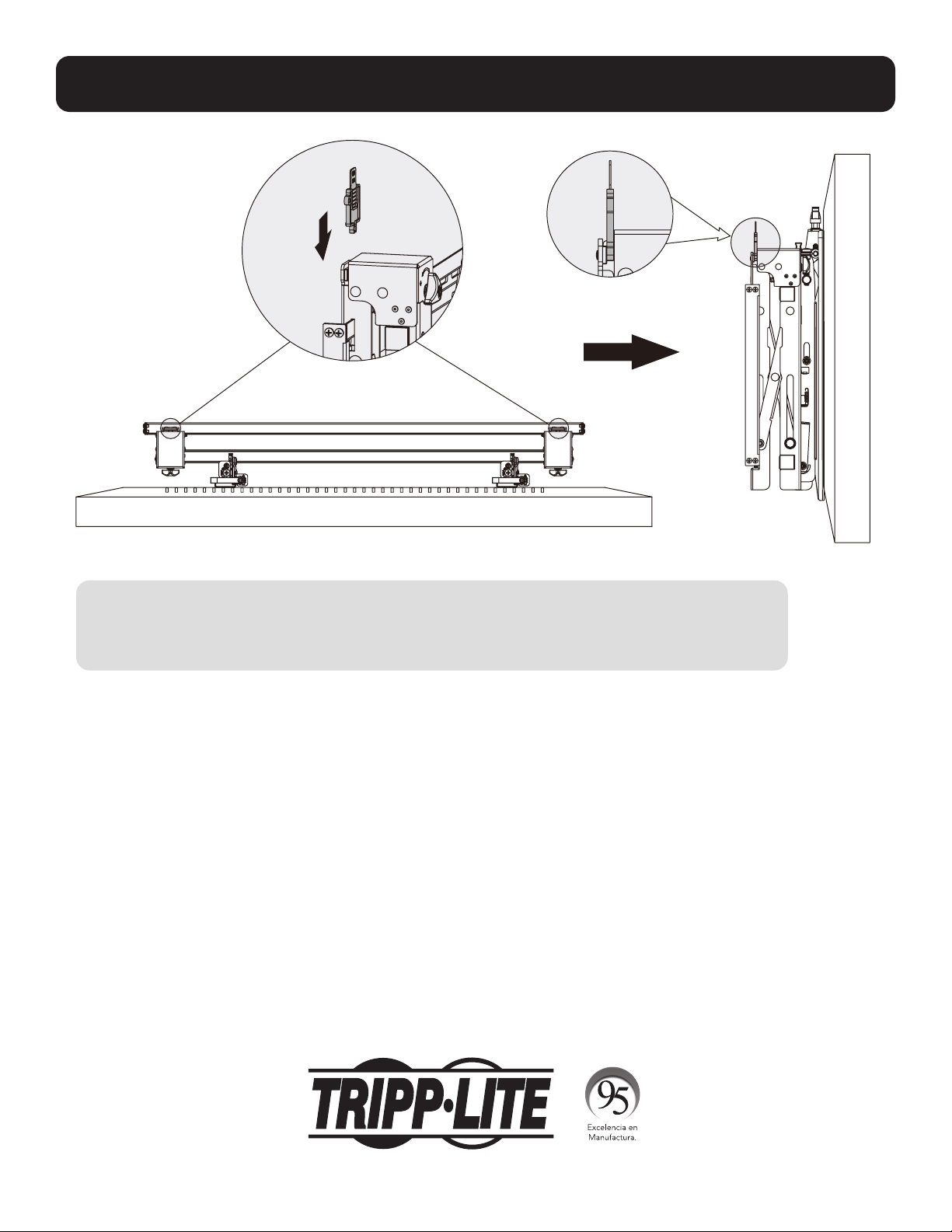
3. Instalación del Módulo Emergente
Retire los tapones antes de instalar el módulo emergente.
Cuelgue el módulo emergente en la placa de pared. Asegúrelo apretando ambos tornillos.
B
Y = 5 mm [0.2"]
Y = 5 mm [0.2"]
X=longitud de la pantalla Y=altura de la pantalla

20
4. Instalación de los Soportes Adaptadores
4.1 Para Pantallas de Respaldo Plano
C
TV
TV
TV
M-A
M-B
M-C
M-F
Parte superior
de la pantalla

21
4.2 Para Pantallas Bump Out o con Parte Posterior Cóncava
Notas:
• Elija los tornillos, arandelas y espaciadores (si fueran necesarios) apropiados de acuerdo con el tipo de pantalla.
• Coloque los soportes adaptadores tan cerca como sea posible al centro de la pantalla.
• Atornille los soportes adaptadores a la pantalla.
Apriete todos los tornillos pero no en exceso.
TV
TV
TV
M-H
M-H M-G
M-G
M-G
M-FM-F
M-F
M-D
M-C
M-E
M-D M-E
M-DM-C M-E

22
5. Enganche la Pantalla en el Módulo Emergente
6. Ajuste
Notas:
• Antes de enganchar la pantalla, asegúrese de que las perillas estén giradas a la posición de desbloqueo.
• Levante cuidadosamente la pantalla y engánchela en el módulo emergente. Gire las perillas a la posición de bloqueo
para asegurar la pantalla.
• Use el candado para evitar que la pantalla sea retirada del soporte.
Para la rápida alineación, empuje la
pantalla a la izquierda o a la derecha.
G

23
6. Ajuste
Manijas para el ajuste de
inclinación.
Tornillos para microajustes
hacia arriba y hacia abajo
Perillas para microajustes
de entrada y salida
Izquierda
Izquierda
Derecha Derecha

24
6. Ajuste
Izquierda
Izquierda
Izquierda
Izquierda
Derecha
Derecha
Derecha
Derecha

25
6. Ajuste
Para salir de la pantalla, empújela hacia adentro y suéltela.
Los soportes de apoyo proporcionan acceso de inclinación para fácil administración del cableado y mantenimiento.
Izquierda
Izquierda
Izquierda
Izquierda
Derecha
Derecha
Derecha
Derecha
pared pared pared
26
7. Nivele las Pantallas
Ajuste la pantalla para mantenerla nivelada en la direcciones vertical y horizontal.
Nota: Use la pieza de bloqueo de
plástico
E
para medir y mantener una
separación de 1.2 mm entre pantallas.
E
Nota: Instale y
ajuste pantallas
en el orden
numérico
mostrado.

27
8. Fijación de las Posiciones del Soporte con los Bloques Antideslizantes
D
Instale ambos bloques antideslizantes tan cerca de los soportes adaptadores como sea posible.
Apriete los tornillos en los bloques anti-deslizantes usando una llave hexagonal para evitar que la
pantalla se mueva.
F
28
MÁS DE
AÑOS
9. Bloquee el Módulo Emergente con las Piezas de Bloqueo de Plástico
Mantenimiento
• Compruebe a intervalos regulares (al menos trimestralmente) que el soporte esté bien instalado y sea
seguro para usarse.
• Si tiene alguna pregunta, póngase en contacto con Tripp Lite.
1111 W. 35th Street, Chicago, IL 60609, EE. UU. • tripplite.com/support
21-06-104 933F0F_RevA

29
English 1 • Español 15 • Русский 43 • Deutsch 57
Manuel de l'utilisateur
Montage mural vidéo
paysage avec sécurité
1111 W. 35th Street, Chicago, IL 60609 USA • tripplite.com/support
Droits d'auteur © 2021 Tripp Lite. Tous droits réservés.
MISE EN GARDE : NE PAS EXCÉDER LA CAPACITÉ PONDÉRALE MAXIMUM INDIQUÉE. CELA RISQUERAIT DE CAUSER DES
BLESSURES GRAVES OU DES DOMMAGES MATÉRIELS!
200x200/300x300
400x200/400x400
600x400
70"
MAX.
70 kg70 kg
(154 lb)(154 lb)
CAPACITÉ CAPACITÉ
NOMINALENOMINALE
Modèle : DWMSCL4570VW

30
Consignes de sécurité importantes
Garantie
MISE EN GARDE
• Lire le manuel d'instructions dans son intégralité avant de commencer l'assemblage et l'installation. Ne pas commencer
l'installation avant d'avoir lu et compris les instructions et les avertissements contenus dans cette fiche d'installation. Pour
toute question concernant les instructions ou les avertissements, communiquer avec le soutien de Tripp Lite.
• L'utilisation avec des produits plus lourds que les charges nominales indiquées risquerait de causer une instabilité et
possiblement des blessures.
• Les supports doivent être fixés conformément à ces instructions. Une mauvaise installation risquerait de causer des
dommages ou des blessures graves.
• Utiliser de l'équipement de sécurité et des outils appropriés. L'installation de ce produit doit être confiée uniquement à
des professionnels.
• S'assurer que la surface d'appui va supporter sans risque la charge combinée de l'équipement et de tout matériel et
composant attachés.
• Utiliser les vis de montage fournies, les serrer fermement, mais NE PAS TROP SERRER les vis de montage. Trop les serrer
risquerait d'endommager les éléments. Cela réduit considérablement leur résistance à l'arrachement.
• Ce produit contient de petits éléments qui pourraient présenter un risque d'étouffement en cas d'ingestion. Garder ces
éléments hors de la portée des enfants.
• Ce produit est prévu pour être utilisé à l'intérieur uniquement. L'utilisation de ce produit à l'extérieur pourrait entraîner une
défaillance du produit et des lésions corporelles.
• Vérifier à intervalles réguliers que le support peut être utilisé de façon sûre et sécuritaire (au moins tous les trois mois).
Garantie limitée de 5 ans
Le vendeur garantit que ce produit, s'il est utilisé conformément à toutes les instructions applicables, est exempt de tous défauts de matériaux et de
fabrication pour une période de 5 ans à partir de la date d'achat initiale. Si le produit s'avère défectueux en raison d'un vice de matériau ou de fabrication au
cours de cette période, le vendeur s'engage à réparer ou à remplacer le produit, à son entière discrétion.
CETTE GARANTIE NE S'APPLIQUE PAS À L'USURE NORMALE OU AUX DOMMAGES RÉSULTANT D'UNE MAUVAISE UTILISATION, D'UN ABUS OU D'UNE
NÉGLIGENCE. LE VENDEUR N'ACCORDE AUCUNE GARANTIE EXPRESSE AUTRE QUE LA GARANTIE EXPRESSÉMENT DÉCRITE DANS LE PRÉSENT DOCUMENT.
SAUF DANS LA MESURE OÙ CELA EST INTERDIT PAR LA LOI EN VIGUEUR, TOUTE GARANTIE IMPLICITE, Y COMPRIS TOUTES LES GARANTIES DE QUALITÉ
MARCHANDE OU D'ADAPTATION, SONT LIMITÉES À LA PÉRIODE DE GARANTIE CI-DESSUS ET CETTE GARANTIE EXCLUT EXPRESSÉMENT TOUS DOMMAGES
DIRECTS ET INDIRECTS. (Certains États ne permettent pas de limitations sur la durée d'une garantie implicite, et certains États ne permettent pas l'exclusion
ou la limitation des dommages fortuits ou consécutifs, de sorte que les limitations ou exclusions susmentionnées peuvent ne pas s'appliquer à vous. Cette
garantie vous accorde des droits légaux spécifiques, et vous pouvez avoir d'autres droits qui varient d’un territoire à l'autre.)
AVERTISSEMENT : L'utilisateur individuel doit prendre soin de déterminer avant l'utilisation si cet appareil est approprié, adéquat et sûr pour l'usage prévu.
Puisque les utilisations individuelles sont sujettes à des variations importantes, le fabricant ne fait aucune déclaration ou garantie quant à l'aptitude ou
l'adaptation de ces dispositifs pour une application spécifique.
La politique de Tripp Lite en est une d'amélioration continue. Les caractéristiques techniques sont modifiables sans préavis. Les images peuvent différer
légèrement des produits actuels.

Emballage P
Emballage M
Emballage W
31
Liste de vérification des composants
IMPORTANT : S'assurer d'avoir reçu toutes les pièces conformément à la liste de vérification des composants avant de procéder
à l'installation. Si des pièces sont manquantes ou défectueuses, visiter tripplite.com/support pour obtenir de l'aide.
B
Module rétractable (x1)
A
Plaque murale
(x1)
M-A
M5x14 (x4)
M-F
Rondelle (x4)
M-B
M6x14 (x4)
M-G
Petite entretoise (x8)
M-H
Grande entretoise (x4)
M-C
M8 x 20 (x4)
M-D
M6x30 (x4)
M-E
M8x30 (x4)
D
Bloc antidérapant (x2)
C
Support d'adaptateur (x2)
E
Pièce verrouillable en plastique (x2)
F
Clé hexagonale (x1)
G
Verrou (x1)
W-A
ST6.3x55 (x6)
W-B
Ancrage à béton (x6)
W-C
Rondelle D6 (x6)
32
1. Montage mural sur de la brique et du béton
Marquer
l’emplacement
exact des
trous de montage.
Visser le
support mural
au mur.
Percer des avant-
trous.
1
2
95 mm95 mm
(3.7")(3.7")
2.4"
(60 mm)
Ø 3/8 po
(Ø 10 mm)
W-B
W-C
W-A
A
AVERTISSEMENT
Les installateurs doivent s'assurer que la surface d'appui va supporter sans risque le poids combiné de l'équipe-
ment et de tout le matériel et les composants attachés.
33
2. Installation murale vidéo (espace de montage illustré ci-dessous)
3. Installation du module de sortie
Retirer les capuchons avant d'installer le module rétractable.
Suspendre le module rétractable sur la plaque murale. Le retenir en place en serrant les deux vis.
B
Y = 5 mm (0,2 po)
Y = 5 mm (0,2 po)
X = longueur de l'écran Y = hauteur de l'écran

34
4. Installation des supports d'adaptateur
4.1 Pour les écrans à dos plat
C
TV
TV
TV
M-A
M-B
M-C
M-F
Dessus de l'écran
35
4.2 Pour les écrans escamotables ou à dos encastré
Remarques :
• Choisir les vis, les rondelles et les entretoises appropriées (le cas échéant) en fonction du type d'écran.
• Positionner les supports d'adaptateur aussi près du centre de l'écran que possible.
• Visser les supports d'adaptateur sur l'écran.
Serrer toutes les vis, mais sans trop serrer.
TV
TV
TV
M-H
M-H M-G
M-G
M-G
M-FM-F
M-F
M-D
M-C
M-E
M-D M-E
M-DM-C M-E
36
5. Accrocher l'écran au module escamotable
6. Réglage
Remarques :
• Avant d'accrocher l'écran, s'assurer que les boutons sont tournés à la position de verrouillage.
• Soulever l'écran délicatement, puis l'accrocher au module escamotable. Tourner les boutons à la position de verrouillage
pour fixer l'écran en place.
• Utiliser le verrou pour empêcher que l'écran ne soit retiré du support.
Pousser l'écran vers la gauche ou vers
la droite pour un alignement rapide.
G

37
6. Réglage
Poignées pour le réglage de
l'inclinaison
Vis pour les micro-
ajustements vers le haut et
vers le bas
Boutons pour les
micro-ajustements vers
l'avant et vers l'arrière
Gauche Gauche
Droite Droite

38
6. Réglage
Gauche
Gauche
Gauche
Gauche
Droite
Droite
Droite
Droite
39
6. Réglage
Pour sortir l'écran, le pousser vers l'intérieur, puis le relâcher.
Les béquilles fournissent un accès à l'inclinaison pour une gestion et un entretien simples des câbles.
Gauche
Gauche Gauche
Gauche
Droite
Droite Droite
Droite
mur. mur. mur.
40
7. Mise à niveau des écrans
Ajuster l'écran pour le garder au niveau dans les directions verticales ou horizontales.
Remarque : Utiliser la pièce de verrouillage
en plastique
E
pour mesurer et garder
un
espace de 1,2 mm entre les écrans.
E
Remarque :
Installer et
ajuster les
écrans dans l'
ordre numérique
illustré.

41
8. Fixation des positions du support avec les blocs antidérapants
D
Installer les deux blocs antidérapants aussi près que possible des supports d'adaptateur.
Serrer les vis sur les blocs antidérapants en utilisant la clé hexagonale pour empêcher l'écran de bouger.
F

42
9. Verrouiller le module escamotable avec les pièces de verrouillage en plastique.
Entretien
•
Vérifier à intervalles réguliers que le support peut être utilisé de façon sûre et sécuritaire (au moins tous les trois mois).
• Contacter Tripp Lite pour toute question.
1111 W. 35th Street, Chicago, IL 60609 USA • tripplite.com/support
21-06-104 933F0F_RevA
43
English 1 • Español 15• Français 29 • Deutsch 57
Руководство пользователя
Горизонтальная видеостена
с защитой
1111 W. 35th Street, Chicago, IL 60609 USA • tripplite.com/support
Охраняется авторским правом © 2021 Tripp Lite. Перепечатка запрещается.
ВНИМАНИЕ! НЕ ПРЕВЫШАЙТЕ МАКСИМАЛЬНО ДОПУСТИМЫЙ ВЕС. ЭТО МОЖЕТ ПРИВЕСТИ К СЕРЬЕЗНЫМ ТРАВМАМ ИЛИ ИМУЩЕСТВЕННОМУ УЩЕРБУ!
200x200/300x300
400x200/400x400
600x400
ДО
70”
ДОДО
70 кг70 кг
Модель: DWMSCL4570VW

44
Важные указания по технике безопасности
Гарантийные обязательства
ВНИМАНИЕ!
• Перед началом сборки и установки внимательно изучите все разделы руководства. Не начинайте установку до тех пор, пока не ознакомитесь со всеми указаниями
и предупреждениями в настоящей инструкции по установке и не поймете их смысл. С вопросами относительно любых указаний и предупреждений обращайтесь в
службу поддержки компании Tripp Lite.
• Использование данного приспособления с изделиями, масса которых превышает указанный предел, может привести к потере устойчивости с возможным
нанесением травмы.
• Крепление кронштейнов должно производиться в соответствии с указаниями, изложенными в настоящем руководстве. Неправильная установка может привести
к причинению материального ущерба или существенного вреда здоровью людей.
• Необходимо использование защитных средств и надлежащих инструментов. Установка данного изделия должна производиться только специалистами.
• Убедитесь в том, что опорная поверхность с запасом выдержит суммарную нагрузку, создаваемую оборудованием и всеми входящими в комплект деталями
оснастки и другими компонентами.
• Используйте поставляемые в комплекте крепежные винты, и плотно затягивайте, но НЕ ПЕРЕТЯГИВАЙТЕ их. Перетягивание может привести к повреждению
деталей. Это значительно снижает прочность крепления.
• Данное изделие содержит мелкие детали, которые могут вызвать удушье в случае проглатывания. Эти детали следует хранить в недоступном для детей месте.
• Данное изделие предназначено для использования только в закрытых помещениях. Использование данного изделия на открытом воздухе может привести к его
выходу из строя и причинению вреда здоровью людей.
• Регулярно (не реже, чем раз в три месяца) проверяйте надежность крепления кронштейна и безопасность его использования.
Условия 5-летней ограниченной гарантии
Продавец гарантирует отсутствие изначальных дефектов материала или изготовления в течение 5 лет с момента первоначальной покупки данного изделия при условии его использования в соответствии со
всеми применимыми к нему указаниями. В случае проявления каких-либо дефектов материала или изготовления в течение указанного периода Продавец осуществляет ремонт или замену данного изделия
исключительно по своему усмотрению.
ДЕЙСТВИЕ НАСТОЯЩЕЙ ГАРАНТИИ НЕ РАСПРОСТРАНЯЕТСЯ НА СЛУЧАИ ЕСТЕСТВЕННОГО ИЗНОСА ИЛИ ПОВРЕЖДЕНИЯ В РЕЗУЛЬТАТЕ АВАРИИ, НЕНАДЛЕЖАЩЕГО ИСПОЛЬЗОВАНИЯ, НАРУШЕНИЯ ПРАВИЛ
ЭКСПЛУАТАЦИИ ИЛИ ХАЛАТНОСТИ. ПРОДАВЕЦ НЕ ПРЕДОСТАВЛЯЕТ НИКАКИХ ЯВНО ВЫРАЖЕННЫХ ГАРАНТИЙ ЗА ИCКЛЮЧЕНИЕМ ПРЯМО ИЗЛОЖЕННОЙ В НАCTОЯЩЕМ ДОКУМЕНТЕ. ЗА ИСКЛЮЧЕНИЕМ СЛУЧАЕВ,
ЗАПРЕЩЕННЫХ ДЕЙСТВУЮЩИМ ЗАКОНОДАТЕЛЬСТВОМ, ВСЕ ПОДРАЗУМЕВАЕМЫЕ ГАРАНТИИ, ВКЛЮЧАЯ ВСЕ ГАРАНТИИ ПРИГОДНОСТИ ДЛЯ ПРОДАЖИ ИЛИ ИСПОЛЬЗОВАНИЯ ПО НАЗНАЧЕНИЮ, ОГРАНИЧЕНЫ ПО
ПРОДОЛЖИТЕЛЬНОСТИ ДЕЙСТВИЯ ВЫШEУКАЗАННЫМ ГАРАНТИЙНЫМ СРОКОМ; КРОМЕ ТОГО, ИЗ НАСТОЯЩЕЙ ГАРАНТИИ ЯВНЫМ ОБРАЗОМ ИСКЛЮЧАЮТСЯ ВСЕ ПОБОЧНЫЕ, СЛУЧАЙНЫЕ И КОСВЕННЫЕ УБЫТКИ. (В
некоторых штатах не допускается введение ограничений на продолжительность действия тех или иных подразумеваемых гарантий, а в некоторых — исключение или ограничение размера побочных или
косвенных убытков. В этих случаях вышеизложенные ограничения или исключения могут на вас не распространяться. Настоящая гарантия предоставляет конкретные юридические права, а набор других
прав может быть различным в зависимости от юрисдикции).
ВНИМАНИЕ! До начала использования данного устройства пользователь должен убедиться в том, что оно является пригодным, соответствующим или безопасным для предполагаемого применения. В связи
с большим разнообразием конкретных применений производитель не дает каких-либо заверений или гарантий относительно пригодности данных изделий для какого-либо конкретного применения или их
соответствия каким-либо конкретным требованиям.
Компания Tripp Lite постоянно совершенствует свою продукцию. Технические характеристики могут изменяться без предварительного уведомления. Внешний вид реальных изделий может несколько
отличаться от представленного на иллюстрациях.

Упаковочный комплект P
Упаковочный комплект M
Упаковочный комплект W
45
Перечень комплектации
ВНИМАНИЕ! Перед началом установки убедитесь в наличии всех деталей согласно перечню комплектации.
В случае отсутствия или повреждения каких-либо деталей обратитесь за помощью на страницу tripplite.com/support.
B
Выдвижной модуль (1 шт.)
A
Пластина для крепления
к стене (1 шт.)
M-A
M5x14 (4 шт.)
M-F
Шайба (4 шт.)
M-B
M6x14 (4 шт.)
M-G
Проставка малая (8 шт.)
M-H
Проставка большая (4 шт.)
M-C
M8x20 (4 шт.)
M-D
M6x30 (4 шт.)
M-E
M8x30 (4 шт.)
D
Противоскользящий блок (2 шт.)
C
Переходный кронштейн (2 шт.)
E
Пластмассовый фиксатор (2 шт.)
F
Шестигранный ключ (1 шт.)
G
Замок (1 шт.)
W-A
ST6.3x55 (6 шт.)
W-B
Анкер для бетона (6 шт.)
W-C
Шайба D6 (6 шт.)

46
1. Крепление к стене из сплошного кирпича или бетона
Разметьте точное
местоположение
монтажных отверстий.
Привинтите узел
для настенного
крепления к стене.
Высверлите
направляющие
отверстия
1
2
95 мм95 мм
(3.7")(3.7")
60 мм
Ø 10 мм
W-B
W-C
W-A
A
ВНИМАНИЕ!
Установщик обязан убедиться в том, что опорная поверхность с запасом выдержит суммарную нагрузку, создаваемую оборудованием и всеми
входящими в комплект деталями оснастки и другими компонентами.

47
2. Установка видеостены (с учетом монтажного пространства, как показано ниже)
3. Установка выдвижного модуля
Перед установкой выдвижного модуля выньте заглушки.
Навесьте выдвижной модуль на пластину для крепления к стене. Зафиксируйте его, затянув оба винта.
B
Y = 5 мм
Y = 5 мм
X = длина дисплея Y = высота дисплея

48
4. Установка кронштейнов переходников
4.1 Для мониторов с плоской задней поверхностью
C
TV
TV
TV
M-A
M-B
M-C
M-F
Верх дисплея

49
4.2 Для выдвижных экранов или экранов, устанавливаемых заподлицо
Примечания:
• Выбирайте подходящие винты, шайбы и распорки (при необходимости) в соответствии с типом экрана.
• Разместите переходные кронштейны как можно ближе к центру дисплея.
• Привинтите переходные кронштейны к дисплею.
Затяните все винты, не перетягивая их.
TV
TV
TV
M-H
M-H M-G
M-G
M-G
M-FM-F
M-F
M-D
M-C
M-E
M-D M-E
M-DM-C M-E

50
5. Навешивание дисплея на выдвижной модуль
6. Корректировка положения
Примечания:
• Перед навешиванием дисплея убедитесь в том, что регулировочные головки повернуты в положение разблокировки.
• Осторожно поднимите дисплей и навесьте его на выдвижной модуль. Для фиксации дисплея поверните регулировочные головки в положение блокировки.
• Во избежание извлечения дисплея из кронштейна используйте замок.
Для быстрого выравнивания дисплея
сдвиньте его влево или вправо.
G
51
6. Корректировка положения
Рукоятки для регулировки угла наклона
Винты для микрометрической
регулировки вверх-вниз
Регулировочные головки для
микрометрической
регулировки внутрь-наружу
Слева Слева
Справа Справа

52
6. Корректировка положения
Слева
Слева
Слева
Слева
Справа
Справа
Справа
Справа

53
6. Корректировка положения
Для выталкивания дисплея надавите на него внутрь, а затем отпустите его.
Опорные подставки обеспечивают доступ в наклонном состоянии в целях упрощения оптимизации кабельных соединений и технического обслуживания.
Слева
Слева
Слева
Слева
Справа
Справа
Справа
Справа
стена стена стена
54
7. Выравнивание дисплеев
Отрегулируйте положение дисплея таким образом, чтобы он располагался ровно в вертикальном и горизонтальном направлениях.
Примечание. Для измерения и сохранения зазора в
1,2 мм
E
между дисплеями используйте
пластмассовый фиксатор.
E
Примечание.
Установка и
регулировка дисплеев
должна производиться
в порядке номеров,
указанном на рисунке.
стена
1,2 мм
1,2 мм

55
8. Фиксация положений кронштейнов с помощью противоскользящих блоков
D
Установите оба противоскользящих блока как можно ближе к переходным кронштейнам.
Затяните винты на противоскользящих блоках с помощью шестигранного ключа во избежание перемещения дисплея.
F

56
9. Фиксация выдвижного модуля пластмассовыми фиксаторами
Техническое обслуживание
• Регулярно (не реже, чем раз в три месяца) проверяйте надежность крепления кронштейна и безопасность его использования.
• При возникновении любых вопросов обращайтесь в компанию Tripp Lite.
1111 W. 35th Street, Chicago, IL 60609 USA • tripplite.com/support
21-06-104 933F0F_RevA

57
English 1 • Español 15 • Français 29 • Русский 43
Bedienungsanleitung
Querformat-Videowand
mit Sicherheit
1111 W. 35th Street, Chicago, IL 60609 USA • tripplite.com/support
Copyright © 2021 Tripp Lite. Alle Rechte vorbehalten.
ACHTUNG: DIE ANGEBENE MAXIMALE NUTZLAST DARF NICHT ÜBERSCHRITTEN WERDEN. EINE ÜBERSCHREITUNG KANN ZU
SCHWEREN VERLETZUNGEN UND ERHEBLICHEN SACHSCHÄDEN FÜHREN!
200x200/300x300
400x200/400x400
600x400
70"
max.
154 lb.154 lb.
(70 kg)(70 kg)
EINGESTUFTEINGESTUFT
Modell: DWMSCL4570VW

58
Wichtige Sicherheitshinweise
Garantie
VORSICHT
• Lesen Sie das gesamte Handbuch, bevor Sie mit der Installation und Montage beginnen. Beginnen Sie nicht mit der
Installation, bevor Sie die Anweisungen und Warnhinweise in dieser Montageanleitung gelesen und verstanden haben.
Wenden Sie sich bei Fragen zu dieser Anleitung oder diesen Warnhinweisen bitte an den Tripp Lite Support.
• Die Verwendung mit Produkten, die schwerer als die angegebenen Nenngewichte sind, kann zu Instabilität und damit zu
Verletzungen führen.
• Halterungen müssen wie in dieser Anleitung angegeben angebracht werden. Eine unsachgemäße Installation kann zu
Schäden oder schweren Verletzungen führen.
• Es sind Sicherheitseinrichtungen und geeignete Werkzeuge zu verwenden. Dieses Produkt sollte nur von Fachleuten
installiert werden.
• Stellen Sie sicher, dass die verwendete Montagefläche das Gewicht des Geräts sowie das zugehörige Material und
sämtliche zugehörigen Komponenten tragen kann.
• Verwenden Sie die im Lieferumfang enthaltenen Befestigungsschrauben und ziehen Sie diese fest, aber NICHT zu fest an.
Durch zu festes Anziehen können die Komponenten beschädigt werden. Dadurch wurde die Haltekraft stark reduziert.
• Dieses Produkt enthält Kleinteile, die beim Verschlucken zu Erstickungsgefahr führen können. Diese Teile von Kindern
fernhalten.
• Dieses Produkt ist nur für den Einsatz in geschlossenen Räumen geeignet. Die Verwendung dieses Produktes im Freien
kann zu Fehlfunktionen und Verletzungen führen.
• Stellen Sie in regelmäßigen Abständen (mindestens alle drei Monate) sicher, dass die Wandhalterung sicher angebracht ist.
5-Jahres-Garantie
Der Verkäufer garantiert für einen Zeitraum von fünf Jahren ab Kaufdatum, dass das Produkt weder Material- noch Herstellungsfehler aufweist, wenn es
gemäß allen zutreffenden Anweisungen verwendet wird. Wenn das Produkt in diesem Zeitraum Material- oder Herstellungsfehler aufweist, kann der Verkäufer
diese Fehler nach eigenem Ermessen beheben oder das Produkt ersetzen.
DIE NORMALE ABNUTZUNG ODER BESCHÄDIGUNGEN AUFGRUND VON UNFÄLLEN, MISSBRAUCH ODER UNTERLASSUNG WERDEN VON DIESER GARANTIE
NICHT GEDECKT. AUSSER DEN NACHSTEHEND AUSDRÜCKLICH DARGELEGTEN GARANTIEBEDINGUNGEN ÜBERNIMMT DER VERKÄUFER KEINERLEI
GARANTIE. AUSSER WENN VON DEN GÜLTIGEN GESETZEN UNTERSAGT, SIND ALLE IMPLIZIERTEN GARANTIEN, EINSCHLIESSLICH ALLE GARANTIEN FÜR DIE
GEBRAUCHSTAUGLICHKEIT ODER EIGNUNG AUF DIE OBEN FESTGELEGTE GARANTIEDAUER BESCHRÄNKT. DIESE GARANTIE SCHLIESST AUSDRÜCKLICH ALLE
FOLGESCHÄDEN UND BEILÄUFIG ENTSTANDENEN SCHÄDEN AUS. (Da einige Länder den Ausschluss oder die Beschränkung von Folgeschäden oder beiläufig
entstandenen Schäden sowie den Ausschluss von implizierten Garantien oder die zeitliche Beschränkung einer implizierten Garantie untersagen, sind die oben
genannten Beschränkungen für Sie möglicherweise nicht zutreffend. Diese Garantie gibt Ihnen bestimmte Rechte. Sie haben jedoch möglicherweise andere
Rechte, die abhängig von der Gerichtsbarkeit variieren können.)
WARNUNG: Der Benutzer muss vor der Verwendung überprüfen, ob das Gerät für den beabsichtigten Zweck geeignet und angemessen ist und ob der
Einsatz sicher ist. Da die Anwendungen variieren können, übernimmt der Hersteller keine Garantie bezüglich der Eignung dieser Geräte für einen bestimmten
Verwendungszweck.
Tripp Lite hat den Grundsatz, sich kontinuierlich zu verbessern. Spezifikationen können ohne Ankündigung geändert werden. Die Fotos können von den
tatsächlichen Produkten leicht abweichen.

Paket P
Paket M
Paket W
59
Komponentenliste
WICHTIG: Überprüfen Sie, ob Sie alle in der Komponentenliste aufgeführten Teile erhalten haben, bevor Sie mit der Installation
beginnen. Wenn Teile fehlen oder fehlerhaft sind, besuchen Sie tripplite.com/support für den Kundendienst.
B
Ausklappbares Modul(x1)
A
Wandplatte
(1 x)
M-A
M5x14 (x4)
M-F
Beilagscheibe (x4)
M-B
M6x14 (x4)
M-G
Kleiner Abstandhalter (x8)
M-H
Großer Abstandhalter
(x4)
M-C
M8x20 (x4)
M-D
M6x30 (x4)
M-E
M8x30 (x4)
D
Antirutschblock (x2)
C
Adapterwinkel (2 x)
E
Kunststoff-Verriegelungsteil (x2)
F
Inbusschlüssel (1 x)
G
Schloss (x1)
W-A
ST6.3x55 (x6)
W-B
Betonbolzen (6 x)
W-C
D6 Beilagscheibe (6 x)

60
1. Wandmontage an Stein- und Betonwänden
Markieren Sie die
genaue Position der
Befestigungsbohrungen.
Schrauben Sie die
Wandhalterung an
der Wand fest.
Bohren Sie
Führungslöcher
1
2
95 mm95 mm
(3.7")(3.7")
2.4"
(60 mm)
Ø 3/8 Zoll
(Ø 10 mm)
W-B
W-C
W-A
A
WARNUNG
Stellen Sie sicher, dass die verwendete Montagefläche das Gewicht des Geräts sowie das zugehörige Material
und alle zugehörigen Komponenten tragen kann.
61
2. Videowand-Installation (Montagefläche wie unten abgebildet)
3. Installation des ausklappbaren Moduls
Entfernen Sie die Kappen, bevor Sie das ausklappbare Modul installieren.
Hängen Sie das ausklappbare Modul an die Wandplatte. Befestigen Sie es, indem Sie beide Schrauben festziehen.
B
Y = 0,2 Zoll (5 mm)
Y = 0,2 Zoll (5 mm)
X=Länge des Bildschirms Y=Höhe des Bildschirms
62
4. Installation der Adapterhalterungen
4.1 Für Bildschirme mit glatter Rückseite
C
TV
TV
TV
M-A
M-B
M-C
M-F
Oberseite des Bildschirms

63
4.2 Für vorstehende Bildschirme oder Bildschirme mit vertiefter Rückseite
Hinweise:
• Verwenden Sie für diesen Bildschirmtyp geeignete Schrauben, Beilagscheiben und Abstandhalter (falls erforderlich).
• Positionieren Sie die Adapterhalterungen so nah wie möglich an der Mitte des Bildschirms.
• Schrauben Sie die Adapterhalterungen am Bildschirm fest.
Ziehen Sie die Schrauben fest, aber nicht zu fest an.
TV
TV
TV
M-H
M-H M-G
M-G
M-G
M-FM-F
M-F
M-D
M-C
M-E
M-D M-E
M-DM-C M-E

64
5. Einhängen des Bildschirms an das ausklappbare Modul
6. Einstellung
Hinweise:
• Bevor Sie den Bildschirm einhängen, stellen Sie sicher, dass die Knöpfe in die Entsperrungsposition gedreht sind.
• Heben Sie den Bildschirm vorsichtig an und hängen Sie ihn an das ausklappbare Modul. Drehen Sie die Knöpfe in die
Verriegelungsposition, um den Bildschirm zu befestigen.
• Verwenden Sie die Verriegelung, um zu verhindern, dass der Bildschirm aus der Halterung entfernt wird.
Zum schnellen Ausrichten drücken Sie
den Bildschirm nach links oder rechts.
G

65
6. Einstellung
Griffe für die
Neigungseinstellung
Schrauben für die
Feineinstellung
nach oben und unten
Knöpfe für die
Feineinstellung
nach innen und außen
Links Links
Rechts Rechts
66
6. Einstellung
Links
Links
Links
Links
Rechts
Rechts
Rechts
Rechts

67
6. Einstellung
Um den Bildschirm auszuklappen, drücken Sie ihn nach innen und lassen Sie ihn los.
Ständer bieten Neigungszugang für einfaches Kabelmanagement und Wartung.
Links
Links Links
Links
Rechts
Rechts
Rechts
Rechts
Wand Wand Wand

68
7. Ausrichten der Bildschirme
Stellen Sie den Bildschirm so ein, dass er in vertikaler und horizontaler Richtung ausgerichtet bleibt.
Hinweis: Verwenden Sie das Kunststoff-
Verriegelungsteil
E
, um einen Abstand
von 1,2 mm zwischen den Bildschirmen zu
messen und beizubehalten.
E
Hinweis:
Installieren und
richten Sie die
Bildschirme in
der gezeigten
Reihefolge aus.
69
8. Festlegen der Halterungspositionen mit den Antirutschblöcken
D
Installieren Sie beide Antirutschblöcke so nah wie möglich an den Adapterhalterungen. Ziehen Sie die
Schrauben mit einem Sechskantschlüssel an den Antirutschblöcken fest, um zu verhindern, dass sich
der Bildschirm bewegt.
F
70
9. Verriegeln Sie das ausklappbare Modul mit den
Kunststoff-Verriegelungsteilen
Wartung
• Stellen Sie in regelmäßigen Abständen (mindestens alle drei Monate) sicher, dass die Wandhalterung
sicher angebracht ist.
• Falls Sie Fragen haben, wenden Sie sich bitte an Tripp Lite.
1111 W. 35th Street, Chicago, IL 60609 USA • tripplite.com/support
21-06-104 933F0F_RevA