
1
Owner’s Manual
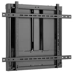
Interactive
Flat-Panel
Wall Mount
Models: DWM5070HD, DWM7090HD
1111 W. 35th Street, Chicago, IL 60609 USA • tripplite.com/support
Copyright © 2022 Tripp Lite. All rights reserved.
Este manual está disponible en español en la página de Tripp Lite: tripplite.com
Ce manuel est disponible en français sur le site Web de Tripp Lite : tripplite.com
Русскоязычная версия настоящего руководства представлена на веб-сайте компании
Tripp Lite по адресу: tripplite.com
Dieses Handbuch ist in deutscher Sprache auf der Tripp Lite-Website verfügbar: tripplite.com
WARRANTY REGISTRATION
Register your product today and be
automatically entered to win an ISOBAR
®
surge protector in our monthly drawing!
tripplite.com/warranty
CAUTION: DO NOT EXCEED MAXIMUM LISTED WEIGHT CAPACITY. SERIOUS INJURY OR
PROPERTY DAMAGE MAY OCCUR!
200x200 / 300x200 / 300x300
400x200 / 400x300 / 400x400
600x400 / 700x400 / 800x400
800x500 / 800x600
70"
MAX
90"
MAX
88-132 lb.88-132 lb.
(40-60 kg)(40-60 kg)
RATEDRATED
132-198 lb.132-198 lb.
(60-90 kg)(60-90 kg)
RATEDRATED
DWM5070HD
DWM5070HDDWM5070HD
DWM7090HD
DWM7090HDDWM7090HD

2
Safety Instructions
Warranty and Product Registration
Note: Read the entire instruction manual before you start assembly and installation.
WARNING
• Do not begin the installation until you have read and understood the instructions and warnings contained in this
manual. If you have any questions regarding any of the instructions or warnings, please visit tripplite.com/support.
• This mounting bracket was designed to be installed and utilized ONLY as specied in this manual. Improper
installation of this product may cause damage or serious injury.
• This product should only be installed by someone of good mechanical ability, with basic building experience and a
full understanding of this manual.
• Make sure that the supporting surface will safely support the combined load of the equipment and all attached
hardware and components.
• If mounting to wood wall studs, make sure that mounting screws are anchored into the center of the studs. The use
of a stud nder is highly recommended.
• Always use an assistant or mechanical lifting equipment to safely lift and position equipment.
• Tighten screws rmly, but do not over tighten. Over tightening can damage the items, greatly reducing their holding
power.
• This product is intended for indoor use only. Using this product outdoors could lead to product failure and personal
injury.
5-Year Limited Warranty
Seller warrants this product, if used in accordance with all applicable instructions, to be free from original defects in material and workmanship for a
period of 5 years from the date of initial purchase. If the product should prove defective in material or workmanship within that period, Seller will repair or
replace the product, at its sole discretion.
THIS WARRANTY DOES NOT APPLY TO NORMAL WEAR OR TO DAMAGE RESULTING FROM ACCIDENT, MISUSE, ABUSE OR NEGLECT.
SELLER MAKES NO EXPRESS WARRANTIES OTHER THAN THE WARRANTY EXPRESSLY SET FORTH HEREIN. EXCEPT TO THE EXTENT
PROHIBITED BY APPLICABLE LAW, ALL IMPLIED WARRANTIES, INCLUDING ALL WARRANTIES OF MERCHANTABILITY OR FITNESS, ARE
LIMITED IN DURATION TO THE WARRANTY PERIOD SET FORTH ABOVE; AND THIS WARRANTY EXPRESSLY EXCLUDES ALL INCIDENTAL AND
CONSEQUENTIAL DAMAGES. (Some states do not allow limitations on how long an implied warranty lasts, and some states do not allow the exclusion
or limitation of incidental or consequential damages, so the above limitations or exclusions may not apply to you. This warranty gives you specic legal
rights, and you may have other rights which vary from jurisdiction to jurisdiction.)
WARNING: The individual user should take care to determine prior to use whether this device is suitable, adequate or safe for the use intended. Since
individual applications are subject to great variation, the manufacturer makes no representation or warranty as to the suitability or tness of these
devices for any specic application.
PRODUCT REGISTRATION
Visit tripplite.com/warranty today to register your new Tripp Lite product. You’ll be automatically entered into a drawing for a chance to win a FREE
Tripp Lite product!*
* No purchase necessary. Void where prohibited. Some restrictions apply. See website for details.
Tripp Lite has a policy of continuous improvement. Specications are subject to change without notice. Photos and illustrations may dier slightly from
actual products.
3
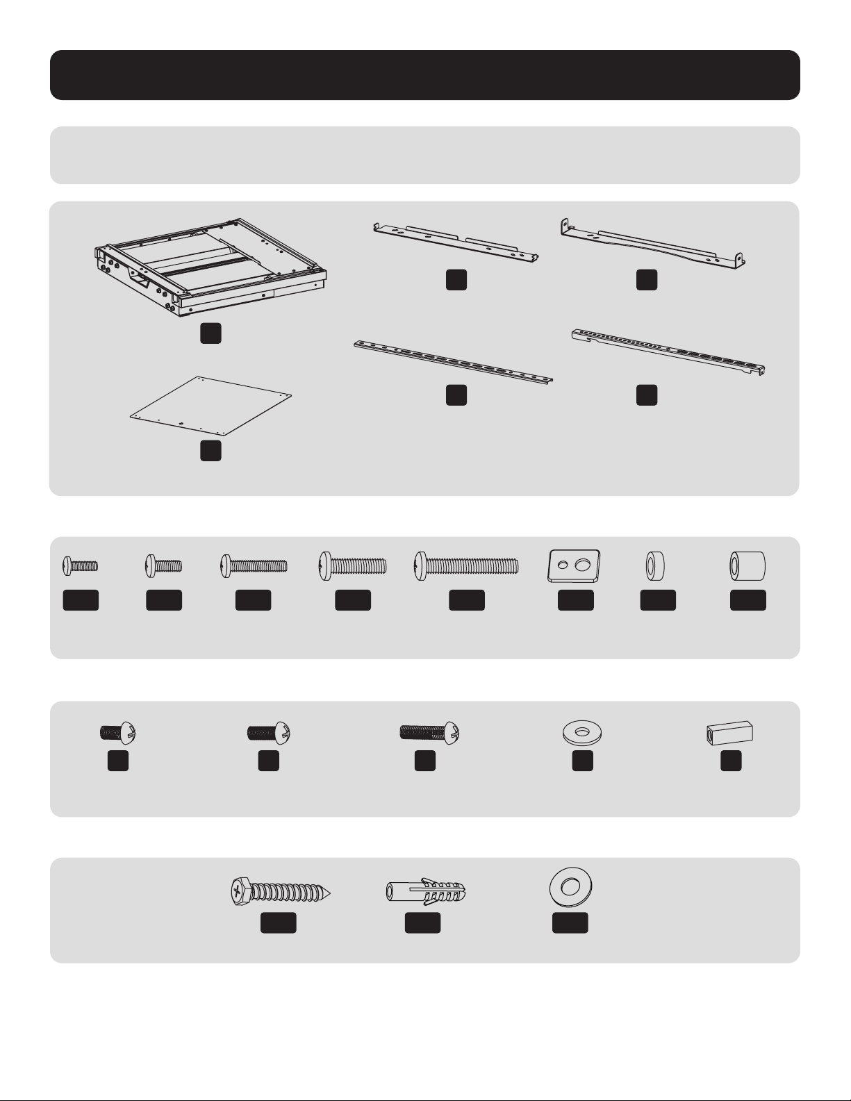
Component Checklist
IMPORTANT: Ensure you have received all parts according to the component checklist prior to installing. If any
parts are missing or faulty, visit tripplite.com/support for service.
Package M
Package P
Package W
A
(x1)
B
(x1)
D
(x2)
F
(x1)
G
M6x12
(x4)
H
M6x16
(x2)
I
M6x25
(x2)
J
(x4)
K
(x1)
C
(x1)
E
(x2)
M-A
M5x14
(x4)
W-A
(x6)
W-B
(x6)
W-C
(x6)
M-B
M6x14
(x4)
M-C
M6x30
(x4)
M-D
M8x30
(x4)
M-E
M8x50
(x4)
M-F
Washer
(x4)
M-G
Small Spacer
(x8)
M-H
Large Spacer
(x8)
4
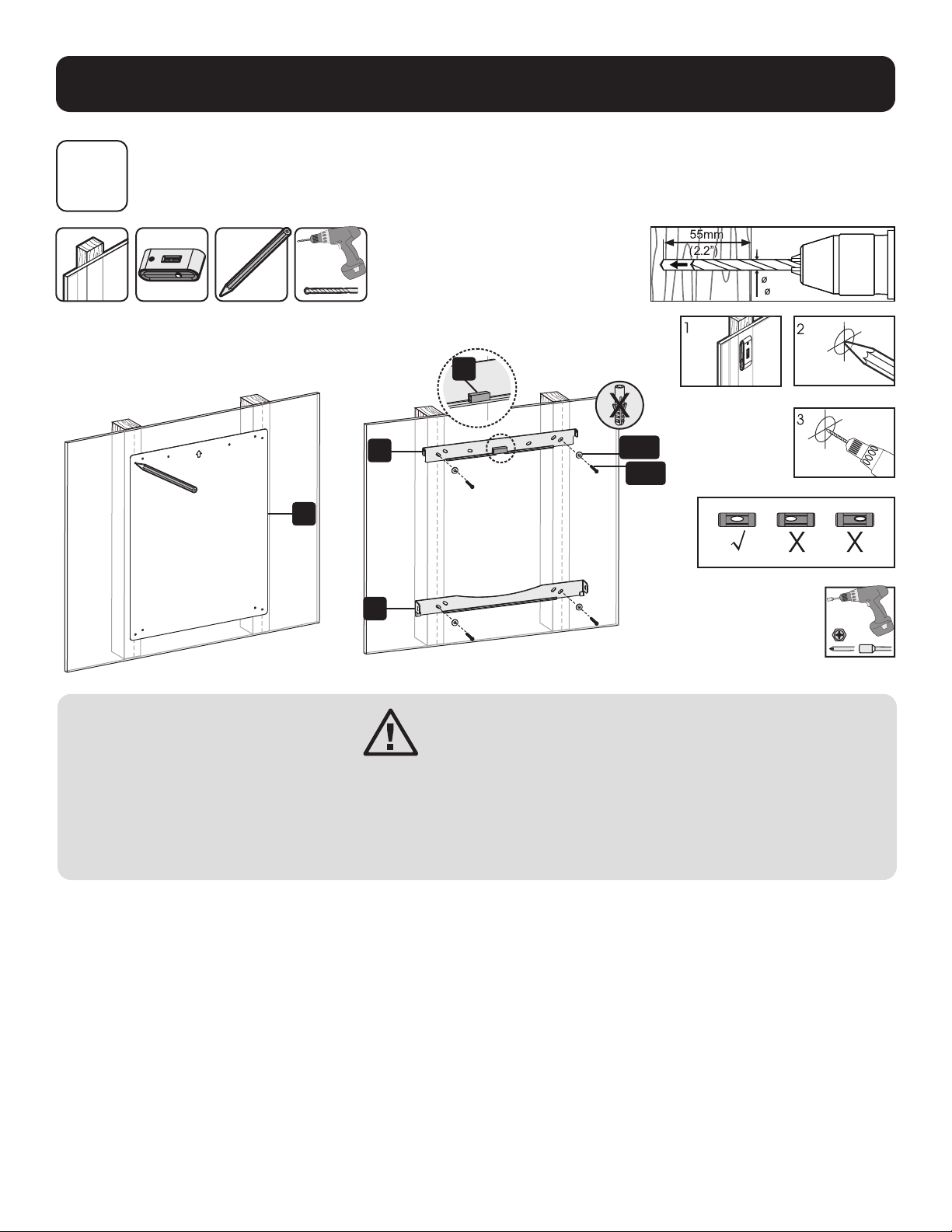
Assembly
1
Attach Mount Assembly Brackets to Wall
1a. Mount on Wood Stud Wall
55mm55mm
(2.2")(2.2")
4.5mm4.5mm
( 3/16")( 3/16")
Find and mark the
exact location of
mounting holes
Drill pilot holes
Screw the brackets
onto the wall
W-C
W-A
F
C
B
K
WARNING
• Make sure that mounting screws are anchored into the center of the studs. Use of a stud nder is highly
recommended.
• Installers are responsible to provide hardware for other types of mounting situations.
• Installers must verify that the supporting surface will safely support the combined load of the equipment
and all attached hardware and components.
5
Assembly
1
Attach Mount Assembly Brackets to Wall
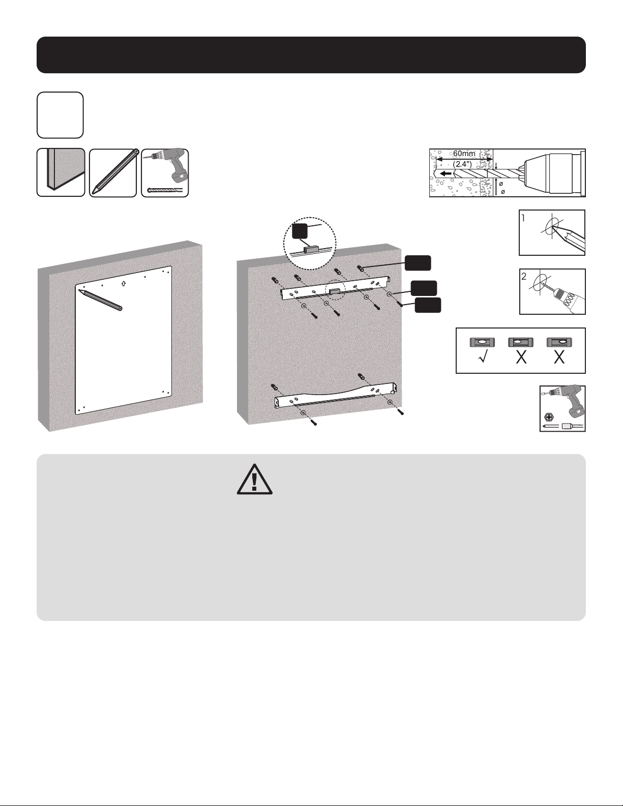
1b. Mount on Solid Brick and Concrete Block
WARNING
• When installing wall mounts onto a concrete masonry unit (also known as a CMU or “cinder block”), verify
that the actual concrete thickness is at least 35 mm (1-3/8") in order to hold the concrete anchors. DO
NOT DRILL INTO MORTAR JOINTS! Be sure to mount the assembled wall-mount plate with the included
concrete anchors, D6 washers and anchor bolts onto solid sections of the blocks. The solid sections can
generally be found 25 mm (1") toward the middle of the block from either end. An electric drill on a slow
setting is suggested to drill the hole rather than a hammer drill so as to avoid breaking out the back of the
hole when entering a hollow section.
• Installers must verify that the supporting surface will safely support the combined load of the equipment
and all attached hardware and components.
60mm60mm
(2.4")(2.4")
10mm10mm
( 3/8")( 3/8")
Find and mark the
exact location of
mounting holes
Drill pilot holes
Screw the brackets
onto the wall
K
W-C
W-B
W-A
6
Assembly
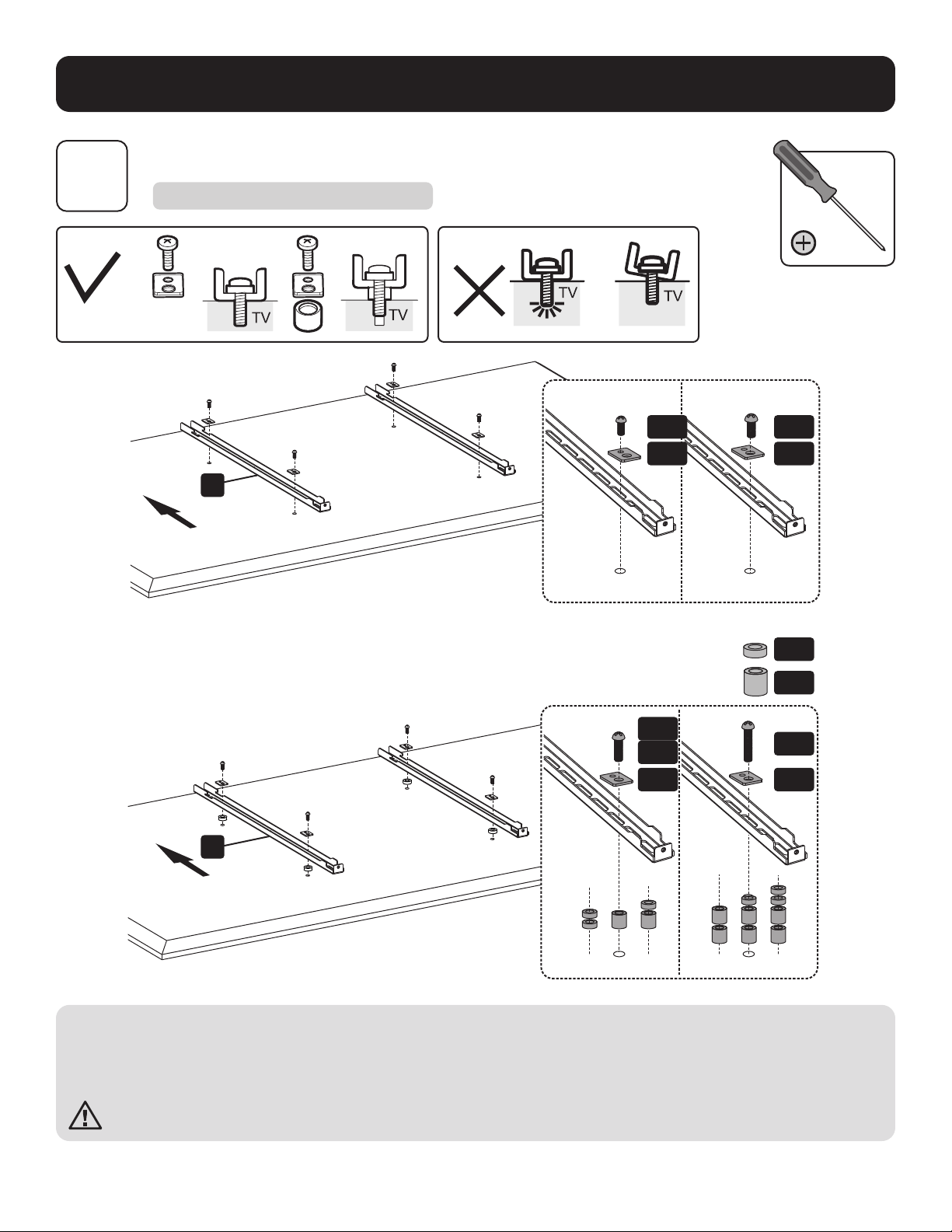
2
Install Adapter Brackets
2a. For Flat-Back Screens
E
M-B
M-F
M-F
M-E
M-G
M-H
M-A
M-C
M-D
M-F
M-F
Note: Choose appropriate screws, washers and spacers (if necessary) according to the type of screen.
• Position the adapter brackets as close as possible to the center of the display.
• Firmly secure the adapter brackets onto the display using the screws and any other necessary hardware components included
with the unit.
Do not over-tighten screws.
E
7
M-B
M-F
M-F
M-E
M-G
M-H
M-A
M-C
M-D
M-F
M-F
D
D
Assembly
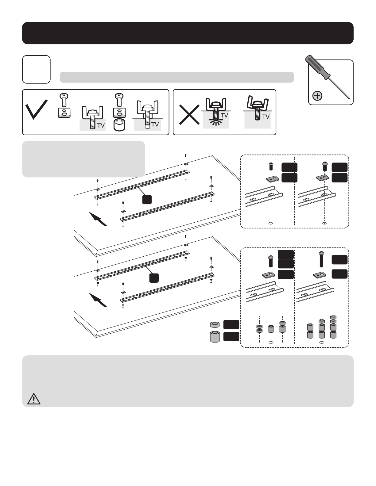
2
Install Adapter Brackets
2b-1. For Recessed Back Screen or to Access A/V Inputs
Note: The horizontal brackets are used
ONLY with interactive smart whiteboards that
have 600x400/700x400/800x400/800x500/
800x600 VESA patterns.
Note: Choose appropriate screws, washers and spacers (if necessary) according to the type of screen.
• Position the adapter brackets as close as possible to the center of the display.
• Firmly secure the adapter brackets onto the display using the screws and any other necessary hardware components included
with the unit.
Do not over-tighten screws.
8
Assembly
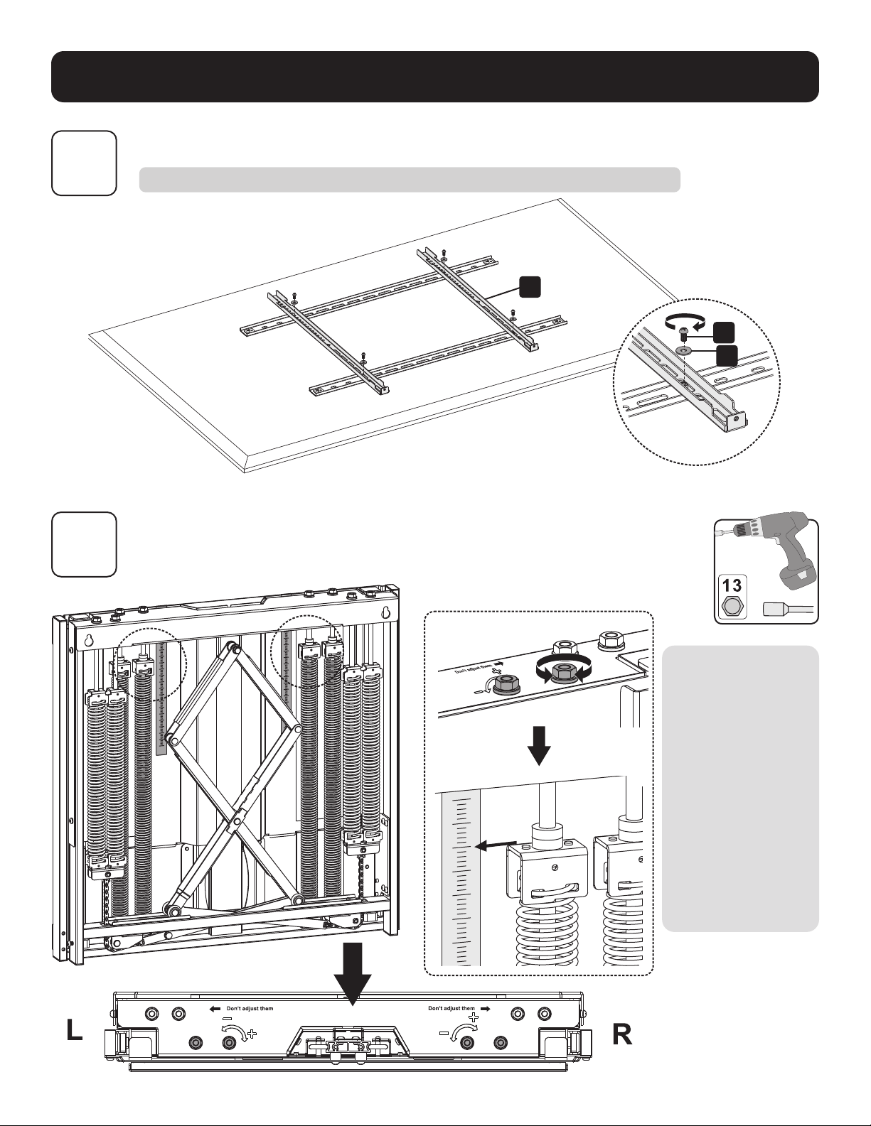
3
Adjust Balance Bolts
The mount arrives
with a default balance
setting. Adjust to
the number found
on the scale that
matches the weight
of the whiteboard. To
properly balance the
unit, use a drill with
a nut-driver to adjust
the four balance bolts
(two located on each
side, left and right).
Alternate between
each side until it has
achieved a perfect
balance.
E
G
J
2
Install Adapter Brackets
2b-2 For Recessed Back Screen or to Access A/V Inputs
9
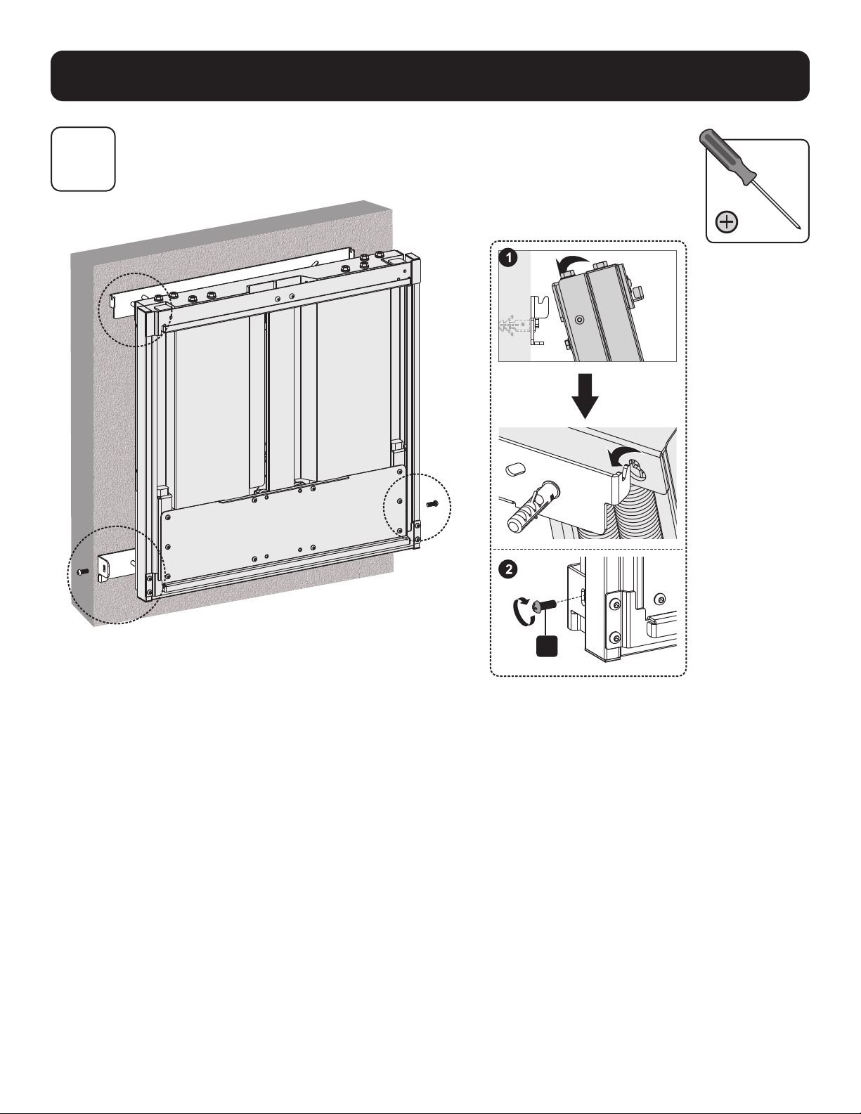
Assembly
4
Hang Mount Assembly
H
10
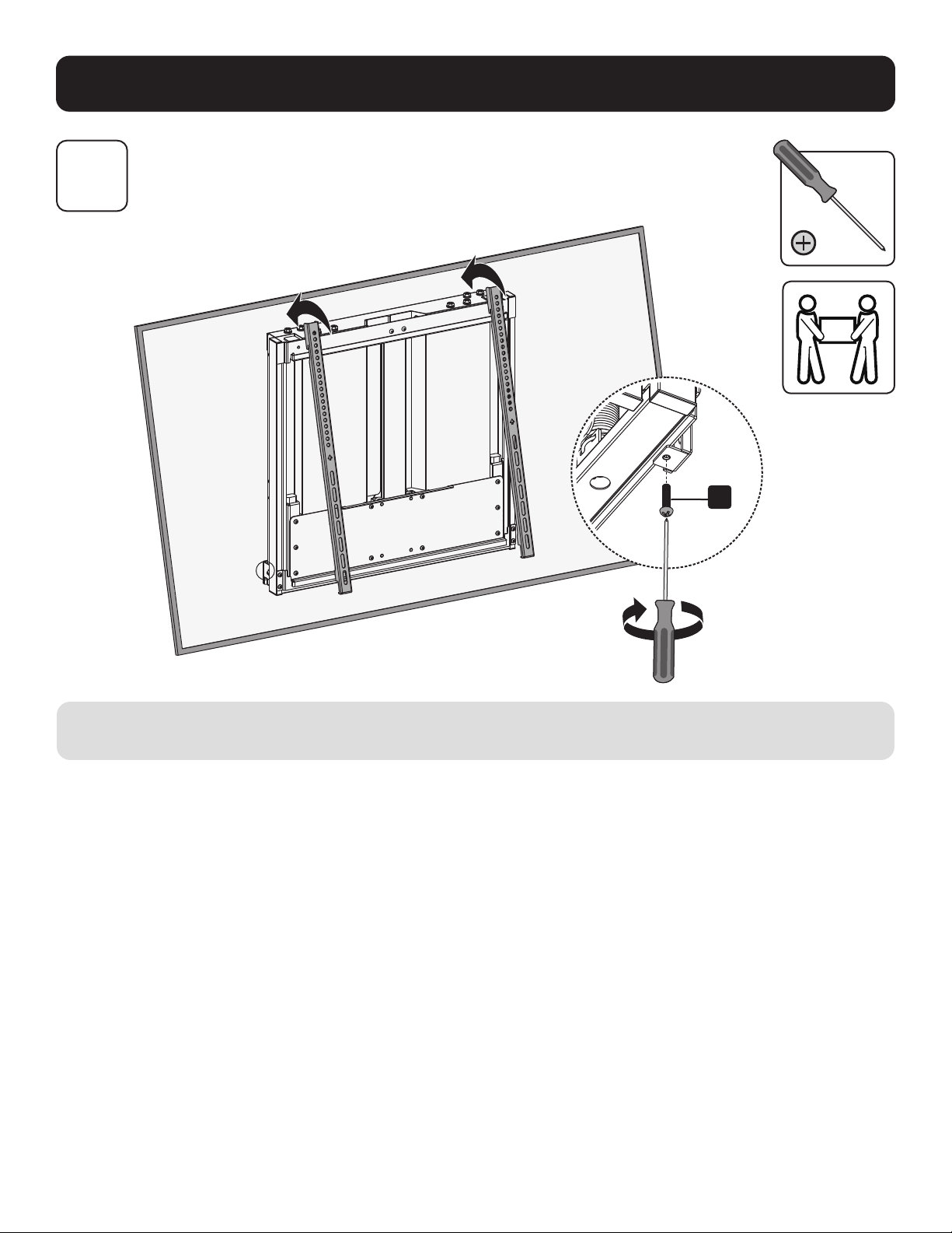
Assembly
5
Hang Display On Mount Assembly
Using an assistant or mechanical lifting equipment, hook the display with attached adapter brackets over the top of the mounted
wall-plate. Tighten the two bolts on the bottom of the adapter brackets to secure the unit.
I
11
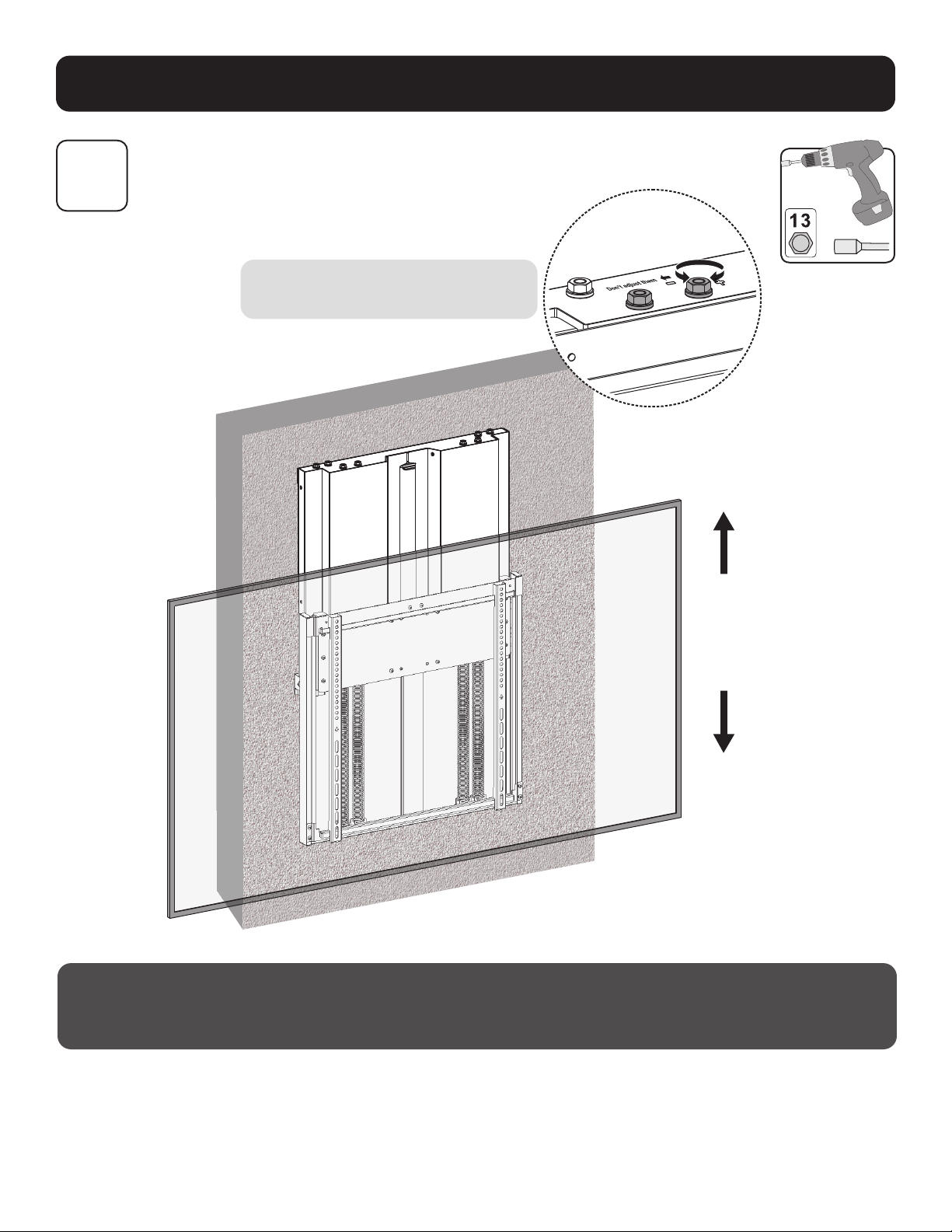
Assembly
6
Adjustment
To ensure a perfect balance, use a drill with
a nut-driver to make ne adjustments.
Maintenance
• Check that the bracket is secure and safe to use at regular intervals (at least every three months).
• Please visit tripplite.com/support if you have any questions.
15.75 in.
(400 mm)

12
1111 W. 35th Street, Chicago, IL 60609 USA • tripplite.com/support
22-03-017 933D81_RevB