1
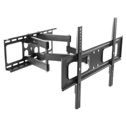
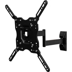
Full-Motion Flat-Screen
Wall Mount
Model: DWM2355S
1111 W. 35th Street, Chicago, IL 60609 USA • tripplite.com/support
Copyright © 2020 Tripp Lite. All rights reserved.
WARNING! Always use an assistant or mechanical lifting equipment to safely lift and position equipment.
75x75/100x100
200x100/200x200
300x300/400x200
400x300/400x400
55"
MAX
11-50.6 lbs11-50.6 lbs
(5-23 kg)(5-23 kg)
RatedRated
WARRANTY REGISTRATION
Register your product today and be automatically entered to win an ISOBAR
®
surge protector in our monthly drawing!
tripplite.com/warranty
Español 13 • Français 25 • Русский 37 • Deutsch 49
Owner’s Manual

2
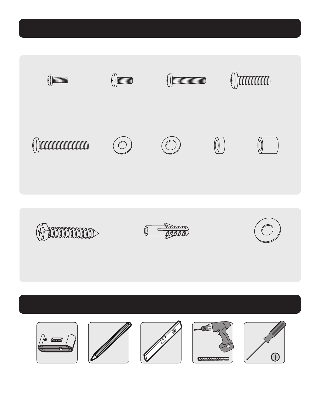
Parts List
Important Safety Instructions
CAUTION
• Read the entire instruction manual before you start assembly and installation. If you have questions about any of
the instructions or warnings, contact Tripp Lite Support.
• Use with products heavier than the rated weights indicated may result in instability, causing possible injury.
• Mounts must be attached as specified in these instructions. Improper installation may result in damage or serious
personal injury.
• Safety gear and proper tools must be used. This product should only be installed by professionals.
• This product is designed to be installed on wood stud walls, solid concrete walls or brick walls.
• Ensure the supporting surface will safely support the combined weight of the equipment and all attached hardware
and components.
• Use the mounting screws provided and DO NOT OVERTIGHTEN the mounting screws.
• This product contains small items that could be a choking hazard if swallowed. Keep these items away from children.
• This product is intended for indoor use only. Using this product outdoors could lead to product failure and
personal injury.
• Check that the bracket is secure and safe to use at regular intervals (at least every three months)
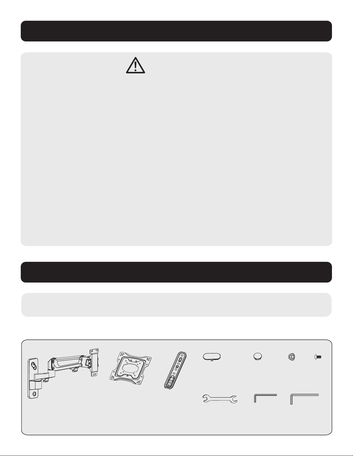
IMPORTANT: Before beginning installation, be sure you have received all the parts listed below.
If any parts are missing or faulty, contact Tripp Lite for replacements.
A
Wall Plate/
Articulating Arm (x1)
Components
B
VESA Plate (x1)
C
VESA Adapter
Bracket (x4)
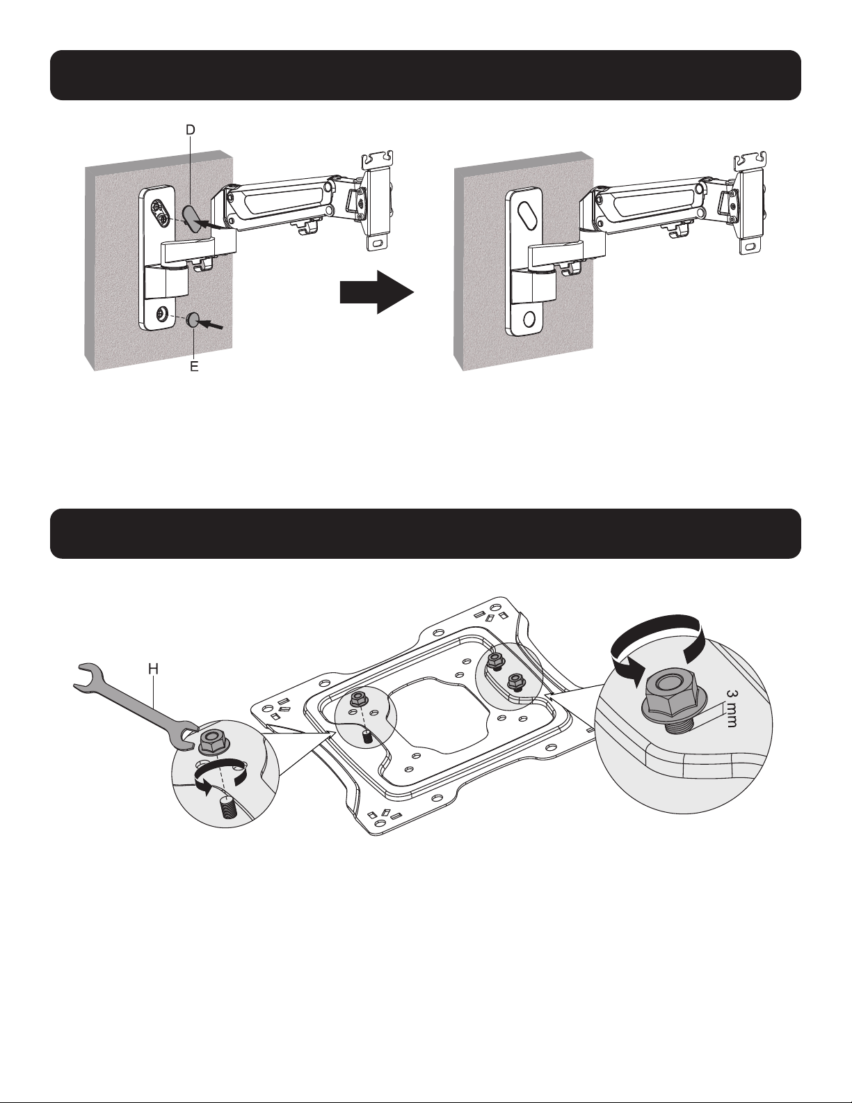
D
Wall Plate
End Cap (x1)
E
Wall Plate
End Cap (x1)
F
Nut
(x4)
G
Bolt
(x4)
H
Wrench
(x1)
I
4 mm Hex
Key (x1)
J
6 mm Hex
Key (x1)
3
Parts List
Stud finder
(for installation
on wood stud wall)
Pencil Level Drill with
appropriate bits
(for installation type)
Screwdriver
W-B
Concrete Anchor (x3)
W-A
Anchor Bolt (x3)
W-C
Washer (x3)
Package M
Package W
M-A
M5x14 (x4)
M-E
M8x50 (x4)
M-B
M6x14 (x4)
M-F
D5 Washer (x4)
M-C
M6x30 (x4)
M-H
Smaller Spacer (x8)
M-D
M8x30 (x4)
M-I
Large Spacer (x8)
M-G
D8 Washer (x4)
Required for Installation

4
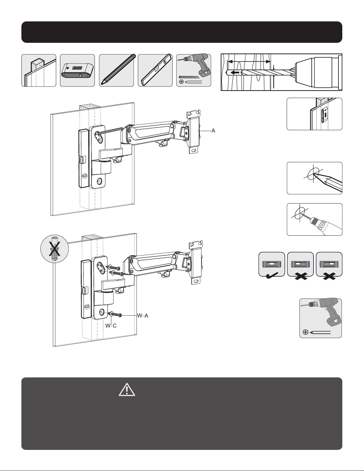
1a. Mount on Wood Stud Wall
1
2
3
Find and mark the
exact location of
mounting holes
Screw mount
into wall
Drill pilot holes
WARNING
• Make sure the mounting screws are anchored into the center of the studs. Use of a stud finder is highly
recommended.
• The installer is responsible to provide hardware for other types of mounting situations.
• The installer must verify the supporting surface will safely support the combined load of the equipment
and all attached hardware and components.
Ensure holes are level
60mm
2.4”()
55mm
(2.2")
Ø 4.5mm
(Ø 3/16")
1a
1a

5
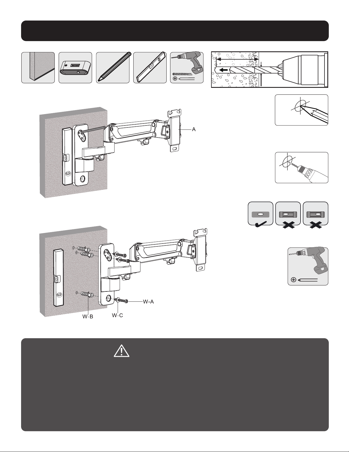
WARNING
• When installing wall mount onto a concrete masonry unit (also known as a CMU or cinder block), verify
the actual concrete thickness is at least 1-3/8” (35 mm) in order to hold the concrete anchors. DO NOT
DRILL INTO MORTAR JOINTS! Be sure to mount the assembled wall-mount plate with the included concrete
anchors, D6 washers and anchor bolts onto solid sections of the blocks. The solid sections can generally
be found 1” (25 mm) toward the middle of the block from either end. An electric drill on a slow setting is
recommended to drill the hole rather than a hammer drill to avoid breaking out the back of the hole when
entering a hollow section.
• The installer must verify the supporting surface will safely support the combined load of the equipment and
all attached hardware and components.
1b. Mount on Solid Brick or Concrete Block
1
2
Find and mark the
exact location of
mounting holes
Screw mount
into wall
Drill pilot holes
Ensure holes are level
Ensure holes are level
65mm
2.6"()
60mm
(2.4")
Ø 10mm
(Ø 3/8")
1
1b
1b

6
2. Install Articulating Arm
3. Prepare VESA Plate
2
3

7
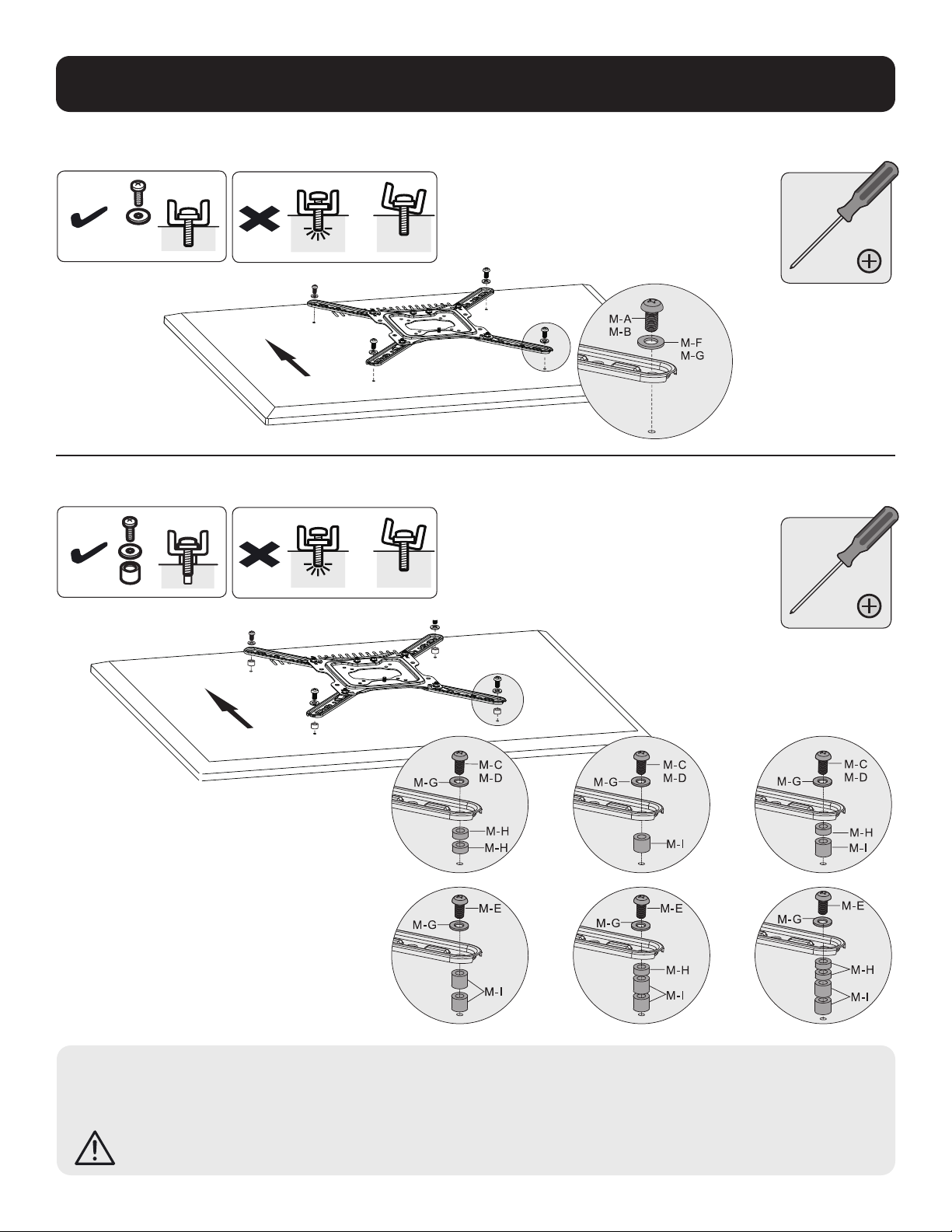
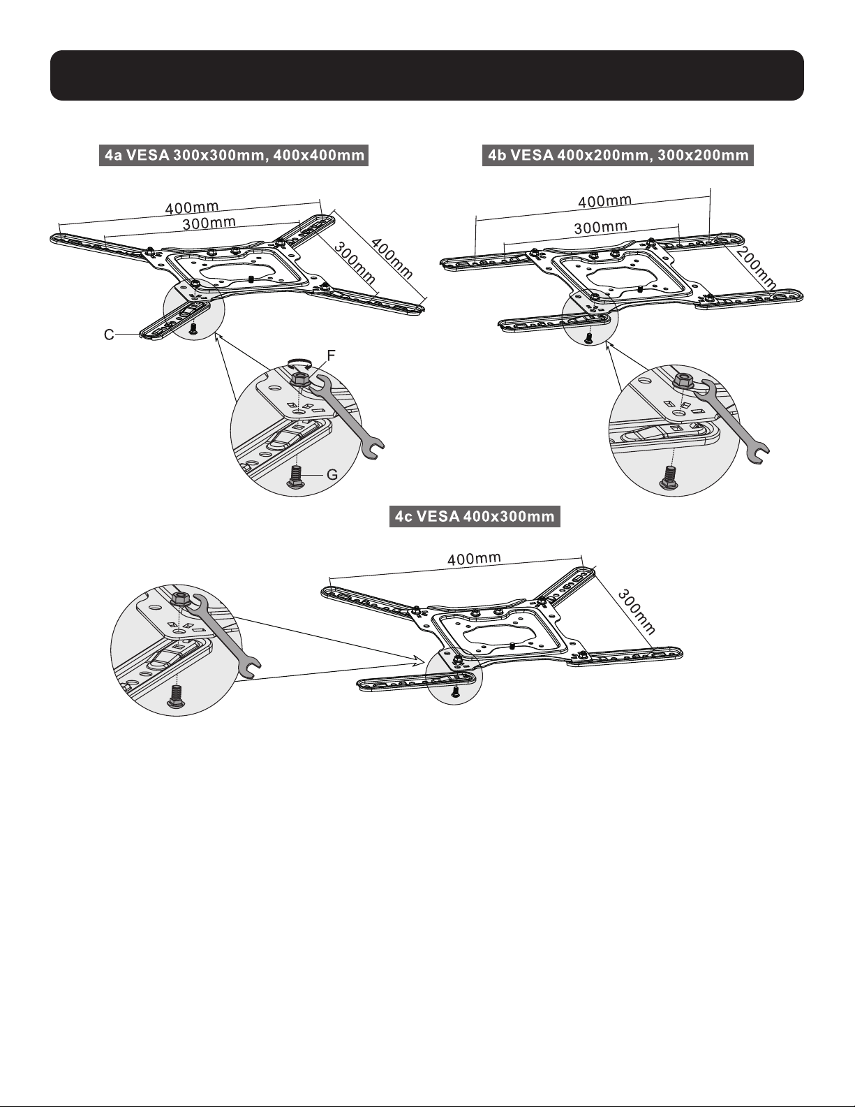
4. Attach VESA Adapter Brackets
4
8
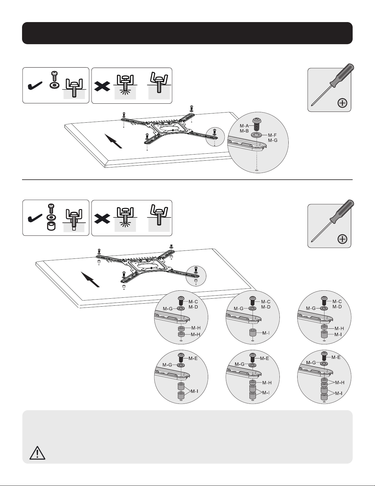
5. Mount Brackets to Display
TV
TV
TV
TV
TV
TV
Note: Choose appropriate screws, washers and spacers (if necessary) according to the type of screen.
• Position the adapter brackets as close as possible to the center of the display.
• Firmly secure the adapter brackets onto the display using the screws and any other necessary hardware components included with the unit.
DO NOT OVERTIGHTEN SCREWS!
5a
5b
5a
5b

9
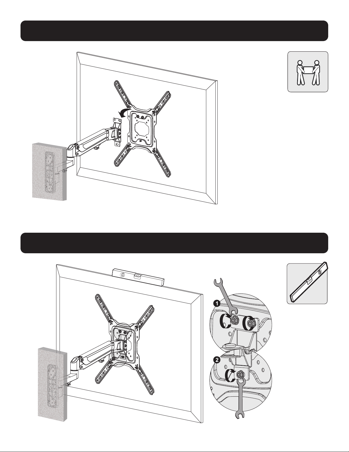
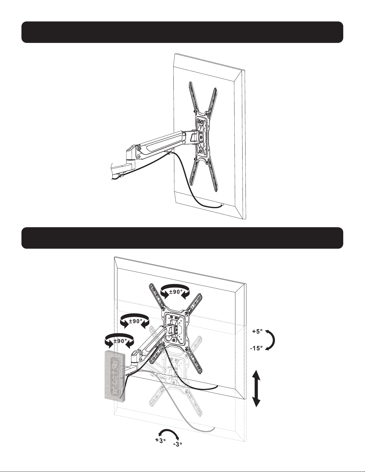
6. Hang Flat Screen onto Articulating Arm
7. Level and Tighten Screen
7

10
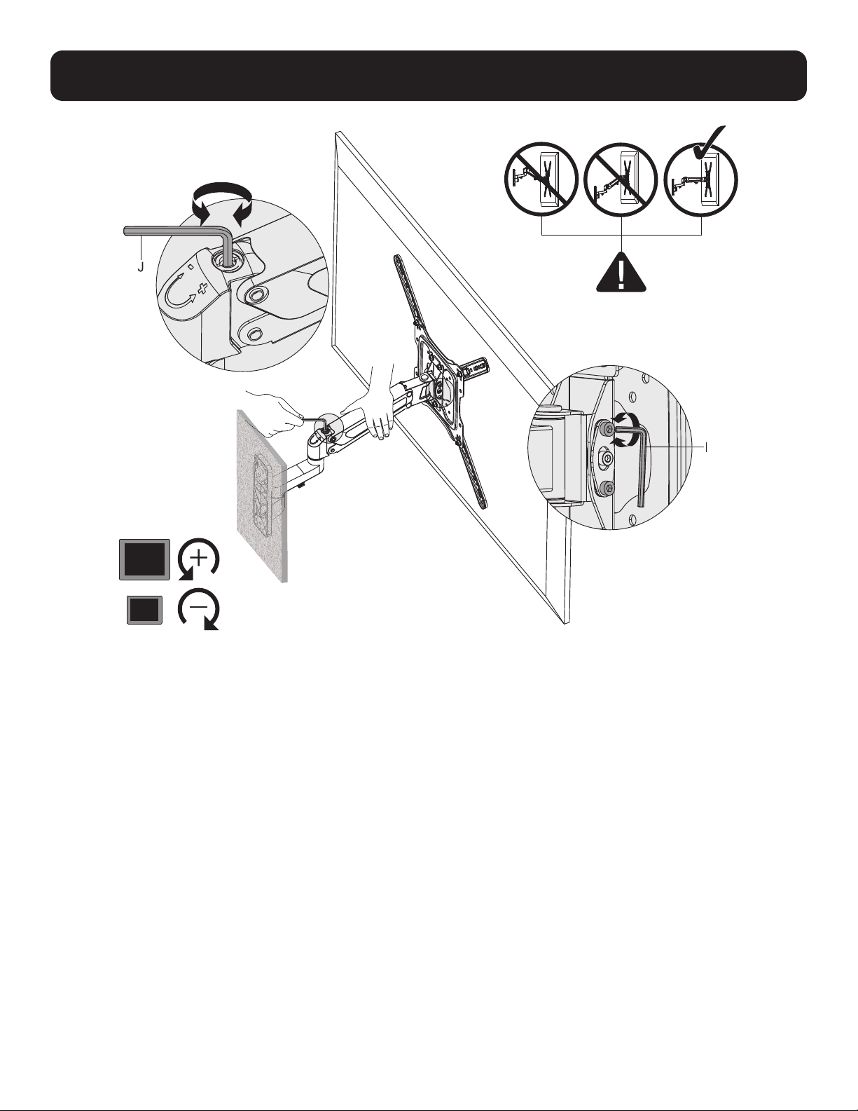
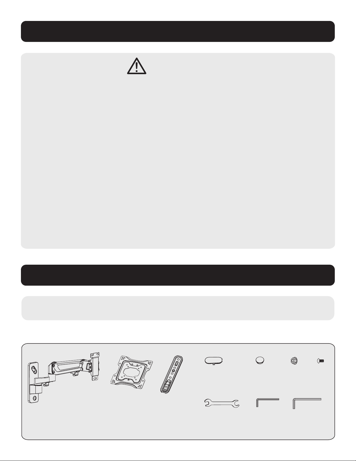
8. Adjust Articulating Arm
8

11
9. Route Cables
9
10
10. Adjust Viewing Angle

12
1111 W. 35th Street, Chicago, IL 60609 USA • tripplite.com/support
20-06-293 93-3CC2_RevA
Warranty and Product Registration
5-Year Limited Warranty
Seller warrants this product, if used in accordance with all applicable instructions, to be free from original defects in material
and workmanship for a period of 5 years from the date of initial purchase. If the product should prove defective in material or
workmanship within that period, Seller will repair or replace the product, at its sole discretion.
THIS WARRANTY DOES NOT APPLY TO NORMAL WEAR OR TO DAMAGE RESULTING FROM ACCIDENT, MISUSE, ABUSE
OR NEGLECT. SELLER MAKES NO EXPRESS WARRANTIES OTHER THAN THE WARRANTY EXPRESSLY SET FORTH HEREIN.
EXCEPT TO THE EXTENT PROHIBITED BY APPLICABLE LAW, ALL IMPLIED WARRANTIES, INCLUDING ALL WARRANTIES OF
MERCHANTABILITY OR FITNESS, ARE LIMITED IN DURATION TO THE WARRANTY PERIOD SET FORTH ABOVE; AND THIS
WARRANTY EXPRESSLY EXCLUDES ALL INCIDENTAL AND CONSEQUENTIAL DAMAGES. (Some states do not allow limitations
on how long an implied warranty lasts, and some states do not allow the exclusion or limitation of incidental or consequential
damages, so the above limitations or exclusions may not apply to you. This warranty gives you specific legal rights, and you
may have other rights which vary from jurisdiction to jurisdiction.)
WARNING: The individual user should take care to determine prior to use whether this device is suitable, adequate or safe for
the use intended. Since individual applications are subject to great variation, the manufacturer makes no representation or
warranty as to the suitability or fitness of these devices for any specific application.
PRODUCT REGISTRATION
Visit tripplite.com/warranty today to register your new Tripp Lite product. You’ll be automatically entered into a drawing for a
chance to win a FREE Tripp Lite product!*
* No purchase necessary. Void where prohibited. Some restrictions apply. See website for details.
Tripp Lite has a policy of continuous improvement. Specifications are subject to change without notice. Images may differ slightly from actual products.

13
MÁS DE
AÑOS
Soporte de Pared con Movimiento
Completo para Pantalla Plana
Modelo: DWM2355S
1111 W. 35th Street, Chicago, IL 60609, EE UU • tripplite.com/support
Copyright © 2020 Tripp Lite. Todos los derechos reservados.
¡ADVERTENCIA! Utilice siempre un ayudante o equipo de elevación mecánico para levantar y colocar
el equipo con seguridad.
75x75 / 100x100
200x100 / 200x200
300x300 / 400x200
400x300 / 400x400
55"
MÁXIMO
[11.0 lb ~ 50.6 lb][11.0 lb ~ 50.6 lb]
5 Kg ~ 23 kg5 Kg ~ 23 kg
ClasificadoClasificado
English 1 • Français 25 • Русский 37 • Deutsch 49
Manual del Propietario

14
Lista de Partes
Instrucciones de Seguridad Importantes
PRECAUCIÓN
• Lea todo el manual de instrucciones antes de iniciar el ensamble y la instalación. Si tiene preguntas sobre cualquiera de las
instrucciones o advertencias, póngase en contacto con el Soporte de Tripp Lite.
• El uso con productos más pesados que los pesos nominales especificados puede resultar en inestabilidad y causar posibles
lesiones.
• Los soportes deben instalarse como se especifica en estas instrucciones. La instalación incorrecta puede causar daños o
lesiones personales graves.
• Se deben usar equipos de seguridad y herramientas adecuadas. Este producto debe ser instalado únicamente por
profesionales.
• Este producto está diseñado para ser instalado en paredes con travesaños de madera, paredes de concreto sólido o paredes
de ladrillo.
• Asegúrese de que la superficie de apoyo soporte con seguridad el peso combinado del equipo y de todos los accesorios y
componentes instalados.
• Use los tornillos de instalación suministrados y NO APRIETE EN EXCESO los tornillos de instalación.
• Este producto contiene pequeñas piezas que pueden ser un riesgo de asfixia si se ingieren. Mantenga estas piezas fuera del
alcance de los niños.
• Este producto está diseñado para usarse solo en interiores. Usar este producto en exteriores podría derivar en fallas del
producto y lesiones personales.
• Compruebe a intervalos regulares (al menos trimestralmente) que el soporte esté firme y que su uso sea seguro.
IMPORTANTE: Antes de comenzar la instalación, asegúrese de haber recibido todas las partes que se
enumeran a continuación. Si faltara cualquier parte o estuviese dañada, póngase en contacto con Tripp Lite para
solicitar reemplazos.
A
Placa de Pared /
Brazo Articulado (x1)
Componentes
B
Placa
VESA (x1)
C
Soporte de
Adaptador VESA
(x4)
D
Tapa de Extremo
de Placa de
Pared (x1)
E
Tapa de
Extremo de
Placa de Pared (x1)
F
Tuerca
(x4)
G
Tornillo
(x4)
H
Llave (x1)
I
Llave
Hexagonal de
4 mm (x1)
J
Llave
Hexagonal
de 6 mm (x1)

15
Lista de Partes
Localizador de
travesaños
Lápiz Nivel Perfore con
las brocas
adecuadas
Desatornillador
W-B
Taquete (x3)
W-A
Tornillo de Anclaje
(x3)
W-C
Arandela (x3)
Paquete M
Paquete W
M-A
M5x14 (x4)
M-E
M8x50 (x4)
M-B
M6x14 (x4)
M-F
Arandela D5
(x4)
M-C
M6x30 (x4)
M-H
Espaciador Pequeño
(x8)
M-D
M8x30 (x4)
M-I
Espaciador
Grande (x8)
M-G
Arandela D8
(x4)
Requerido para Instalación
(para el tipo de instalación)
(Para instalación en
pared con travesaños
de madera)

16
1a. Instalación en Pared con Entramado de Madera
1
2
3
Encuentre y marque
la posición exacta
de los orificios de
instalación
Atornille el
soporte en la
pared
Perfore los
orificios piloto
ADVERTENCIA
• Cerciórese que los tornillos de instalación estén anclados en el centro de los travesaños. Es muy recomendable
usar un detector de vigas.
• El instalador es responsable de proporcionar los accesorios para otros tipos de soluciones de instalación.
• El instalador debe verificar que la superficie de apoyo soporte con seguridad la carga combinada del equipo
y todo el hardware y componentes instalados.
Asegúrese de que los
orificios estén nivelados
60mm
2.4”()
55 mm
[2.2"]
Ø 4.5 mm
[Ø 3/16"]
1a
1a

17
ADVERTENCIA
• Al instalar un soporte de pared en una unidad de mampostería de concreto (conocida también como CMU
o bloques de concreto), verifique que el espesor real del concreto sea de al menos 35 mm [1 3/8”] a fin de
que pueda sujetar los taquetes para concreto. ¡NO TALADRE EN LAS UNIONES DE ARGAMASA! Asegúrese
de instalar la placa de pared ensamblada con los taquetes para concreto, arandelas D6 y tornillos de anclaje
incluidos en las secciones sólidas de los bloques. Las secciones sólidas pueden encontrarse generalmente a
25 mm [1”] hacia el centro del bloque desde cualquier extremo. Se recomienda utilizar un taladro eléctrico
a baja velocidad para barrenar el orificio en vez de un rotomartillo para evitar rotura de la parte posterior del
orificio al entrar en una sección hueca.
• El instalador debe verificar que la superficie de apoyo soporte con seguridad la carga combinada de todo el
hardware y componentes instalados.
1b.
Instalación sobre Ladrillos Sólidos o Bloques de Concreto
1
2
Encuentre y marque
la posición exacta
de los orificios de
instalación
Atornille el
soporte en la
pared
Perfore los
orificios piloto
Asegúrese de que los
orificios estén nivelados
65mm
2.6"()
60 mm
[2.4"]
Ø 10 mm
[Ø 3/8"]
1
1b
1b

18
2. Instale el Brazo Articulado
3. Prepare la Placa VESA
2
3

19
4. Instale los Soportes del Adaptador VESA
4

20
5. Instale los Soportes a la Pantalla
TV
TV
TV
TV
TV
TV
Note: Elija los tornillos, arandelas y espaciadores (si fueran necesarios) apropiados de acuerdo al tipo de pantalla.
• Coloque los soportes adaptadores tan cerca como sea posible al centro de la pantalla.
• Asegure firmemente los soportes adaptadores en la pantalla usando los tornillos y cualquier otro componente necesario incluido en la unidad.
¡NO APRIETE LOS TORNILLOS EN EXCESO!
5a
5b
5a
5b
21
6. Cuelgue la Pantalla Plana en el Brazo Articulado
7. Nivele y Apriete la Pantalla
7
22
8. Ajuste del Brazo Articulado
8

23
9. Enrute los Cables
9
10
10. Ajuste el Ángulo de Visualización

24
MÁS DE
AÑOS
1111 W. 35th Street, Chicago, IL 60609, EE UU • tripplite.com/support
20-06-293 93-3CC2_RevA
Garantía
Garantía Limitada por 5 Años
El vendedor garantiza este producto, si se usa de acuerdo con todas las instrucciones aplicables, de que está libre de defectos
en cuanto a materiales y mano de obra por un período de 5 años a partir de la fecha de compra inicial. Si el producto resulta
defectuoso en cuanto a materiales o mano de obra dentro de ese período, el vendedor reparará o reemplazará el producto a
su entera discreción.
ESTA GARANTÍA NO SE APLICA AL DESGASTE NORMAL O A LOS DAÑOS QUE RESULTEN DE ACCIDENTES, USO INCORRECTO,
USO INDEBIDO O NEGLIGENCIA. EL VENDEDOR NO OTORGA GARANTÍAS EXPRESAS DISTINTAS A LA ESTIPULADA EN EL
PRESENTE. SALVO EN LA MEDIDA EN QUE LO PROHÍBAN LAS LEYES APLICABLES, TODAS LAS GARANTÍAS IMPLÍCITAS,
INCLUIDAS TODAS LAS GARANTÍAS DE COMERCIALIZACIÓN O IDONEIDAD, ESTÁN LIMITADAS EN CUANTO A DURACIÓN
AL PERÍODO DE GARANTÍA ESTABLECIDO; ASIMISMO, ESTA GARANTÍA EXCLUYE EXPRESAMENTE TODOS LOS DAÑOS
INCIDENTALES E INDIRECTOS. (Algunos estados no permiten limitaciones en cuanto a la duración de una garantía y algunos
estados no permiten la exclusión o limitación de daños incidentales o indirectos, de modo que es posible que las limitaciones
anteriores no se apliquen a usted. Esta garantía le otorga derechos legales específicos y es posible que usted goce de otros
derechos que pueden variar de una jurisdicción a otra).
ADVERTENCIA: antes de usarlo, cada usuario debe tener cuidado al determinar si este dispositivo es adecuado o seguro para
el uso previsto. Ya que las aplicaciones individuales están sujetas a gran variación, el fabricante no garantiza la adecuación de
estos dispositivos para alguna aplicación específica.

25
Support mural à mouvement
complet pour écran plat
Modèle : DWM2355S
1111 W. 35th Street, Chicago, IL 60609 USA tripplite.com/support
Droits d'auteur © 2020 Tripp Lite. Tous droits réservés.
AVERTISSEMENT! Toujours faire appel à un assistant ou utiliser de l'équipement de levage mécanique
pour soulever et mettre en place l'équipement.
75x75/100x100
200x100/200x200
300x300/400x200
400x300/400x400
139,7 cm
(55 po)
MAX.
5 à 23 kg5 à 23 kg
(11 à 50,6 lb)(11 à 50,6 lb)
Capacité nominaleCapacité nominale
English 1 • Español 13 • Русский 37 • Deutsch 49
Manuel de l'utilisateur

26
Liste des pièces
Consignes de sécurité importantes
MISE EN GARDE
• Lire le manuel d'instructions dans son intégralité avant de commencer l'assemblage et l'installation. Pour toute question
concernant les instructions ou les avertissements, communiquer avec le soutien de Tripp Lite.
• L'utilisation avec des produits plus lourds que les charges nominales indiquées risquerait de causer une instabilité et
possiblement des blessures.
• Les supports doivent être fixés conformément à ces instructions. Une mauvaise installation risquerait de causer des
dommages ou des blessures graves.
• Utiliser de l'équipement de sécurité et des outils appropriés. L'installation de ce produit doit être confiée uniquement à
des professionnels.
• Ce produit est conçu pour être installé sur des murs avec des montants en bois, des murs solides en béton ou des
murs en briques.
• S'assurer que la surface d'appui va supporter sans risque la charge combinée de l'équipement et de tout matériel
et composant attachés.
• Utiliser les vis de montage fournies et NE PAS TROP SERRER les vis de montage.
• Ce produit contient de petits éléments qui pourraient présenter un risque d'étouffement en cas d'ingestion. Garder ces
éléments hors de la portée des enfants.
• Ce produit est prévu pour être utilisé à l'intérieur uniquement. L'utilisation de ce produit à l'extérieur pourrait entraîner
une défaillance du produit et des lésions corporelles.
• Vérifier à intervalles réguliers que le support peut être utilisé de façon sûre et sécuritaire (au moins tous les trois mois).
IMPORTANT :
Avant de commencer l'installation, s'assurer d'avoir reçu toutes les pièces mentionnées
ci-dessous. Si des pièces sont manquantes ou défectueuses, contacter Tripp Lite pour obtenir un remplacement.
A
Plaque murale/
bras articulé (x1)
Composants
B
Plaque VESA
(x1)
C
Support
d'adaptateur
VESA (x4)
D
Embout de
plaque murale
(x1)
E
Embout de
plaque murale
(x1)
F
Écrou
(x4)
G
Boulon
(x4)
H
Clé (x1)
I
Clé hexagonale
de 4 mm (x1)
J
Clé
hexagonale
de 6 mm (x1)

27
Liste des pièces
Localisateur de
montants
(pour l'installation
sur un mur avec des
montants en bois)
Crayon Un niveau Perceuse avec
des mèches
appropriées
(pour le type d'installation)
Tournevis
W-B
Ancrage à béton (x3)
Boulon d'ancrage W-A
(x3)
W-C
Rondelle (x3)
Emballage M
Emballage W
M-A
M5 x 14 (x4)
M-E
M8x50
(x4)
M-B
M6 x 14 (x4)
M-F
Rondelle D5
(x4)
M-C
M6x30 (x4)
M-H
Petite
entretoise (x8)
M-D
M8x30 (x4)
M-I
Grande
entretoise (x8)
M-G
Rondelle D8
(x4)
Requis pour l'installation

28
1a. Montage sur des montants muraux
1
2
3
Trouver et marquer
l'emplacement
exact des trous de
montage.
Visser le
montage au
mur.
Percer des avant-trous.
AVERTISSEMENT
S'assurer que les vis de montage sont ancrées au centre des montants. Il est fortement recommandé d'utiliser
un localisateur de montants.
• L'installateur est responsable de fournir la quincaillerie pour tout autre type de situations de montage.
• L'installateur doit s'assurer que la surface d'appui supportera sans risque la charge combinée de l'équipement
et de tout matériel et composant attachés.
S'assurer que les trous sont
au niveau.
60mm
2.4”()
55 mm
(2,2 po)
Ø 4,5 mm
(Ø 3/16 po)
1a
1a

29
AVERTISSEMENT
Lorsque le montage mural est installé sur un élément de maçonnerie en béton (également appelé bloc de béton ou «
bloc de béton de mâchefer »), vérifier que l'épaisseur réelle du béton est d'au moins 35 mm (1-3/8 po) afin que le
béton puisse supporter les ancrages à béton. NE PAS PERCER DANS LES JOINTS DE MORTIER! S'assurer de monter
la plaque murale assemblée avec les ancrages à béton, les rondelles D6 et les boulons d'ancrage inclus dans les
sections solides des blocs. Les sections solides se trouvent habituellement à 25 mm (1 po) vers le milieu du bloc
à partir de chaque extrémité. Il est recommandé d'utiliser une perceuse électrique pour percer un trou plutôt qu'un
marteau perforateur pour éviter d'endommager l'arrière du trou en présence d'un espace vide.
• L'installateur doit s'assurer que la surface d'appui supportera sans risque la charge combinée de l'équipement et de
tout matériel et composants attachés.
1b. Montage sur de la brique solide ou un bloc de béton
1
2
Trouver et marquer
l'emplacement exact des
trous de montage.
Visser le
montage au
mur.
Percer des
avant-trous.
S'assurer que les
trous sont au niveau.
65mm
2.6"()
60 mm
(2,4 po)
Ø 10 mm
(Ø 3/8 po)
1
1b
1b
30
2. Installation du bras articulé
3. Préparation de la plaque VESA
2
3

31
4. Fixation des supports d’adaptateur VESA
4

32
5. Montage des supports sur l’écran
TV
TV
TV
TV
TV
TV
Remarque : Choisir les vis, les rondelles et les entretoises appropriées (le cas échéant) en fonction du type d'écran.
• Positionner les supports d'adaptateur aussi près du centre de l'écran que possible.
• Retenir fermement les supports d'adaptateur sur l'écran en utilisant les vis et tout autre composant de quincaillerie nécessaire inclut avec l'appareil.
NE PAS TROP SERRER LES VIS!
5a
5b
5a
5b

33
6. Suspension de l’écran plat sur le bras articulé
7. Mise au niveau et serrage de l’écran
7

34
8. Ajustement du bras articulé
8
35
9. Acheminement des câbles
9
10
10. Ajustement de l’angle de vue

36
1111 W. 35th Street, Chicago, IL 60609 USA tripplite.com/support
20-06-293 93-3CC2_RevA
Garantie
Garantie limitée de 5 ans
Le vendeur garantit ce produit, s'il est utilisé conformément à toutes les instructions applicables, est exempt de tous défauts
de matériaux et de fabrication pour une période de 5 ans à partir de la date d'achat initiale. Si le produit s'avère défectueux
en raison d'un vice de matériau ou de fabrication au cours de cette période, le vendeur s'engage à réparer ou remplacer le
produit, à son entière discrétion.
CETTE GARANTIE NE S'APPLIQUE PAS À L'USURE NORMALE OU AUX DOMMAGES RÉSULTANT D'UNE MAUVAISE UTILISATION,
D'UN ABUS OU D'UNE NÉGLIGENCE. LE VENDEUR N'ACCORDE AUCUNE GARANTIE EXPRESSE AUTRE QUE LA GARANTIE
EXPRESSÉMENT DÉCRITE DANS LE PRÉSENT DOCUMENT. SAUF DANS LA MESURE OÙ CELA EST INTERDIT PAR LA LOI EN
VIGUEUR, TOUTE GARANTIE IMPLICITE, Y COMPRIS TOUTES LES GARANTIES DE QUALITÉ MARCHANDE OU D'ADAPTATION,
SONT LIMITÉES À LA PÉRIODE DE GARANTIE CI-DESSUS ET CETTE GARANTIE EXCLUT EXPRESSÉMENT TOUS DOMMAGES
DIRECTS ET INDIRECTS. (Certains États ne permettent pas de limitations sur la durée d'une garantie implicite, et certains États
ne permettent pas l'exclusion ou la limitation des dommages fortuits ou consécutifs, de sorte que les limitations ou exclusions
susmentionnées peuvent ne pas s'appliquer à vous. Cette garantie vous accorde des droits légaux spécifiques, et vous pouvez
avoir d'autres droits qui varient d'une compétence à l'autre.)
AVERTISSEMENT : L'utilisateur individuel doit prendre soin de déterminer avant l'utilisation si cet appareil est approprié,
adéquat et sûr pour l'usage prévu. Puisque les utilisations individuelles sont sujettes à des variations importantes, le fabricant
ne fait aucune déclaration ou garantie quant à l'aptitude ou l'adaptation de ces dispositifs pour une application spécifique.

37
Наклонно-поворотный кронштейн
для настенного монтажа дисплеев
Модель: DWM2355S
1111 W. 35th Street, Chicago, IL 60609 USA • tripplite.com/support
Охраняется авторским правом © 2020 Tripp Lite. Перепечатка запрещается.
ВНИМАНИЕ! Для безопасного подъема и надлежащего размещения оборудования обязательно обращайтесь за помощью или пользуйтесь
грузоподъемным оборудованием.
75x75/100x100
200x100/200x200
300x300/400x200
400x300/400x400
До
55”
5-23 кг5-23 кг
English 1 • Español 13 • Français 25 • Deutsch 49
Руководcтво пользoвателя
38
Комплектация
Важные указания по технике безопасности
ВНИМАНИЕ!
• Перед началом сборки и установки внимательно изучите все разделы руководства. С вопросами относительно любых
указаний и предупреждений обращайтесь в службу поддержки компании Tripp Lite.
• Использование данного приспособления с изделиями, масса которых превышает указанный предел, может привести к потере устойчивости с возможным
нанесением травмы.
• Крепление кронштейнов должно производиться в соответствии с указаниями, изложенными в настоящем руководстве. Неправильная установка может
привести к причинению материального ущерба или существенного вреда здоровью людей.
• Необходимо использование защитных средств и надлежащих инструментов. Установка данного изделия должна производиться только специалистами.
• Данное изделие предназначено для монтажа на стенах с деревянным каркасом, а также на стенах из сплошного бетона или кирпича.
• Убедитесь в том, что опорная поверхность с запасом выдержит суммарную нагрузку, создаваемую оборудованием и всеми входящими в комплект деталями
оснастки и другими компонентами.
• Используйте крепежные винты, поставляемые в комплекте, и НЕ ПЕРЕТЯГИВАЙТЕ их.
• Данное изделие содержит мелкие детали, которые могут вызвать удушье в случае проглатывания. Эти детали следует хранить в недоступном для детей
месте.
• Данное изделие предназначено для использования только в закрытых помещениях. Использование данного изделия на открытом воздухе может привести к
его выходу из строя и причинению вреда здоровью людей.
• Регулярно (не реже, чем раз в три месяца) проверяйте надежность крепления кронштейна и безопасность его использования
ВНИМАНИЕ! Перед началом установки убедитесь в том, что вами получены все детали согласно представленному ниже перечню.
В случае отсутствия или повреждения каких-либо деталей обратитесь в компанию Tripp Lite для их замены.
A
Пластина для крепления к стене /
шарнирно-сочлененный рычаг
(1 шт.)
Компоненты
B
Пластина VESA (1 шт.)
C
Кронштейн
переходный VESA
(4 шт.)
D
Заглушка пластины
для крепления к стене
(1 шт.)
E
Заглушка пластины
для крепления к стене
(1 шт.)
F
Гайка
(4 шт.)
G
Болт
(4 шт.)
H
Гаечный ключ
(1 шт.)
I
Шестигранный
ключ на 4 мм
(1 шт.)
J
Шестигранный
ключ на 6 мм
(1 шт.)

39
Комплектация
Детектор
неоднородностей
(для монтажа
на стене с деревянным каркасом)
Карандаш Уровень Дрель с
соответствующими
сверлами
(согласно типу монтажа)
Отвертка
W-B
Анкер для бетона (2 шт.)
W-A
Анкерный болт (3 шт.)
W-C
Шайба (3 шт.)
Упаковочный комплект M
Упаковочный комплект W
M-A
M5x14 (4 шт.)
M-E
M8x50
(4 шт.)
M-B
M6x14 (4 шт.)
M-F
Шайба D5
(4 шт.)
M-C
M6x30 (4 шт.)
M-H
Проставка малая
(8 шт.)
M-D
M8x30 (4 шт.)
M-I
Проставка большая
(8 шт.)
M-G
Шайба D8
(4 шт.)
Необходимо для установки

40
1a. Крепление к стене с деревянным каркасом
1
2
3
Определите и разметьте
точное местоположение
монтажных отверстий
Вверните
кронштейн в стену
Высверлите
направляющие отверстия
ВНИМАНИЕ!
• Необходимо обеспечить ввертывание крепежных винтов по центру элементов каркаса. С этой целью настоятельно рекомендуется
использование детектора неоднородностей.
• Ответственность за обеспечение подходящей крепежной оснастки для других способов монтажа возлагается на установщика.
• Установщик обязан убедиться в том, что опорная поверхность с запасом выдержит суммарную нагрузку, создаваемую оборудованием
и всеми входящими в комплект деталями оснастки и другими компонентами.
Выровняйте отверстия
60mm
2.4”()
55 мм
(2.2")
Ø 4,5 мм
1a
1a

41
ВНИМАНИЕ!
• При монтаже настенного кронштейна на бетонный строительный блок (известный также как БСБ или "шлакобетонный блок") убедитесь
в том, что фактическая толщина бетона составляет не менее 35 мм с целью обеспечения надлежащей фиксации анкеров для бетона. НЕ
ВЫСВЕРЛИВАЙТЕ ОТВЕРСТИЯ В ШВАХ, ЗАПОЛНЕННЫХ СТРОИТЕЛЬНЫМ РАСТВОРОМ! Пластину для настенного крепления в сборе обязательно
следует монтировать с помощью поставляемых в комплекте с ней анкеров для бетона, шайб D6 и анкерных болтов в сплошных частях блоков.
Сплошные части обычно находятся на расстоянии 25 мм от любого из краев блока к его центру. Во избежание разрушения задней стенки
отверстия при попадании сверла в полую часть, для высверливания отверстия рекомендуется использовать электрическую дрель на малой
скорости вращения вместо перфоратора.
• Установщик обязан убедиться в том, что опорная поверхность с запасом выдержит суммарную нагрузку, создаваемую оборудованием и
всеми входящими в комплект деталями оснастки и другими компонентами.
1b. Крепление к стене из сплошного кирпича или бетонных блоков
1
2
Определите и разметьте
точное местоположение
монтажных отверстий
Вверните
кронштейн в стену
Высверлите направляющие
отверстия
Выровняйте отверстия
Выровняйте отверстия
65mm
2.6"()
60 мм
(2.4")
Ø 10 мм
1
1b
1b

42
2. Установка шарнирно-сочлененного рычага
3. Подготовка пластины VESA
2
3

43
4. Крепление переходных кронштейнов VESA
4

44
5. Крепление кронштейнов к дисплею
TV
TV
TV
TV
TV
TV
Примечание. Выбирайте подходящие винты, шайбы и проставки (при необходимости) в соответствии с типом экрана.
• Разместите переходные кронштейны как можно ближе к центру дисплея.
• Прочно прикрепите переходные кронштейны к дисплею с помощью винтов и любых других необходимых крепежных элементов, поставляемых в комплекте.
НЕ ПЕРЕТЯГИВАЙТЕ ВИНТЫ!
5a
5b
5a
5b

45
6. Навешивание плоского экрана на шарнирно-сочлененный рычаг
7. Выравнивание и фиксация экрана
7

46
8. Регулировка шарнирно-сочлененного рычага
8

47
9. Прокладка кабелей
9
10
10. Регулировка угла обзора

48
1111 W. 35th Street, Chicago, IL 60609 USA • tripplite.com/support
20-06-293 93-3CC2_RevA
Гарантийные обязательства
Условия 5-летней ограниченной гарантии
Продавец гарантирует отсутствие изначальных дефектов материала или изготовления в течение 5 лет с момента первоначальной покупки данного изделия при
условии его использования в соответствии со всеми применимыми к нему указаниями. В случае проявления каких-либо дефектов материала или изготовления в
течение указанного периода Продавец осуществляет ремонт или замену данного изделия исключительно по своему усмотрению.
ДЕЙСТВИЕ НАСТОЯЩЕЙ ГАРАНТИИ НЕ РАСПРОСТРАНЯЕТСЯ НА СЛУЧАИ ЕСТЕСТВЕННОГО ИЗНОСА ИЛИ ПОВРЕЖДЕНИЯ В РЕЗУЛЬТАТЕ АВАРИИ, НЕНАДЛЕЖАЩЕГО
ИСПОЛЬЗОВАНИЯ, НАРУШЕНИЯ ПРАВИЛ ЭКСПЛУАТАЦИИ ИЛИ ХАЛАТНОСТИ. ПРОДАВЕЦ НЕ ПРЕДОСТАВЛЯЕТ НИКАКИХ ЯВНО ВЫРАЖЕННЫХ ГАРАНТИЙ ЗА ИCКЛЮЧЕНИЕМ
ПРЯМО ИЗЛОЖЕННОЙ В НАCTОЯЩЕМ ДОКУМЕНТЕ. ЗА ИСКЛЮЧЕНИЕМ СЛУЧАЕВ, ЗАПРЕЩЕННЫХ ДЕЙСТВУЮЩИМ ЗАКОНОДАТЕЛЬСТВОМ, ВСЕ ПОДРАЗУМЕВАЕМЫЕ
ГАРАНТИИ, ВКЛЮЧАЯ ВСЕ ГАРАНТИИ ПРИГОДНОСТИ ДЛЯ ПРОДАЖИ ИЛИ ИСПОЛЬЗОВАНИЯ ПО НАЗНАЧЕНИЮ, ОГРАНИЧЕНЫ ПО ПРОДОЛЖИТЕЛЬНОСТИ ДЕЙСТВИЯ
ВЫШEУКАЗАННЫМ ГАРАНТИЙНЫМ СРОКОМ; КРОМЕ ТОГО, ИЗ НАСТОЯЩЕЙ ГАРАНТИИ ЯВНЫМ ОБРАЗОМ ИСКЛЮЧАЮТСЯ ВСЕ ПОБОЧНЫЕ, СЛУЧАЙНЫЕ И КОСВЕННЫЕ
УБЫТКИ. (В некоторых штатах не допускается введение ограничений на продолжительность действия тех или иных подразумеваемых гарантий, а в некоторых
- исключение или ограничение размера побочных или косвенных убытков. В этих случаях вышеизложенные ограничения или исключения могут на вас не
распространяться. Настоящая гарантия предоставляет конкретные юридические права, а набор других прав может быть различным в зависимости от юрисдикции).
ВНИМАНИЕ! До начала использования данного устройства пользователь должен убедиться в том, что оно является пригодным, соответствующим или безопасным
для предполагаемого применения. В связи с большим разнообразием конкретных применений производитель не дает каких-либо заверений или гарантий
относительно пригодности данных изделий для какого-либо конкретного применения или их соответствия каким-либо конкретным требованиям.

49
Vollbewegliche
Flachbildschirm-Wandbefestigung
Modell: DWM2355S
1111 W. 35th Street, Chicago, IL 60609 USA • tripplite.com/support
Copyright © 2020 Tripp Lite. Alle Rechte vorbehalten.
WARNUNG! Verwenden Sie eine mechanische Hebevorrichtung, um das Gerät sicher
anzuheben und zu positionieren.
75x75/100x100
200x100/200x200
300x300/400x200
400x300/400x400
55"
max.
5-23 kg5-23 kg
(11-50,6 lbs)(11-50,6 lbs)
EingestuftEingestuft
English 1 • Español 13 • Français 25 • Русский 37
Benutzerhandbuch
50
Stückliste
Wichtige Sicherheitshinweise
VORSICHT
• Lesen Sie das gesamte Handbuch, bevor Sie mit der Installation und Montage beginnen. Wenden Sie sich bei Fragen zu dieser
Anleitung oder diesen Warnhinweisen bitte an den Tripp Lite Support.
• Die Verwendung mit Produkten, die schwerer als die angegebenen Nenngewichte sind, kann zu Instabilität und damit zu
Verletzungen führen.
• Halterungen müssen wie in dieser Anleitung angegeben angebracht werden. Eine unsachgemäße Installation kann zu Schäden
oder schweren Verletzungen führen.
• Es sind Sicherheitseinrichtungen und geeignete Werkzeuge zu verwenden. Dieses Produkt sollte nur von Fachleuten installiert
werden.
• Dieses Produkt wurde für die Montage an Holzwandbalken, Massivbetonwänden oder Backsteinwänden entwickelt.
• Stellen Sie sicher, dass die verwendete Montagefläche das Gewicht des Geräts sowie das zugehörige Material und sämtliche
zugehörigen Komponenten tragen kann.
• Verwenden Sie die mitgelieferten Befestigungsschrauben und ziehen Sie die Befestigungsschrauben NICHT ZU FEST an.
• Dieses Produkt enthält Kleinteile, die beim Verschlucken zu Erstickungsgefahr führen können. Diese Teile von Kindern fernhalten.
• Dieses Produkt ist nur für den Einsatz in geschlossenen Räumen geeignet. Die Verwendung dieses Produktes im Freien kann zu
Fehlfunktionen und Verletzungen führen.
• Stellen Sie in regelmäßigen Abständen (mindestens alle drei Monate) sicher, dass die Wandhalterung sicher angebracht ist.
WICHTIG:
Bevor Sie mit der Installation beginnen, stellen Sie sicher, dass Sie alle unten aufgeführten Teile
erhalten haben. Wenn Teile fehlen oder fehlerhaft sind, wenden Sie sich an Tripp Lite, um Ersatzteile zu erhalten.
A
Wandplatte/
Gelenkarm (x1)
Komponenten
B
VESA-Platte (x1)
C
VESA-
Adapterhalterung
(x4)
E
Wandplatten-
endkappe (x1)
D
Wandplatten-
endkappe (x1)
F
Mutter
(x4)
G
Bolzen
(x4)
H
Schraubenschlüssel
(1 x)
I
4 mm
Inbusschlüssel
(x1)
J
6 mm
Inbusschlüssel
(x1)

51
Stückliste
Balkensucher
(für die Montage an
Holzbalkenwänden)
Bleistift Wasserwaage Bohren Sie
mit den
(für den Installationstyp)
geeigneten Bits
Schraubenzieher
W-B
Betonanker (x3)
W-A
Ankerbolzen (x3)
W-C
Beilagscheibe (x3)
Paket M
Paket W
M-A
M5x14 (x4)
M-E
M8x50 (x4)
M-B
M6x14 (x4)
M-F
D5 Beilagscheibe
(x4)
M-C
M6x30 (x4)
M-H
Kleiner Abstandhalter
(x8)
M-D
M8x30 (x4)
M-I
Großer
Abstandhalter
(x8)
M-G
D8 Beilagscheibe
(x4)
Für die Installation erforderlich
52
1a. Befestigen am Holzwandbalken
1
2
3
Markieren Sie die
exakte Position der
Befestigungslöcher
Schrauben Sie
die Halterung in
die Wand ein
Bohren Sie
Führungslöcher
WARNUNG
• Stellen Sie sicher, dass die Befestigungsschrauben in der Mitte der Balken verankert sind. Wir empfehlen die
Verwendung eines Balkensuchers.
• Für andere Befestigungsarten muss das Material vom Monteur bereitgestellt werden.
• Stellen Sie sicher, dass die verwendete Montagefläche das Gewicht des Geräts sowie das zugehörige
Material und sämtliche zugehörigen Komponenten tragen kann.
Stellen Sie sicher, dass
die Löcher eben sind
60mm
2.4”()
55 mm
(2,2")
Ø 4,5 mm
(Ø 3/16")
1a
1a
53
WARNUNG
• Vergewissern Sie sich bei einer Montage der Wandhalterung an Betonmauerwerk (auch Betonschalstein genannt),
dass der eigentliche Beton mindestens eine Stärke von 35 mm (1-3/8 Zoll) für die Befestigung des Betonankers
bietet. NICHT IN MÖRTELFUGEN BOHREN! Achten Sie darauf, die montierte Wandhalterungsplatte mit den
beiliegenden Verankerungen, D6 Beilagscheiben und Verankerungsbolzen an den massiven Teilen der Blöcke zu
montieren. Die massiven Teile befinden sich in der Regel von jedem Blockende aus 25 mm (1”) zur Mitte hin. Wir
empfehlen beim Bohren des Loches die Verwendung einer elektrischen Bohrmaschine auf geringer Stufe (statt einer
Schlagbohrmaschine), um zu vermeiden, dass beim Eintritt in einen Hohlraum die Rückseite des Bohrloches einbricht.
• Stellen Sie sicher, dass die verwendete Montagefläche das Gewicht des Geräts sowie das zugehörige Material und
sämtliche zugehörigen Komponenten tragen kann.
1b. Befestigung an Ziegelsteinen oder Betonblöcken
1
2
Markieren Sie die
exakte Position der
Befestigungslöcher
Schrauben Sie
die Halterung in
die Wand ein
Bohren Sie
Führungslöcher
Stellen Sie sicher, dass
die Löcher eben sind
65mm
2.6"()
60 mm
(2,4")
Ø 10 mm
(Ø 3/8")
1
1b
1b

54
2. Gelenkarm einbauen
3. VESA-Platte vorbereiten
2
3
55
4. VESA-Adapter Halterungen anbringen
4
56
5. Halterungen am Bildschirm montieren
TV
TV
TV
TV
TV
TV
Hinweis: Verwenden Sie für diesen Bildschirmtyp geeignete Schrauben, Beilagscheiben und Abstandhalter (falls erforderlich).
• Positionieren Sie die Adapterhalterungen so nah wie möglich an der Mitte des Bildschirms.
• Schrauben Sie die Adapterhalterungen unter Verwendung der Schrauben und aller anderen notwendigen Befestigungsteile, die mit der
Einheit mitgeliefert werden, sicher am Bildschirm fest.
Ziehen Sie die SCHRAUBEN NICHT ZU FEST an!
5a
5b
5a
5b

57
6. Aufhängen des Flachbildschirms am Gelenkarm
7. Bildschirm nivellieren und festziehen
7

58
8. Gelenkarm einstellen
8

59
9. Kabel verlegen
9
10
10. Betrachtungswinkel einstellen

60
1111 W. 35th Street, Chicago, IL 60609 USA • tripplite.com/support
20-06-293 93-3CC2_RevA
Garantie
5-Jahres-Garantie
Der Verkäufer garantiert für einen Zeitraum von fünf Jahren ab Kaufdatum, dass das Produkt weder Material- noch
Herstellungsfehler aufweist, wenn es gemäß aller zutreffenden Anweisungen verwendet wird. Wenn das Produkt in diesem
Zeitraum Material- oder Herstellungsfehler aufweist, kann der Verkäufer diese Fehler nach eigenem Ermessen beheben oder
das Produkt ersetzen.
DIE NORMALE ABNUTZUNG ODER BESCHÄDIGUNGEN AUFGRUND VON UNFÄLLEN, MISSBRAUCH ODER UNTERLASSUNG
WERDEN VON DIESER GARANTIE NICHT GEDECKT. AUSSER DEN NACHSTEHEND AUSDRÜCKLICH DARGELEGTEN
GARANTIEBEDINGUNGEN ÜBERNIMMT DER VERKÄUFER KEINERLEI GARANTIE. AUSSER WENN VON DEN GÜLTIGEN
GESETZEN UNTERSAGT, SIND ALLE IMPLIZIERTEN GARANTIEN, EINSCHLIESSLICH ALLE GARANTIEN FÜR DIE
GEBRAUCHSTAUGLICHKEIT ODER EIGNUNG AUF DIE OBEN FESTGELEGTE GARANTIEDAUER BESCHRÄNKT. DIESE GARANTIE
SCHLIESST AUSDRÜCKLICH ALLE FOLGESCHÄDEN UND BEILÄUFIG ENTSTANDENEN SCHÄDEN AUS. (Da einige Länder
den Ausschluss oder die Beschränkung von Folgeschäden oder beiläufig entstandenen Schäden sowie den Ausschluss von
implizierten Garantien oder die zeitliche Beschränkung einer implizierten Garantie untersagen, sind die oben genannten
Beschränkungen für Sie möglicherweise nicht zutreffend. Diese Garantie gibt Ihnen bestimmte Rechte. Sie haben jedoch
möglicherweise andere Rechte, die abhängig von der Gerichtsbarkeit variieren können.)
WARNUNG: Der Benutzer muss vor der Verwendung überprüfen, ob das Gerät für den beabsichtigten Zweck geeignet und
angemessen ist und ob der Einsatz sicher ist. Da die Anwendungen variieren können, übernimmt der Hersteller keine Garantie
bezüglich der Eignung dieser Geräte für einen bestimmten Verwendungszweck.