PART 1B – WALL MOUNTING TO
CONCRETE/MASONRY
IMPORTANT!
FOR SAFETY REASONS, THE CONCRETE WALL MUST BE
CAPABLE OF SUPPORTING THE COMBINED WEIGHT OF
THE MOUNT AND THE DISPLAY. THE MANUFACTURER
TAKES NO RESPONSIBILITY FOR FAILURE CAUSED BY
WALLS OF INSUFFICIENT STRENGTH.
1. Place the mount against the wall in the desired location with
the arrow on the mount pointing up. Make sure it is level.
2. While another person holds
the mount in place, mark
two locations for securing
the mount to the wall
(see Fig. 4).
3. Set the mount aside and
drill a 8mm (5/16”) hole at
each marked location.
Remove any excess dust
from the holes.
4. Insert a concrete anchor
(B) into each hole so it is ush
with the concrete surface
(see Fig. 5). A hammer can be
used to lightly tap the anchors
into place, if necessary.
NOTE: If the concrete wall
is covered by a layer of
plaster or drywall, the
concrete anchor must pass
completely through the
layer to rest ush with the
concrete surface.
5. Place the mount back against the wall and attach it using
the screws (A) provided (see Fig. 3). Do not over-tighten these
screws. Ensure that the mount remains level after all screws
are secured.
MADE IN CHINA
Philips and the Philips Shield Emblem are registered
trademarks of Koninklijke Philips N.V. and are used under
license. This product has been manufactured by and is sold
under the responsibility of Jasco Products Company, and
Jasco Products Company LLC, 10 E. Memorial Rd., Oklahoma
City, OK 73114 is the warrantor in relation to
this product.
This product comes with a limited lifetime warranty.
Visit www.philips.com/support for warranty details.
Questions? Contact our U.S.-based Consumer Care at
1-844-816-0320 between 7 AM—8 PM, Central Time.
SQM9442/27
v1 3/20
Installation Guide
PART 1A – WALL MOUNTING TO DRYWALL
IMPORTANT! FOR SAFETY REASONS, THIS MOUNT
MUST BE SECURED TO A WOOD STUD CAPABLE OF
SUPPORTING THE COMBINED WEIGHT OF THE MOUNT
AND THE DISPLAY. DO NOT MOUNT TO DRYWALL ALONE.
1. Use a high quality stud nder to locate a stud where you
wish to install your mount. Mark both edges of the stud to help
identify the exact center.
NOTE: You must use the center of the stud to avoid cracking or
splitting the wood during installation.
2. Place the mount against the wall over the marked
studs with the arrow on the mount pointing up. Make sure it
is level.
TOOLS REQUIRED
• #2 Phillips-head screw driver
• Electric or portable drill
• 3mm (1/8”) drill bit and stud nder for drywall install
• 8mm (5/16”) masonry bit for concrete/masonry install
• Level
PACKAGE CONTENTS
Mount (x1) Installation Guide
Adapter (x4) Hardware Kit
Plastic Cover (x2)
SPECIFICATIONS
Display Size: 22" to 80"
Maximum Load: 55lbs (25kg)
Mounting Pattern: 75mm x 75mm, 100mm x 100mm,
200mm x 100mm, 200mm x 200mm, 300mm x 300mm,
400mm x 400mm
Tilt range: 5° up and 15° down
Pan/Swivel Range: up to 180°
Prole: 2.6" to 17.5" (6.6cm to 44.5cm)
PART 2 – ATTACHING THE MOUNT ARMS
TO THE DISPLAY
IMPORTANT! USE EXTRA CARE DURING
THIS PART OF THE INSTALLATION.
IF POSSIBLE, AVOID PLACING YOUR DISPLAY FACE
DOWN, AS IT MAY DAMAGE THE VIEWING SURFACE.
NOTE: This mount comes with a selection of dierent screw
diameters and lengths to t a wide variety of display models.
Not all of the hardware in the kit will be used. If you cannot
nd the appropriate screw size in the kit provided, consult the
display’s manufacturer for more information.
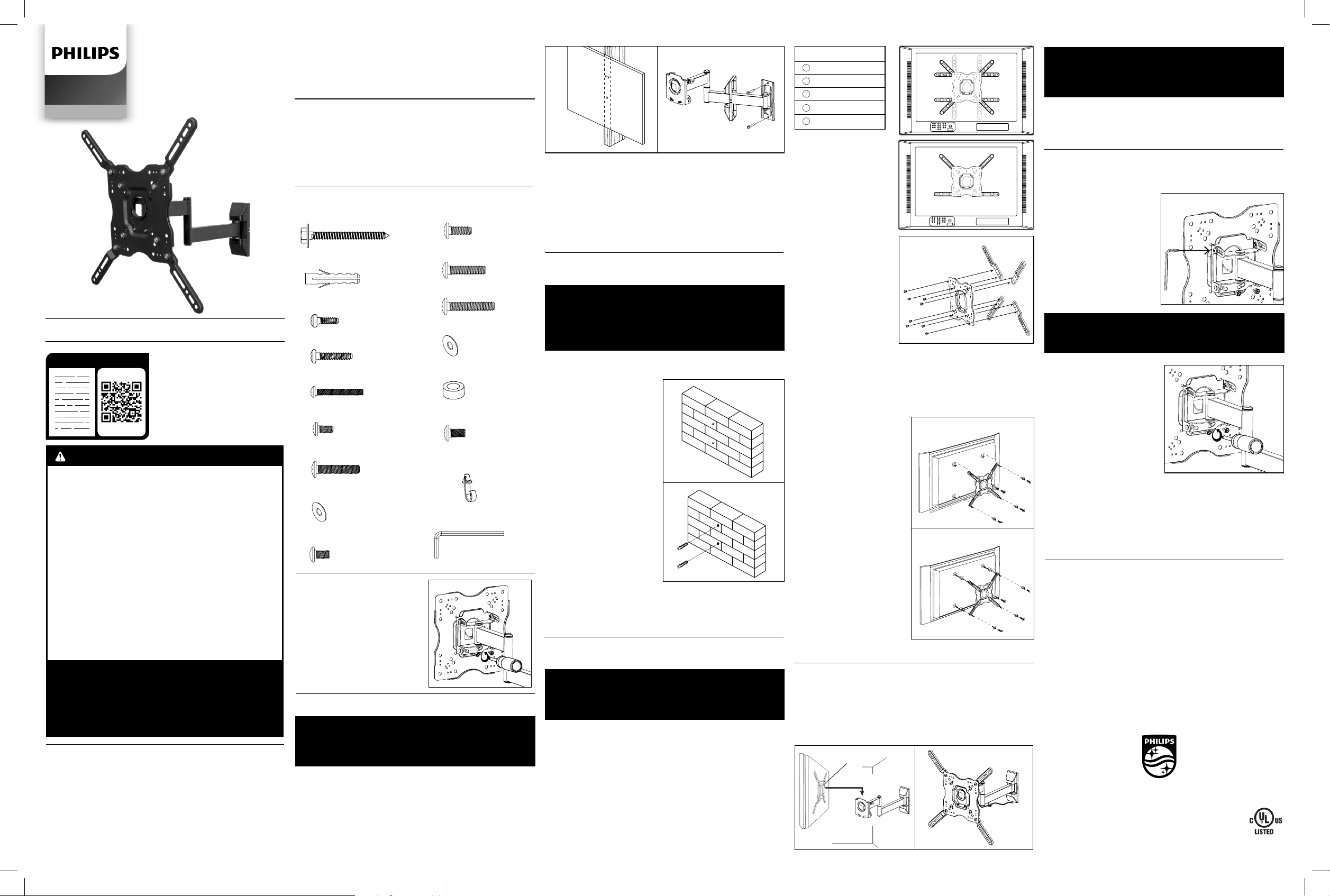
1. Examine the mounting holes on the back of your display:
A. If the mounting holes are spaced between 100mm x 100mm
and 200mm x 200mm apart, skip this section and proceed
with step 2.
B. If the mounting holes are spaced more than 200mm x
200mm apart, check the chart and illustrations above to
determine the correct orientation for attaching the adaptor
plates to the mount (see Fig. 6).
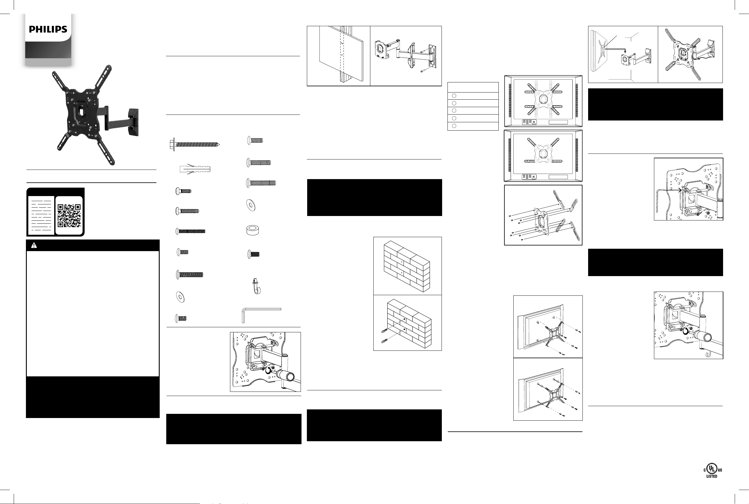
PART 3 – FINAL ASSEMBLY
1. To complete the installation, carefully place the display plate
with your display attached on the mount as shown
(see Fig. 9). Do not release the display until the display plate is
securely placed on the mount.
2. Replace the safety screws removed in part 1 and tighten.
BEFORE INSTALLING
Prepare the mount for installation
by disassembling the display
plate from the mount.
1. Remove the safety screws as
shown (see Fig. 1).
2. Place the screws in a safe
location.
OPERATION AND ADJUSTMENT
1. To change the tilt angle of your display, have one person hold
the display rmly in place while another person loosens the tilt
adjustment screws located
on each side of the mount
using the S4 Allen Key (Q)
from the hardware kit
(see Fig. 11). Once loosened,
you may move your display
to the desired position.
Re-tighten the screws to lock
the tilt angle in place. Do not
release the display until these
screws are fully tightened and
never fully loosen or remove
these screws.
IMPORTANT!
NEVER FULLY LOOSEN OR REMOVE THE TILT
ADJUSTMENT KNOB WHILE OPERATING THE MOUNT.
2. Swivel adjustments can be
made simply by moving your
display to the desired
position.
3. To make level correction
adjustments, have one person
hold the display rmly in place
while another person slightly
loosens the safety screws as
shown in the illustration using
the screw driver (see Fig. 12).
Rotate the screen until
level and then re-tighten the
safety screws. Never fully
loosen or remove these screws.
IMPORTANT!
THE SAFETY SCREWS MUST BE TIGHTENED AT ALL
TIMES TO PREVENT THE DISPLAY FROM BEING
ACCIDENTALLY KNOCKED FROM THE MOUNT.
3. Install the cable management clip (P) from Hardware Kit as
shown in the illustration (see Fig. 10). Cables can be routed
through the hook located on the mount to keep them organized
and out of the way. Slide the plastic cover back to the mount.
Read these instructions or
watch an easy-to-follow
video. Scan QR code or visit
http://bit.ly/2rdjEjj
3. While another person holds the mount in place, mark two
locations for securing the mount to the wall
(see Fig. 2).
4. Set the mount aside and drill a 3mm (1/8") pilot hole at each
marked location.
5. Place the mount back against the wall and attach it using
the screws (A) provided (see Fig. 3). Do not over-tighten these
screws. Ensure that the mount remains level after all screws
are secured.
SQM9442/27
Audio/Video
C. Attach the
adaptors on the display
plate as shown in the
appropriate illustration
using the M8 x 10 screws
(O) from the hardware kit
(see Fig. 7).
2. Determine the correct
length of screw to use by
again examining the back
of your display:
A.If the back of your
display is at and the
mounting holes are ush
with the surface, you
will use the shorter
screws (C, F or I) from
the hardware kit.
B. If the back of your
display is curved, has
a protrusion, or if the
mounting holes are
recessed, you will need to use the longer screws (D, E, G, J, K
or L) and may also need to use the spacers (N).
3. Determine the correct diameter of screw to use by carefully
trying one of each size (M4, M6 and M8) from the hardware
kit. Do not force any of the screws – if you feel resistance stop
immediately and try a smaller diameter screw.
4. Place the display plate
of the mount over the back
of your display and line it
up with the holes. Make
sure the arrow on the display
plate is pointing up.
5. Attach display plate to the
back of your display using the
screws identied in steps 1
and 2 (see Fig. 8):
A. If you are using the M4
or M6 screws you will need
to use the M6 washers (H).
If you are using the M8
screws you will need to
use the M8 Washers (M).
B. If you are using the
longer screws on a
display with a curved or
recessed back, you may
also need to use the
spacers (N). Use one
spacer or two spacers
stacked as needed.
Only use a spacer if
necessary.
Fig. 1
Fig. 7
INSPECT ALL SCREWS AND HARDWARE AT
REGULAR INTERVALS TO ENSURE THAT NO
CONNECTIONS HAVE BECOME LOOSE OVER
TIME. RETIGHTEN AS NEEDED.
HARDWARE KIT
(A) Screws (x2)
(B) Concrete Anchor (x2)
(C) M4 x 12 Screw (x4)
(D) M4 x 20 Screw (x4)
(E) M4 x 45 Screw (x4)
(F) M6 x 12 Screw (x8)
(G) M6 x 20 Screw (x4)
(H) M6 Washer (x4)
(I) M8 x 12 Screw (x4)
(J) M8 x 20 Screw (x4)
(K) M8 x 35 Screw (x4)
(L) M8 x 45 Screw (x4)
(M) M8 Washer (x4)
(N) Spacer (x8)
(O) M8 x 10 Screw (x8)
(Q) S4 Allen Key (x1)
(P) Cable Management
(x1)
13
33
3
1
2
5
2
5
2
5
2
5
11
33
33
1
1
11
44
44
Fig. 6
For displays with curved or
recessed
backs.
For displays with
at backs.
Fig. 8
Fig. 10
Fig. 9
Fig. 11
Fig. 12
READ IT OR WATCH IT
WARNINGS
1. Read these instructions before you begin. If you are
unsure of any part of the process, contact a professional
contractor or installer for assistance. Improper
installation can result in injury or damage.
2. The wall or mounting surface must be capable of
supporting the combined weight of the mount and the
display. If it will not, the structure must be reinforced.
3. Locate pipes, wires or any other hazards in the wall
where you wish to install the mount, before drilling.
4. Safety gear and proper tools must be used. Failure to
do so can result in injury or damage.
5. Two people are recommended for installation. Do not
attempt to lift a heavy display without assistance.
6. Follow all instructions and recommendations
regarding adequate ventilation and suitable locations
for mounting your display. For more information, consult
the owner’s manual for your particular display.
CAUTION: THIS WALL MOUNT IS INTENDED
FOR USE ONLY WITH THE MAXIMUM WEIGHT
OF 25KG (55 LBS).
USE WITH HEAVIER THAN THE MAXIMUM WEIGHT
INDICATED MAY RESULT IN INSTABILITY, PROPERTY
DAMAGE AND/OR POSSIBLE INJURY.
Mounting Pattern (W x H)
300 mm x 200 mm
300 mm x 300 mm
400 mm x 200 mm
400 mm x 300 mm
400 mm x 400 mm
1
2
3
4
5
Fig. 2 Fig. 3
Fig. 4
Fig. 5
HECHO EN CHINA
Philips y el emblema de escudo Philips son marcas
registradas de Koninklijke Philips N.V. y se usan bajo
licencia. Este producto ha sido fabricado y se comercializa
bajo responsabilidad de Jasco Products Company y Jasco
Products Company LLC, 10 E. Memorial Rd., Oklahoma City,
OK 73114, es el garante en relación a este producto.
Este producto tiene una garantía limitada de por vida.
Visite www.philips.com/support para conocer los detalles
de la garantía.
¿Tiene preguntas? Comuníquese al
1-844-816-0320 entre las 7AM - 8PM CST
(hora central estándar).
Lea estas instrucciones o mire
un video fácil de seguir. Escanee
este código de QR,
o visite http://bit.ly/2rdjEjj
Guía de instalación
2. Coloque la montaje de pared contra la pared sobre el viga
marcado
con la echa en la montaje de pared hacia arriba
.
Asegúrate de que está nivelado.
3.
Mientras otra persona sostiene
el montaje de pared
en
posición, marque dos puntos para asegurar el soporte de pared
a la pared (ver Fig. 2).
4.
Retire
el montaje de pared
y perfore un oricio piloto de
3 mm (1/8”) en cada punto marcado.
5. Vuelva a colocar la montaje de pared en la pared y fíjela con
los tirafondos (A) provistos (ver Fig. 3). No ajuste los tirafondos
en exceso. Asegúrese de que la montaje de pared esté nivelada
después de ajustar todos los tirafondos.
HERRAMIENTAS NECESARIAS
• Destornillador Phillips #2
• Taladro eléctrico o portátil
• Broca de 3 mm (1/8”) y detector de vigas para instalar
en placa de yeso
• Broca de 8 mm (5/16”) para instalar en
concreto/mampostería
• Un nivel
CONTENIDO DEL PAQUETE
Montaje en pared (x1) Guía de instalación
Adaptador (x4) Kit de tornillería
Plastic Cover (x2)
ESPECIFICACIONES
Tamaño de la pantalla: 22" to 80"
Carga máxima: 55lbs (25kg)
Patrón del soporte:
75mm x 75mm, 100mm x 100mm,
200mm x 100mm, 200mm x 200mm, 300mm x 300mm,
400mm x 400mm
Rango de inclinación: arriba 5° y abajo 15°
Rango de paneo y giro: hasta 180°
Perl: 2.6” a 17.5” (6.6cm a 44.5cm)
SQM9442/27
Audio/Video
KIT DE TORNILLERÍA
(A) Tornillos (x2)
(B) Anclaje para concreto
(x2)
(C) Tornillos M4 x 12 (x4)
(D) Tornillos M4 x 20 (x4)
(E) Tornillos M4 x 45 (x4)
(F) Tornillos M6 x 12 (x8)
(G) Tornillos M6 x 20 (x4)
(H) Arandela M6 (x4)
(I) Tornillos M8 x 12 (x4)
(J) Tornillos M8 x 20 (x4)
(K) Tornillos M8 x 35 (x4)
(L) Tornillos M8 x 45 (x4)
(M) Arandela M8 (x4)
(N) Espaciador (x8)
(O) Tornillos M8 x 10 (x8)
(Q) Llave Allen S4 (x1)
(P) Clip de gestión de
cables (x1)
PARTE 1A: INSTALACIÓN EN UNA PLACA
DE YESO
IMPORTANTE!
POR MOTIVOS DE SEGURIDAD,
ESTE EL
SOPORTE DEBE ESTAR ASEGURADO A UN MONTANTE DE
MADERA CAPAZ DE SOPORTAR EL PESO COMBINADO
DEL SOPORTE Y LA PANTALLA. NO LO INSTALE SOLO EN
PLACAS DE YESO.
1. Usar un detector de vigas de buena calidad para localizar la
uno viga donde desea instalar el montaje de pared. Marque
los dos extremos de cada viga para poder identicar el centro
exacto.
NOTA: Debe usar el centro de la viga para evitar roturas o
agrietamientos en la madera durante la instalación.
ANTES DE INSTALAR
Prepare
la montaje de
pared
para la instalación
desmontando la placa de
la montaje
.
1. Retire los tornillos de
seguridad como se
muestra (ver Fig. 1).
2. Coloque los tornillos
en un lugar seguro.
Fig. 1
Fig. 2 Fig. 3
LÉELO O MÍRALO
PARTE 1B: INSTALACIÓN EN CONCRETO/
MAMPOSTERÍA
IMPORTANTE!
POR MOTIVOS DE SEGURIDAD, LA PARED DE CONCRETO
DEBE PODER SOPORTAR EL PESO COMBINADO
DEL SOPORTE Y LA PANTALLA. EL FABRICANTE NO
SE RESPONSABILIZA POR EL DAÑO QUE PUDIERAN
OCASIONAR LAS PAREDES POCO RESISTENTES.
1. Coloque la montaje de pared contra la pared sobre el viga
marcado
con la echa en la montaje de pared hacia arriba
.
Asegúrate de que está nivelado.
2.
Mientras otra persona
sostiene
el montaje de
pared
en posición, marque
dos puntos para asegurar el
soporte de pared a la pared
(ver Fig. 4).
3.
Retire
el montaje de pared
y perfore un oricio piloto de
8 mm (5/16”) en cada punto
marcado. Eliminar el polvo de
los agujeros.
4. Introduzca un anclaje
para concreto (B) en cada
oricio hasta que queden
al ras de la supercie de
concreto (ver Fig. 5).
Si fuera necesario, pueden
darse golpes leves con un
martillo para colocar los
anclajes en su lugar.
NOTA: Si la pared de concreto
tiene un revestimiento de yeso
o revoque, el anclaje para
concreto debe traspasar por completo esta capa hasta
queda al ras de la supercie de concreto.
5.
Vuelva a colocar la montaje de pared en la pared y fíjela
con los tirafondos (A) provistos (ver Fig. 5). No ajuste los
tirafondos en exceso. Asegúrese de que la montaje de pared
esté nivelada después de ajustar todos los tirafondos.
PARTE 2 – COLOCACIÓN DE LOS BRAZOS DEL
SOPORTE EN LA PANTALLA
IMPORTANTE! TENGA ESPECIAL CUIDADO
DURANTE ESTA PARTE DE LA INSTALACIÓN.
SI ES POSIBLE, EVITE COLOCAR LA PANTALLA HACIA
ABAJO, YA QUE PUEDE DAÑAR LA SUPERFICIE DE
VISUALIZACIÓN.
NOTA: Este soporte viene con una selección de distintos
diámetros y longitudes de tornillos para ajustar a una
gran variedad de modelos de pantalla. No usará todos los
componentes del kit de equipo. Si no puede encontrar el tamaño
de tornillo adecuado en el kit, consulte con el fabricante de la
pantalla para obtener más información.
1. Inspeccione los agujeros de montaje en la parte posterior
de su pantalla:
A.
Si los oricios de montaje están separados 100 mm x 100
mm o 200 mm x 200 mm, omita esta sección y continúe con
el paso 2.
B. Si los oricios de montaje están separados más de 200 mm
x 200 mm, revise el cuadro y las ilustraciones a continuación
para determinar la orientación correcta para unir las placas
adaptadoras al montaje (ver Fig. 6).
13
33
3
1
2
5
2
5
2
5
2
5
11
33
33
1
1
11
44
44
C. Fije los
adaptadores en la
placa de la pantalla
como se muestra en la
ilustración apropiada
usando los tornillos
M8 x 10 (O) del kit de
hardware (ver Fig. 7).
2. Determine la longitud
correcta del tornillo a
utilizar examinando la
parte posterior de su
pantalla:
A.Si la parte posterior
de la pantalla es
plana y los oricios de
montaje están
alineados con la
supercie, utilizará los
tornillos más cortos
(C, F o I) del kit de
hardware.
B. Si la parte posterior
de su pantalla es curva, tiene una protuberancia o los
oricios de montaje están retraídos, deberá usar los tornillos
más largos (D, E, G, J, K o L) y podría necesitar
los espaciadores (N).
3. Pruebe un tornillo de cada tamaño (M4, M6 y M8) provisto
en el kit para determinar el diámetro correcto que debe utilizar.
No fuerce los tornillos. Si percibe resistencia, DETÉNGASE y
pruebe con un tornillo de menor diámetro.
Para las pantallas con parte
posterior curva o
retraída
Para las pantallas
con parte posterior
plana
Fig. 8
4. Coloque la placa de la
pantalla del montaje sobre la
parte posterior de su pantalla
y alinéela con los agujeros.
Asegúrese de que la echa
en la placa de la pantalla esté
apuntando hacia arriba.
5. Fije la placa de la
pantalla a su pantalla con los
tornillos identicados en los
pasos 1 y 2 (ver Fig. 8):
A.Si usa tornillos M4 y M6,
también necesitará usar las
arandelas M6 (I). Si está
utilizando tornillos M8, use
las arandelas M8 (N).
B. Si está utilizando los
tornillos más largos en una
pantalla con una parte
posterior curva o empotrada,
es posible que también deba
usar los espaciadores (N).
Use un espaciador o dos
espaciadores apilados
según sea necesario.
Solo use un espaciador si es necesario.
PARTE 3: ENSAMBLAJE FINAL
1. Para completar la instalación, coloque cuidadosamente la
placa de la pantalla, con su pantalla conectada, en el ontaje de
pared como se muestra (ver Fig. 9). No suelte la pantalla hasta
que la placa de la pantalla esté colocada de forma segura en el
montaje de pared.
2. Vuelva a colocar los tornillos de seguridad retirados en la
parte 1 y apriete.
Fig. 10
Fig. 9
OPERACIÓN Y AJUSTE
1. Para cambiar el ángulo de
inclinación de su pantalla,
haga
que una persona lo
sostenga rmemente en su
lugar mientras
otra persona
aoja los tornillos de ajuste
de inclinación ubicados a
cada lado del soporte usando
la Llave Allen S4 (Q) del kit de
hardware (ver Fig. 11). Una vez
que se aojan los tornillos,
puede mover su pantalla a la
posición deseada. Vuelva a apretar los tornillos para bloquear
el ángulo de inclinación en su lugar. No suelte la pantalla hasta
que estos tornillos están completamente apretados y nunca los
aoje o retire por completo.
IMPORTANTE!
NUNCA AFLOJE O RETIRE COMPLETAMENTE LA
PERILLA DE AJUSTE DE INCLINACIÓN MIENTRAS OPERA
EL MONTAJE DE PARED.
2. Los ajustes de giro se pueden hacer simplemente moviendo
la pantalla a la posición deseada.
3. Para realizar ajustes de
corrección de nivel, haga que
una persona sostenga
la pantalla rmemente en
su lugar mientras otra
persona aoja ligeramente
los tornillos de seguridad
como se muestra en la
ilustración usando el
destornillador (ver Fig. 12).
Gire la pantalla hasta el
nivel y luego vuelva a
apretar los tornillos de
seguridad. Nunca aoje o
retire completamente estos
tornillos.
IMPORTANTE!
LOS TORNILLOS DE SEGURIDAD DEBEN ESTAR
APRETADOS EN TODO MOMENTO PARA EVITAR QUE
LA PANTALLA SE CAIGA ACCIDENTALMENTE DEL
SOPORTE.
3. Instale el clip de administración de cables (P) del kit de
hardware como se muestra en la ilustración (ver Fig. 10). Los
cables se pueden pasar a través del gancho ubicado en el
montaje para mantenerlos limpios y fuera del camino. Deslice la
cubierta de plástico hacia el soporte.
Fig. 11
REVISE TODOS LOS TORNILLOS Y EL EQUIPO CON
FRECUENCIA PARA ASEGURARSE DE QUE LAS
CONEXIONES NO SE AFLOJARON CON EL PASO DEL
TIEMPO. VUELVA A AJUSTAR SEGÚN SEA NECESARIO.
Fig. 12
ADVERTENCIAS
1. Lea estas instrucciones antes de comenzar. Si tiene
dudas acerca de alguna parte del proceso, comuníquese
con un contratista o instalador profesional para recibir
ayuda. La instalación incorrecta podría ocasionar daños
o lesiones.
2. La pared o la supercie de montaje deben poder
soportar el peso combinado del soporte y la pantalla. De
lo contrario, se deberá reforzar la estructura.
3. Antes de hacer las perforaciones, ubique las tuberías,
los cables y cualquier otro peligro que haya en la pared en
la que desea instalar el soporte.
4. Deberá usar equipo de seguridad y las herramientas
adecuadas. De lo contrario, podrían producirse daños o
lesiones.
5. Se recomienda que dos personas realicen la instalación.
No intente levantar una pantalla pesada sin ayuda.
6. Siga todas las instrucciones y recomendaciones sobre
la correcta ventilación y las ubicaciones más apropiadas
para la instalación de la pantalla. Si desea obtener más
información, consulte el Manual de usuario de su modelo
de pantalla.
PRECAUCIÓN: ESTE SOPORTE DE PARED
ESTÁ DISEÑADO PARA USARSE SOLO CON
EL PESO MÁXIMO DE 25 KG (55 LB).
EL USO DE UN PESO SUPERIOR AL MÁXIMO INDICADO
PUEDE PROVOCAR INESTABILIDAD, DAÑAR LOS
OBJETOS O CAUSAR POSIBLES LESIONES.
Fig. 6
300 mm x 200 mm
300 mm x 300 mm
400 mm x 200 mm
400 mm x 300 mm
400 mm x 400 mm
1
2
3
4
5
Patrón de Montaje
(W x H)
Fig. 7
Fig. 4
Fig. 5