Loading ...
Loading ...
Loading ...
4
STEP 1 - CABINET OR WALL OPENING
The opening in the wall or cabinet must be within the following
dimensions:
OPENING SKM427F9HS SKM430F9HS
A 24
3
/4" (628.7 mm) 24
3
/4" (628.7 mm)
Width (B) 27
1
/8" (689 mm) 30
1
/4" (768.4 mm)
Height (C) 22
7
/16" (569.9 mm) 22
7
/16" (569.9 mm)
D 1
3
/16" (30.2 mm) 2
11
/16" (67.5 mm)
E 3
1
/4" (82 mm) 3
1
/4" (82 mm)
F 1
1
/2" (38.8 mm) 1
1
/2" (38.8 mm)
G 4" (101.6 mm) 4" (101.6 mm)
Minimum
Depth (I)
20" (508 mm) 20" (508 mm)
Outlet should NOT be in the shaded area H as indicated in
Figure 1.
Mounting
cleat
F
B
A
E
D D
Top View
Front View
Shelf
Shelf
Cabinet
face
Bottom of flush cutout
H
C
B
I
G
G
Figure 1
NOTES
Dimension C above will result in 1
1
⁄4" (31.8 mm) spaces
above and below the trim to allow for necessary intake and
exhaust air ow to ensure appliance does not overheat. Do
not reduce this spacing as doing so will void the warranty
for any issues resulting from a lack of airow.
NOTES
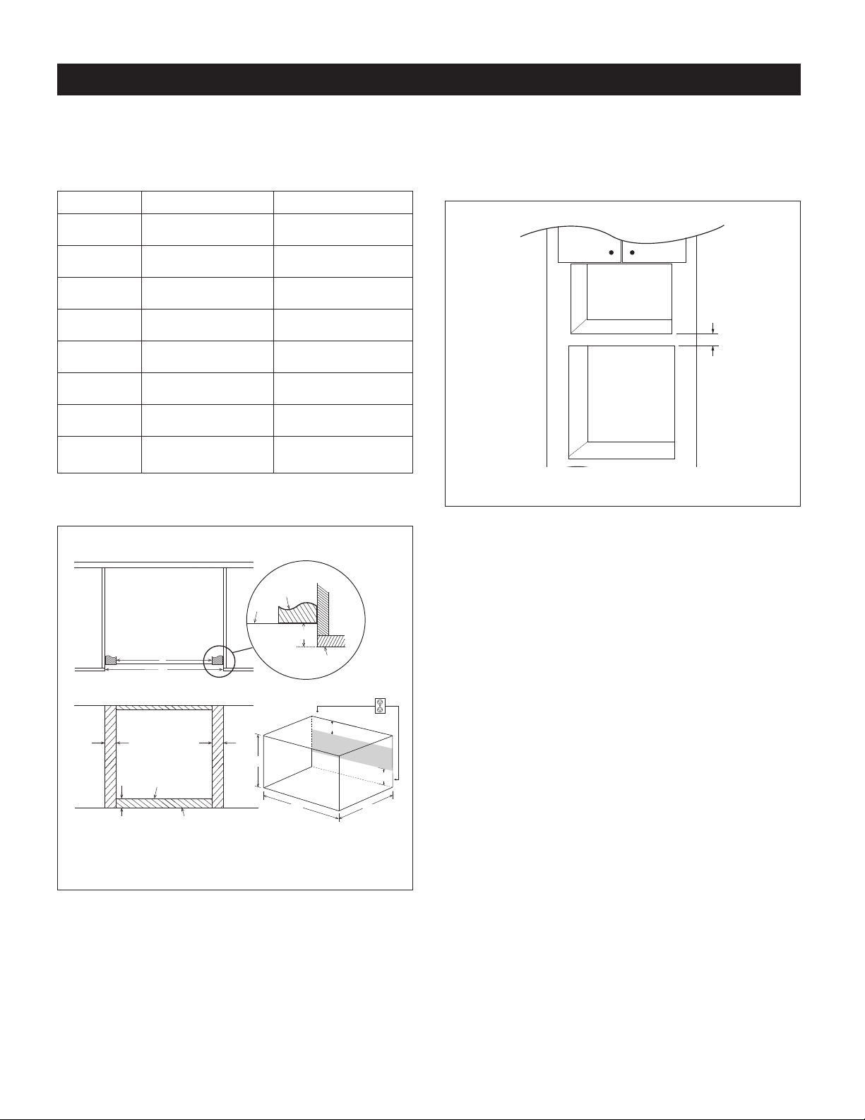
• Allow minimum 3" (76 mm) wood gap between the
microwaveovencutoutandtheappliancecutoutbelow
themicrowaveoven.SeeFigure2.
3" Min
.
Microwave cutout
Wall oven cutout
Figure 2
• Theooroftheopeningshouldbeconstructedofplywood
strongenoughtosupporttheweightoftheovenandoor
load(about100lb/45kg).Theoorshouldbeleveland
90˚withthefaceofthecabinetforproperinstallationand
operationoftheoven.Checkthelocalbuildingcodethat
may require that the opening be enclosed with sides,
ceiling and rearpartition. The properfunctioning of the
ovendoesnotrequiretheenclosure.
FLUSH INSTALLATION INSTRUCTIONS
Loading ...
Loading ...
Loading ...