Loading ...
Loading ...
3
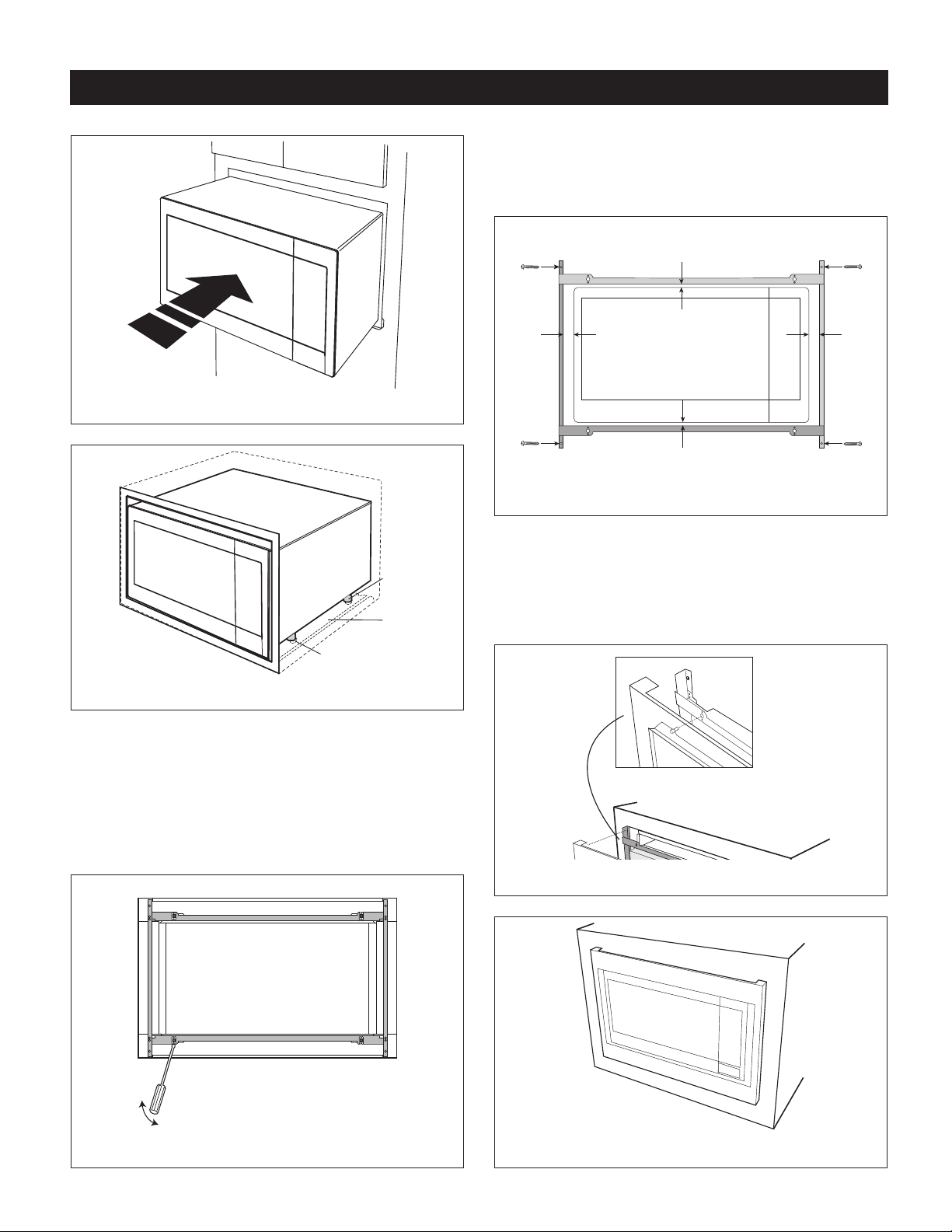
FIGURE 4
Exhaust
duct
assembly
Foot
Duct recess
FIGURE 5
3.DISASSEMBLY:The FRONT FRAMEand BACK FRAME
come pre-assembled with ball studs engaged in the
receivers.Separate the FRONT FRAME from the BACK
FRAME.Placetheassemblyfacedownontoaprotected
surface.Atthelocationoftheballstud,insertaathead
screwdriverbetweentheFRONTFRAMEandtheBACK
FRAMEandgentlypryuptodisengagetheballstudfrom
thereceiver.Repeatforeachcorner.SeeFigure6.
FIGURE 6
STANDARD INSTALLATION INSTRUCTIONS
4.BACK FRAME INSTALLATION: Position BACK FRAME
withequalspacetoptobottom,sidetoside.Markfor4
holes, center punch and pre-drill the cabinet with
1
/16"
drillbit.Secureframewith4SCREWSE.SeeFigure7.
Equal gap top, bottom
Equal gap
side to side
Mounting holes
Mounting holes
Mounting holes
Mounting holes
Screw E
Screw E
Screw E
Screw E
FIGURE 7
5.FRONT FRAME INSTALLATION: Place the FRONT
FRAME onto the BACK FRAME and align ball studs
and receivers. Securethe FRONT FRAME to the BACK
FRAME by rmly pushing the FRONT FRAME onto the
BACK FRAME engaging the 4 snap attachments. See
Figures8and9.
FIGURE 8
FIGURE 9
Loading ...
Loading ...
Loading ...