Loading ...
2
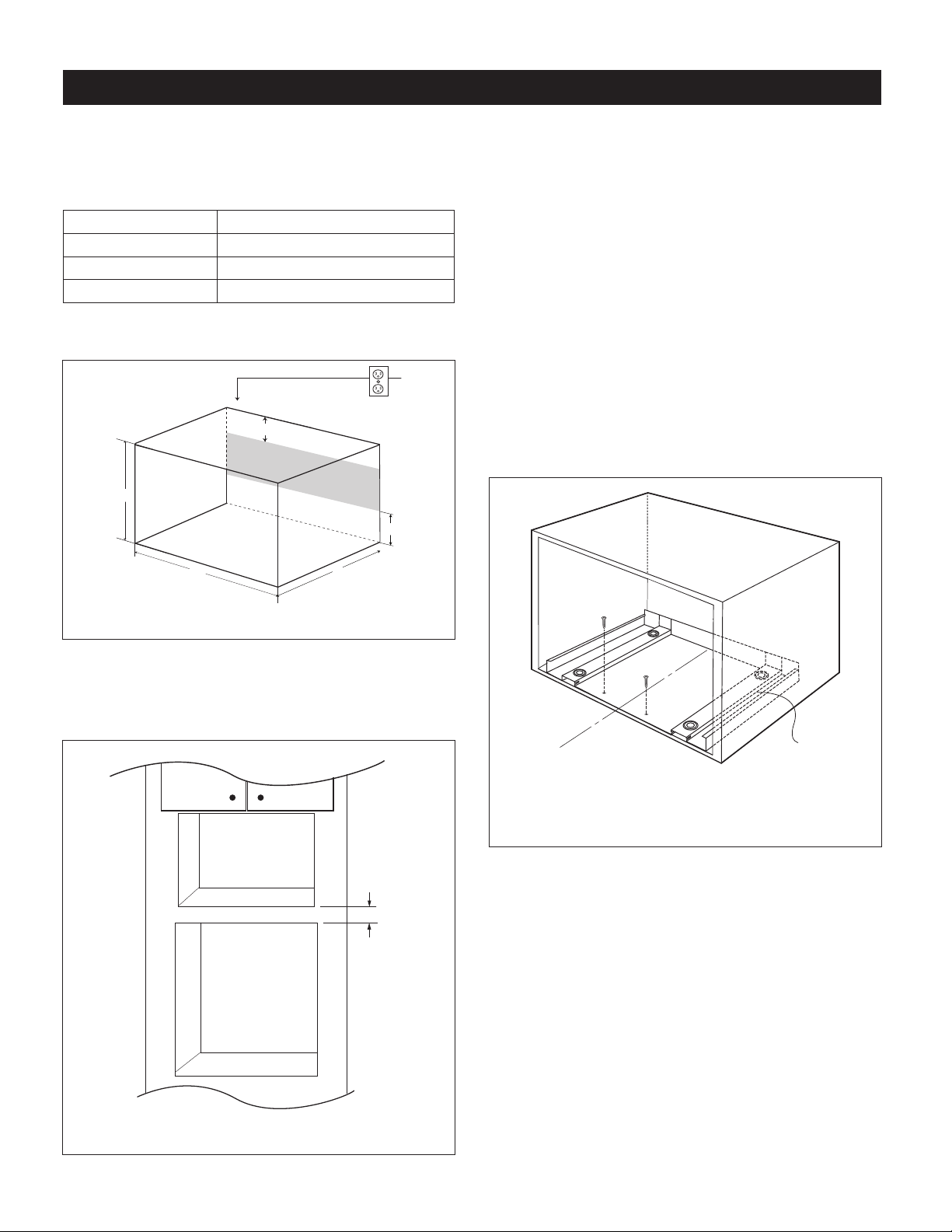
STEP 1 - CABINET OR WALL OPENING
The opening in the wall or cabinet must be within the following
dimensions:
OPENING SKM427F9HS, SKM430F9HS
Height (A) 14
1
/2" - 15
3
/4" (368.3 - 400 mm)
Width (B) 24
3
/4" (628.7 mm)
Minimum Depth (C) 20" (508 mm)
Outlet should NOT be in the shaded area as indicated in
Figure 1.
A
B
4"
C
4"
FIGURE 1
NOTES
• Please allow minimum 3" wood gap between the
microwaveovencutoutandtheappliancecutoutbelow
themicrowaveoven.SeeFigure2.
3" Min.
Microwave cutout
Wall oven cutout
FIGURE 2
• If the dimension of DEPTH (C) is more than 21" (533.4
mm),theoutletlocationmaybeanyareaontherearwall.
• Theooroftheopeningshouldbeconstructedofplywood
strongenoughtosupporttheweightoftheovenandoor
load(about100lb/45kg).Theoorshouldbeleveland
90˚withthefaceofthecabinetforproperinstallationand
operationoftheoven.Checkthelocalbuildingcodethat
mayrequiretheopeningbeenclosedwithsides,ceiling
and rear partition. The proper functioning of the oven
doesnotrequiretheenclosure.
STEP 2 - EXHAUST DUCT ASSEMBLY INSTALLATION
1.Placethe EXHAUSTDUCT ASSEMBLYinthe centerof
theopening.Alignthefrontedgeoftheductwiththefront
ofthecabinet.
2.SecuretheEXHAUSTDUCTASSEMBLYwith2SCREWS
D.SeeFigure3.
C
L
Exhaust duct
assembly, align
to front edge of
cabinet
Screw D
Screw D
FIGURE 3
STEP 3 - FRAME INSTALLATION
1.Placetheovenadjacenttothewallorcabinetopening.
PlugthePOWERCORDintotheelectricaloutlet.
2.Carefully guide the assembled oven into the prepared
opening. Slide the oven onto the EXHAUST DUCT
ASSEMBLY.Avoidpinching thecord between theoven
andthewall.SeeFigure4.
Adjust the position of the oven so the feet of the oven
are tted into the recesses of the EXHAUST DUCT
ASSEMBLYandthedooropensproperly.SeeFigure5.
STANDARD INSTALLATION INSTRUCTIONS
Loading ...
Loading ...
Loading ...