1
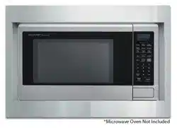
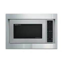
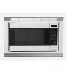
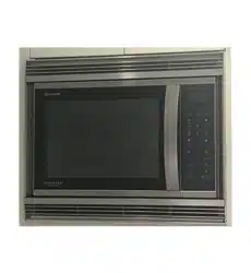
For Sharp Carousel
®
Built-in Kit
Models SKM427F9HS or SKM430F9HS
S = STAINLESS
THIS KIT IS UL APPROVED TO ALLOW CERTAIN
MICROWAVE OVENS TO BE INSTALLED ABOVE ANY
ELECTRIC WALL OVEN. REFER TO OVEN OPERATION
MANUAL.
IMPORTANT:
This Built-in Kit is designed for and approved only for those
Sharp Microwave Ovens specifying Built-In Kit SKM427F9HS
or SKM430F9HS. Refer to oven Operation Manual.
IMPORTANT NOTES TO THE INSTALLER
• PLEASE READ THESEINSTRUCTIONSTHOROUGHLY
BEFOREBEGINNINGINSTALLATION.
• Observe all governing codes, ordinances and safety
instructions.
• Leavetheseinstructionswiththeconsumer.
• DISCONNECTTHEPLUGofthemicrowaveovenfromthe
electricaloutletbeforeinstallingtheBuilt-inKit.Remove
theCarouselturntablefromtheovencavity.
• Becausethekitincludesmetalparts,duecautionshould
beusedinhandlingandinstallationtoavoidthepossibil-
ityofinjury.
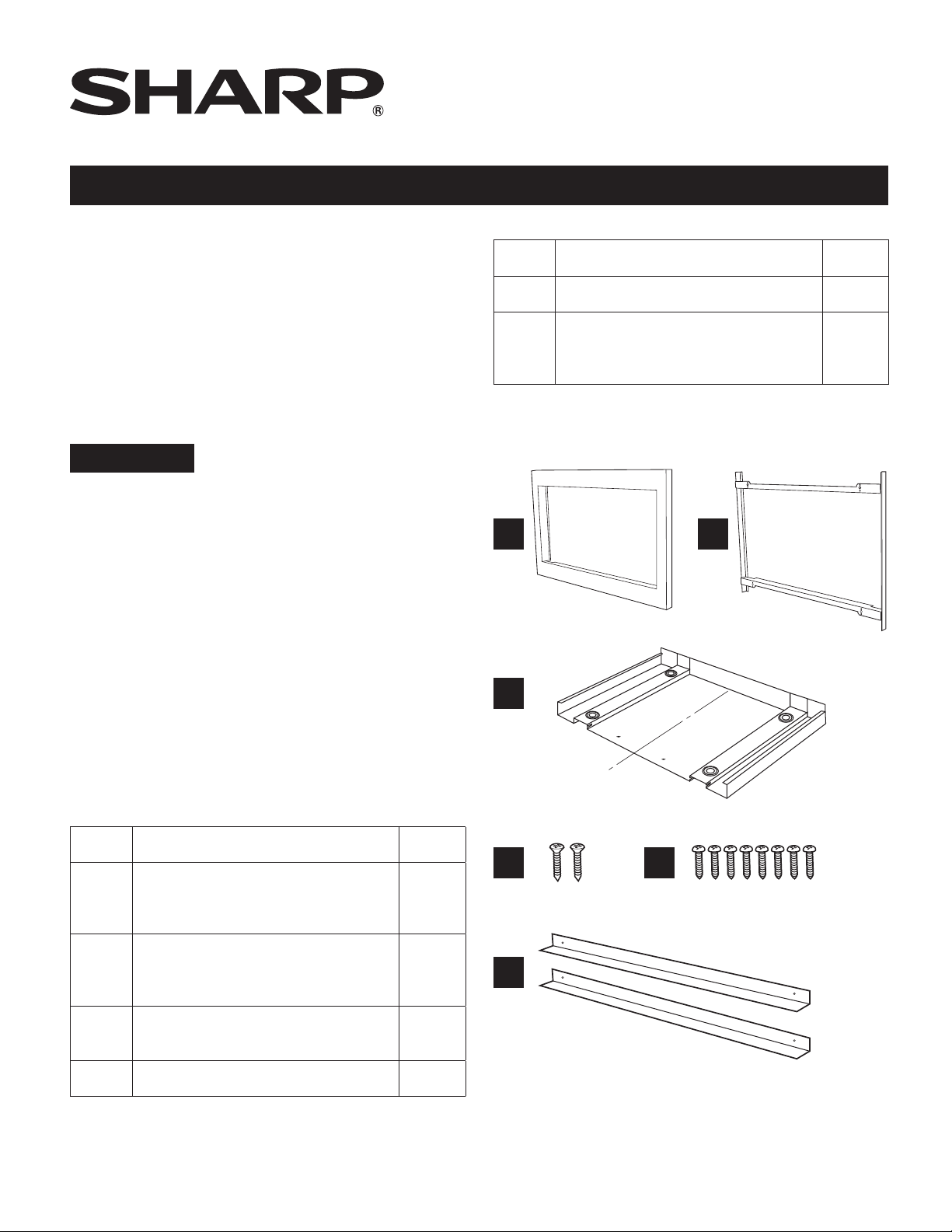
ITEM PART NAME QTY
A
FRONTFRAME
SKM427F9HS:FDECAB283MRK0
SKM430F9HS:FDECAB282MRK0
1
B
BACKFRAME
SKM427F9HS:FDECAB255MRK0
SKM430F9HS:FDECAB255MRK0
1
C
EXHAUSTDUCTASSEMBLY
PDUC-B200MRP1
1
D SCREWD:XTSS740P20000 2
INSTALLATION INSTRUCTIONS
A B
D
F
C
E
ITEM PART NAME QTY
E SCREWE:XOPS740P16000 8
F
AIRDEFLECTOR:
SKM427F9HS:PREF-B038MRP0
SKM430F9HS:PREF-B039MRP0
2
C
L
2
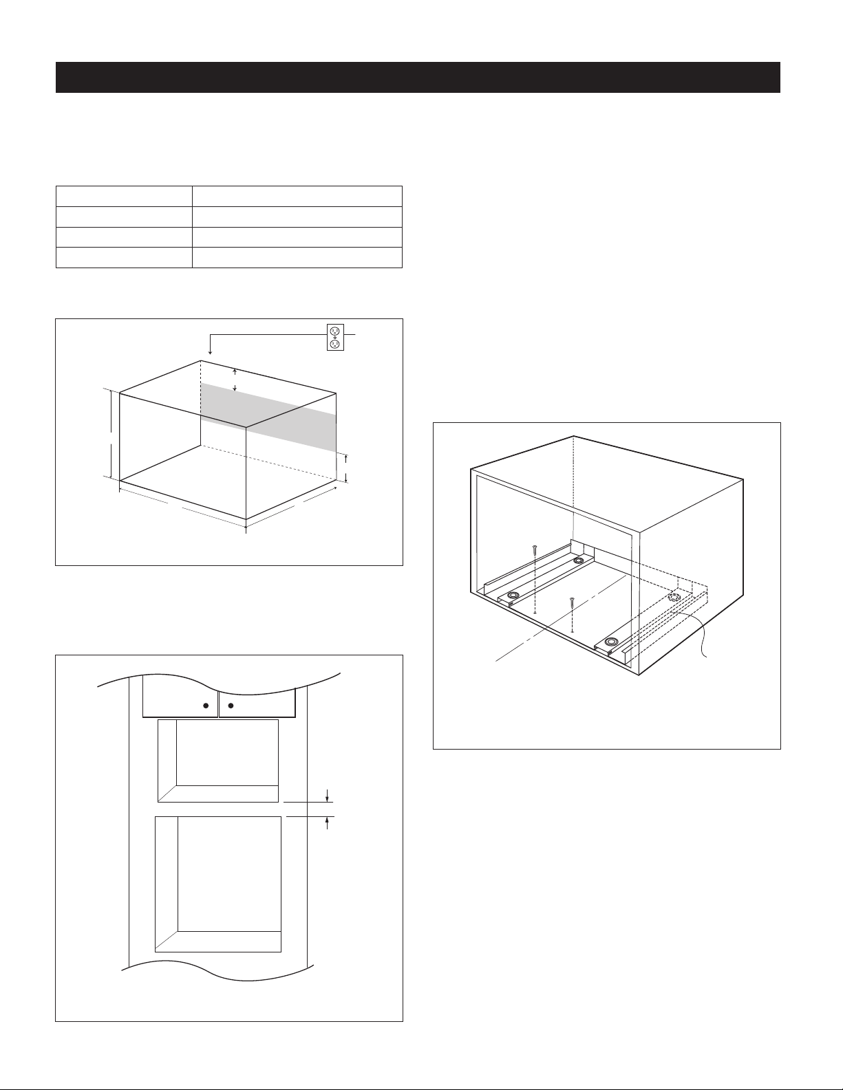
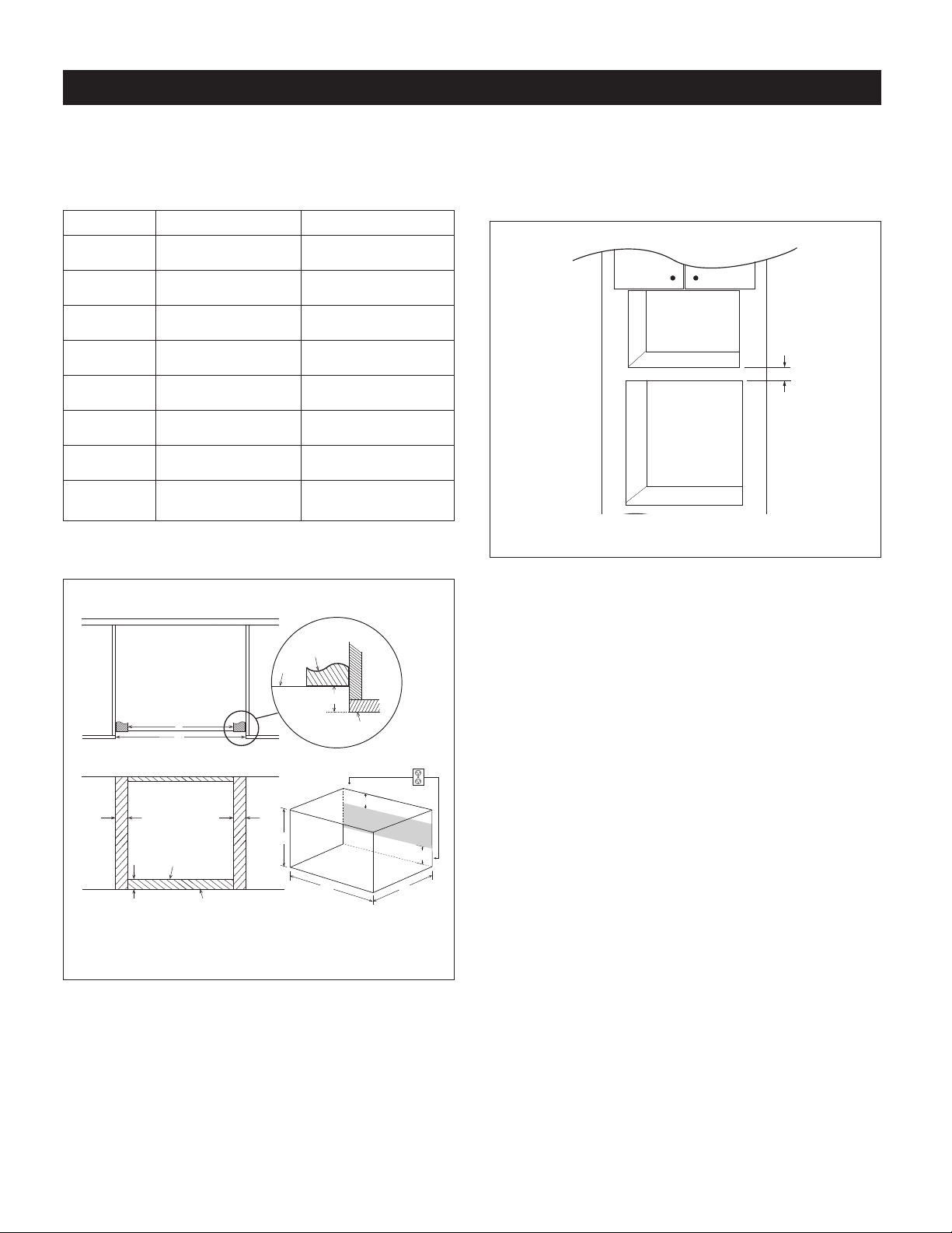
STEP 1 - CABINET OR WALL OPENING
The opening in the wall or cabinet must be within the following
dimensions:
OPENING SKM427F9HS, SKM430F9HS
Height (A) 14
1
/2" - 15
3
/4" (368.3 - 400 mm)
Width (B) 24
3
/4" (628.7 mm)
Minimum Depth (C) 20" (508 mm)
Outlet should NOT be in the shaded area as indicated in
Figure 1.
A
B
4"
C
4"
FIGURE 1
NOTES
• Please allow minimum 3" wood gap between the
microwaveovencutoutandtheappliancecutoutbelow
themicrowaveoven.SeeFigure2.
3" Min.
Microwave cutout
Wall oven cutout
FIGURE 2
• If the dimension of DEPTH (C) is more than 21" (533.4
mm),theoutletlocationmaybeanyareaontherearwall.
• Theooroftheopeningshouldbeconstructedofplywood
strongenoughtosupporttheweightoftheovenandoor
load(about100lb/45kg).Theoorshouldbeleveland
90˚withthefaceofthecabinetforproperinstallationand
operationoftheoven.Checkthelocalbuildingcodethat
mayrequiretheopeningbeenclosedwithsides,ceiling
and rear partition. The proper functioning of the oven
doesnotrequiretheenclosure.
STEP 2 - EXHAUST DUCT ASSEMBLY INSTALLATION
1.Placethe EXHAUSTDUCT ASSEMBLYinthe centerof
theopening.Alignthefrontedgeoftheductwiththefront
ofthecabinet.
2.SecuretheEXHAUSTDUCTASSEMBLYwith2SCREWS
D.SeeFigure3.
C
L
Exhaust duct
assembly, align
to front edge of
cabinet
Screw D
Screw D
FIGURE 3
STEP 3 - FRAME INSTALLATION
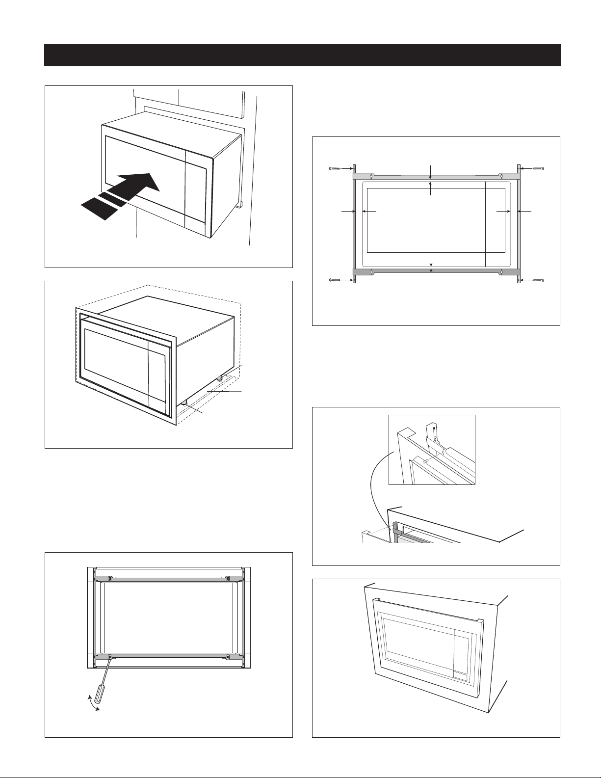
1.Placetheovenadjacenttothewallorcabinetopening.
PlugthePOWERCORDintotheelectricaloutlet.
2.Carefully guide the assembled oven into the prepared
opening. Slide the oven onto the EXHAUST DUCT
ASSEMBLY.Avoidpinching thecord between theoven
andthewall.SeeFigure4.
Adjust the position of the oven so the feet of the oven
are tted into the recesses of the EXHAUST DUCT
ASSEMBLYandthedooropensproperly.SeeFigure5.
STANDARD INSTALLATION INSTRUCTIONS
3
FIGURE 4
Exhaust
duct
assembly
Foot
Duct recess
FIGURE 5
3.DISASSEMBLY:The FRONT FRAMEand BACK FRAME
come pre-assembled with ball studs engaged in the
receivers.Separate the FRONT FRAME from the BACK
FRAME.Placetheassemblyfacedownontoaprotected
surface.Atthelocationoftheballstud,insertaathead
screwdriverbetweentheFRONTFRAMEandtheBACK
FRAMEandgentlypryuptodisengagetheballstudfrom
thereceiver.Repeatforeachcorner.SeeFigure6.
FIGURE 6
STANDARD INSTALLATION INSTRUCTIONS
4.BACK FRAME INSTALLATION: Position BACK FRAME
withequalspacetoptobottom,sidetoside.Markfor4
holes, center punch and pre-drill the cabinet with
1
/16"
drillbit.Secureframewith4SCREWSE.SeeFigure7.
Equal gap top, bottom
Equal gap
side to side
Mounting holes
Mounting holes
Mounting holes
Mounting holes
Screw E
Screw E
Screw E
Screw E
FIGURE 7
5.FRONT FRAME INSTALLATION: Place the FRONT
FRAME onto the BACK FRAME and align ball studs
and receivers. Securethe FRONT FRAME to the BACK
FRAME by rmly pushing the FRONT FRAME onto the
BACK FRAME engaging the 4 snap attachments. See
Figures8and9.
FIGURE 8
FIGURE 9
4
STEP 1 - CABINET OR WALL OPENING
The opening in the wall or cabinet must be within the following
dimensions:
OPENING SKM427F9HS SKM430F9HS
A 24
3
/4" (628.7 mm) 24
3
/4" (628.7 mm)
Width (B) 27
1
/8" (689 mm) 30
1
/4" (768.4 mm)
Height (C) 22
7
/16" (569.9 mm) 22
7
/16" (569.9 mm)
D 1
3
/16" (30.2 mm) 2
11
/16" (67.5 mm)
E 3
1
/4" (82 mm) 3
1
/4" (82 mm)
F 1
1
/2" (38.8 mm) 1
1
/2" (38.8 mm)
G 4" (101.6 mm) 4" (101.6 mm)
Minimum
Depth (I)
20" (508 mm) 20" (508 mm)
Outlet should NOT be in the shaded area H as indicated in
Figure 1.
Mounting
cleat
F
B
A
E
D D
Top View
Front View
Shelf
Shelf
Cabinet
face
Bottom of flush cutout
H
C
B
I
G
G
Figure 1
NOTES
Dimension C above will result in 1
1
⁄4" (31.8 mm) spaces
above and below the trim to allow for necessary intake and
exhaust air ow to ensure appliance does not overheat. Do
not reduce this spacing as doing so will void the warranty
for any issues resulting from a lack of airow.
NOTES
• Allow minimum 3" (76 mm) wood gap between the
microwaveovencutoutandtheappliancecutoutbelow
themicrowaveoven.SeeFigure2.
3" Min
.
Microwave cutout
Wall oven cutout
Figure 2
• Theooroftheopeningshouldbeconstructedofplywood
strongenoughtosupporttheweightoftheovenandoor
load(about100lb/45kg).Theoorshouldbeleveland
90˚withthefaceofthecabinetforproperinstallationand
operationoftheoven.Checkthelocalbuildingcodethat
may require that the opening be enclosed with sides,
ceiling and rearpartition. The properfunctioning of the
ovendoesnotrequiretheenclosure.
FLUSH INSTALLATION INSTRUCTIONS
5
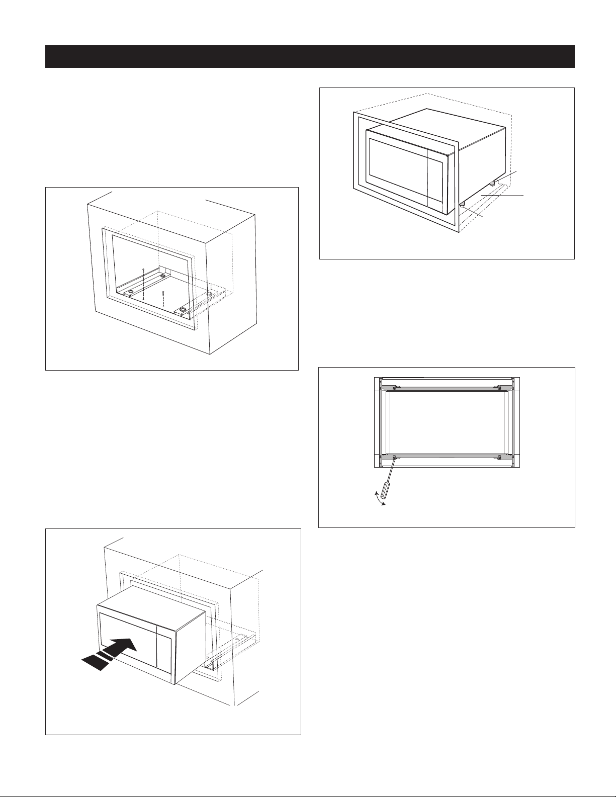
STEP 2 - EXHAUST DUCT ASSEMBLY INSTALLATION
1.Place the Exhaust Duct Assembly in the center of the
opening. Align the frontedge of the duct with the front
ofthecabinet.Alignthefrontedgeoftherightsideofthe
ductwiththefrontoftheshelf.SeeFigure3.
2.Secure the Exhaust Duct Assembly with 2 SCREWS D.
SeeFigure3.
Screw D
Screw D
Figure 3
STEP 3 - FRAME INSTALLATION
1.Place theoven adjacentto thewall or cabinetopening.
Plugthepowercordintotheelectricaloutlet.
2.Carefully guide the assembled oven into the prepared
opening. Slide the oven onto the EXHAUST DUCT
ASSEMBLY. Avoid pinching the cord between the oven
andthewall.SeeFigure4.
Adjustthepositionoftheovensothefeetoftheovenare
ttedintotherecessesoftheEXHAUSTDUCTASSEMBLY
andthedooropensproperly.SeeFigure5.
Screw D
Screw D
Figure 4
FLUSH INSTALLATION INSTRUCTIONS
Exhaust
duct
assembly
Foot
Duct recess
Figure 5
3.DISASSEMBLY:The FRONT FRAMEand BACK FRAME
come pre-assembled with ball studs engaged in the
receivers.Separate the FRONT FRAME from the BACK
FRAME.Placetheassemblyfacedownontoaprotected
surface.Atthelocationoftheballstud,insertaathead
screwdriverbetweentheFRONTFRAMEandtheBACK
FRAMEandgentlypryuptodisengagetheballstudfrom
thereceiver.Repeatforeachcorner.SeeFigure6.
Figure 6
6
FLUSH INSTALLATION INSTRUCTIONS
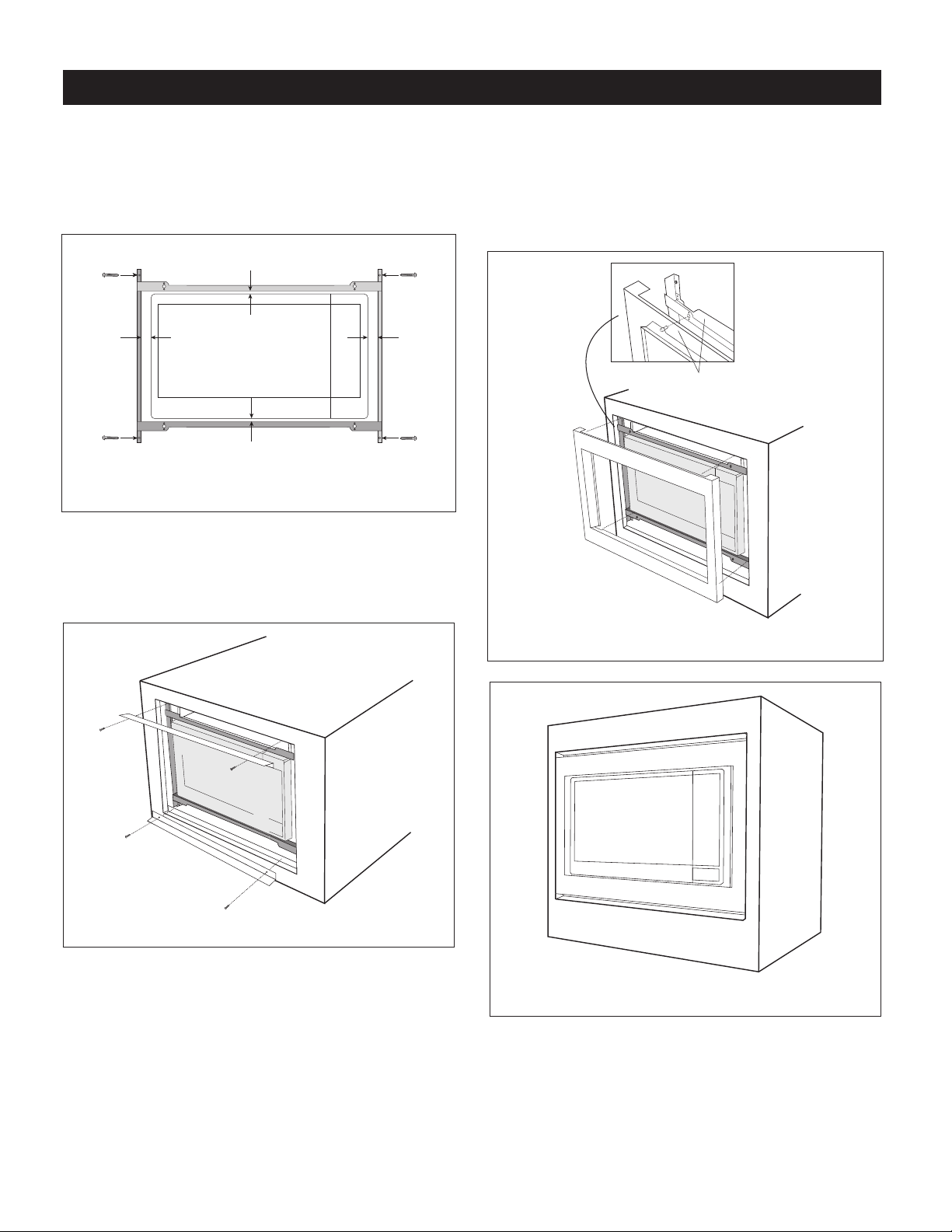
4.BACK FRAME INSTALLATION: Position BACK FRAME
equalspacetoptobottom,sidetoside.Markfor4holes
ontheinstalledwoodcleats,centerpunchandpre-drill
with
1
⁄16"drillbit.Secureframewith4SCREWSE.See
Figure7.
Equal gap top, bottom
Equal gap
side to side
Mounting holes
Mounting holes
Mounting holes
Mounting holes
Screw E
Screw E
Screw E
Screw E
Figure 7
5.InstallAirDeectorstopandbottom.Center(leftandright)
theAir Deectors above and below theinstalled BACK
FRAME. Secure AIR DEFLECTORS with 4 SCREWS E.
See Figure8. Mark holes and pre-drill the wood cleats
with
1
⁄16"drillbit.
Figure 8
6.FRONT FRAME INSTALLATION: Place the FRONT
FRAME onto the BACK FRAME and align ball studs
andreceivers.Securethe FRONTFRAMEto theBACK
FRAME by rmly pushing the FRONT FRAME onto the
BACK FRAME engaging the 4 snap attachments. See
Figures9and10.
Snap
attachment
Figure 9
Figure 10


For any other assistance or information about this kit,
please call Sharp’s Customer Assistance Center at
1-800-BE-SHARP (1-800-237-4277)
SHARP ELECTRONICS CORPORATION
100 Paragon Drive, Montvale, New Jersey 07645
TINSEB618MRR0
Dec 2, 2022