Loading ...
Loading ...
Loading ...
6
7. WIRING INSTALLATION
WARNING
!
Improper grounding can result in a risk of electric shock. Consult a qualified electrician if the grounding instructions
are not completely understood, or if there is any doubt as to whether the appliance is properly grounded. Do not
use an extension cord. If the power supply cord is too short, have a qualified electrician install an outlet near the
appliance, in accordance with all applicable codes and standards. Turn off electrical power at service entrance
before wiring.
GROUNDING INSTRUCTIONS
This appliance must be grounded. In the event of an electrical short circuit, grounding reduces
the risk of electric shock by providing an escape wire for the electric current. This appliance is
equipped with a cord having a grounding wire with a grounding plug. The plug must be plugged
into an outlet that is properly installed and grounded.
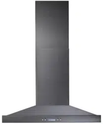
Position the outlet within the space covered by the decorative flue. Place the outlet at a maximum
distance of 24” (from where the cord exits from the hood). The center of the outlet must be
positioned at 3½” from the center of the future hood location (as illustrated beside). Make sure
this does not interfere with a mounting bracket fastening area or with the decorative flue (where
the flue touches the wall).
C
L
C
L
HE0233A
8. INSTALL HOOD MOUNTING BRACKET
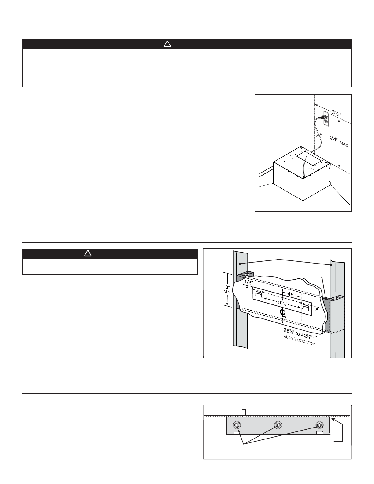
Construct wood wall framing that is even with the surface of wall studs.
Wood wall framing must be at least 1/2” thick and 3” high. Fasten wood wall
framing to wall studs for a solid installation.
Make sure that the height of the framing will allow the mounting bracket
to be secured to the framing within the dimensions shown (see illustration
beside).
After wall surface is finished, carefully center and level the hood
mounting bracket over installation location. Secure it to wall framing using
3 no. 8 x 1½” screws.
Using a level, draw a vertical line up to the ceiling starting from the
mounting bracket center.
9. INSTALL UPPER FLUE MOUNTING BRACKET
WARNING
!
When cutting or drilling into wall, do not damage electrical
wiring and other hidden utilities.
Center the upper flue mounting bracket with the center line previously
drawn in step 8 and place it flush with the ceiling.
Use the upper flue mounting bracket as a template to mark the position of
its screws.
Drill the 3 screw holes using a 3/16” drill bit.
Insert the included drywall anchors into the drilled holes (1 per hole).
Secure the upper flue bracket to the wall using 3 no. 8 x 3/4” screws.
Ensure that the bracket is tight against the wall.
36
7
/8” = BOTTOM OF HOOD 24” ABOVE COOKTOP
42
7
/8” = BOTTOM OF HOOD 30” ABOVE COOKTOP
SCREW LOCATIONS
HD0377
C
L
CEILING
MOUNTING BRACKET
FLUSH WITH CEILING
HD0813A
WALL STUDS
FRAMING BEHIND DRYWALL
Loading ...
Loading ...
Loading ...